- Get custom product tools and services
- Access training
- Manage support cases
- Create and manage your orders (authorized partners only)
Schneider Electric USA Website

Search FAQs
What does the trip class 10, class 20 and class 30 mean for overload relays.
Article available in these languages: Czech , Spanish , Hungarian , Romanian
Released for: Schneider Electric USA
Discuss this topic with experts
Start here!
Find answers now. Search for a solution on your own, or connect with one of our experts.
Contact Support
Reach out to our customer care team to receive more information, technical support, assistance with complaints and more.
Where to buy?
Easily find the nearest Schneider Electric distributor in your location.
Search topic-related frequently asked questions to find answers you need.
Contact Sales
Start your sales inquiry online and an expert will connect with you.

Overload or Thermal Protection (ANSI 49)
Introduction
Overload or thermal protection protects all types of motor applications against overload currents.
Operating Principle
Overload or thermal protection is I 2 t IDMT (Inverse Definite Minimum Time):
o It incorporates the motor thermal image function.
o It can be configured as the Ir pickup and as the trip class (Class).
Tripping curve:
Ir Pickup Setting Value
The overload or thermal protection pickup (Ir) is set by using a multi-position dial.
The default Ir pickup setting value is 0.4 x In (minimum dial value).
The overload or thermal protection tripping range is 1.05–1.20 x Ir according to IEC/EN 60947-4-1 standard.
The following table shows the preset values of the adjustment dial Ir in amperes for each current rating In:
Trip Class Setting Value
The trip class (Class) is set by using an adjustment dial:
o Class 10 (default value)
The trip class corresponds to the value of the tripping time for a current of 7.2 x Ir according to IEC/EN 60947-4-1 standard.
The following table shows the value of the tripping time depending on the current in the load for all three classes:
The precision range is -20%, + 0%
Motor Thermal Image
The model representing heat rise and cooling in a motor load is constructed according to the algorithm for calculating the thermal demand, taking account of the iron and copper losses.
The following figure represents the limit curves for the iron and copper components calculated for class 20:
Thermal Memory
The trip unit uses a thermal memory function to protect the motor from overheating in case of low amplitude repetitive faults.
Electronic protection without thermal memory function does not protect against repetitive faults because the duration of each overload above the pickup setting is too short to cause tripping. However, each overload causes a temperature rise in the installation. The cumulative effect of successive overloads can overheat the system. The thermal memory function remembers and integrates the thermal heating caused by each pickup setting overrun. The thermal memory function remembers the thermal heating values for 20 minutes before or after tripping.
Example: Comparison of the heat rise calculation without thermal image (diagram A ) and with thermal image (diagram B ):
With thermal image, the trip unit adds the thermal effect of successive current pulses. Tripping occurs based on the actual thermal state of the motor.
Cooling Fan
The thermal image of the motor is calculated taking account of the fact that the motor is self-cooled (fan mounted on the shaft end).
DOCA0161EN-01
© 2020 Schneider Electric. All rights reserved.
- Skip to primary navigation
- Skip to main content
- Skip to primary sidebar
- Skip to footer
Motion Control Tips
Automation • Motion Control • Power Transmission
What are thermal overload relays and what motion components do they protect?
✭ By Danielle Collins Leave a Comment
Heat is a major factor in the performance and life of a motor, and one of the primary sources of motor heating is current running through the motor windings. Since heating is an unavoidable condition of motor operation, it’s important to protect the motor from overheating, or thermal overload.
In a previous post, we described several types of sensors that can measure the temperature of motor windings directly. But in some cases — particularly for AC induction motors — motor heating can be measured indirectly by thermal overload relays, which determine motor temperature by monitoring the amount of current being delivered to the motor.
Thermal overload relays are wired in series with the motor, so the current flowing to the motor also flows through the overload relay. When the current reaches or exceeds a predetermined limit for a certain amount of time, the relay activates a mechanism that opens one or more contacts to interrupt current flow to the motor. Thermal overload relays are rated by their trip class, which defines the amount of time for which the overload can occur before the relay responds, or trips. Common trip classes are 5, 10, 20, and 30 seconds.
Taking time, as well as current, into account is important for AC induction motors because they draw significantly more than their full rated current (often 600 percent or more) during startup. So if the relay tripped immediately when the overload current was exceeded, the motor would have difficulty starting.
There are three types of thermal overload relays — bimetallic, eutectic, and electronic.
Bimetallic thermal overload relays (sometimes referred to as heater elements) are made of two metals, with different coefficients of thermal expansion, that are fastened or bonded together. A winding, wrapped around or placed near the bimetallic strip, carries current.
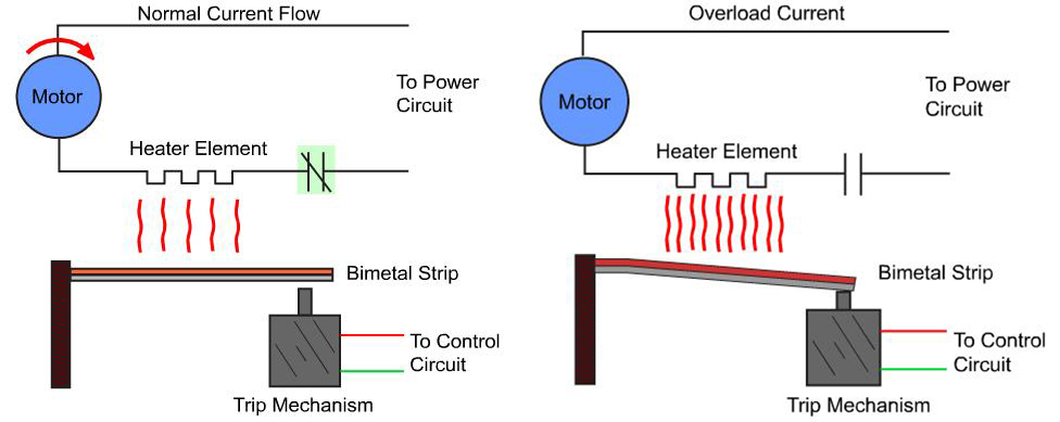
As the current running through the relay (and, therefore, through the motor) heats the bimetallic strip, the two metals expand at different rates, causing the strip to bend toward the side with the lower coefficient of thermal expansion. When the strip bends, it actuates a normally closed (NC) contactor, causing it to open and stopping the current flow to the motor. Once the bimetallic relay has cooled and the metal strips have reverted to their normal state, the circuit is automatically reset and the motor can be restarted.
Eutectic thermal overload relays use a eutectic alloy (a combination of metals that melts and solidifies at a defined temperature), housed in a tube and connected to a heater winding. The supply current to the motor flows through the heater winding and heats the alloy. When the alloy reaches a sufficient temperature, it transforms rapidly to a liquid.
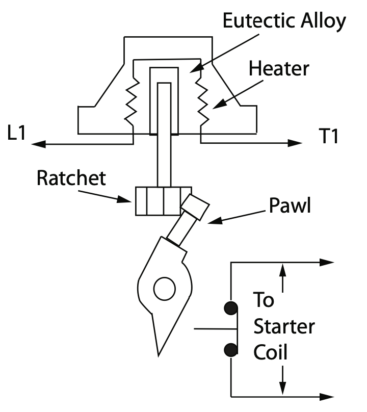
As a solid, the alloy holds a mechanical device, such as a spring or ratchet, in place. But when the alloy melts, the mechanical device releases, opening the overload contacts. Like the bimetallic design, a eutectic thermal overload relay cannot be reset until the alloy has sufficiently cooled and returned to its original, solid state.
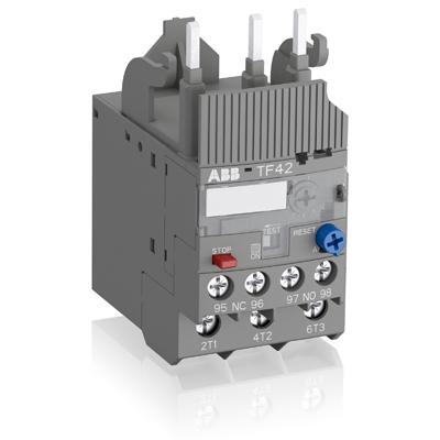
Electronic thermal overload relays measure current electronically, rather than relying on a heater mechanism, and so are insensitive to changes in ambient temperature. They’re also less prone to “nuisance,” or false, tripping. Electronic overload relays can provide data such as the percentage of thermal capacity utilization (%TCU), percentage of full-load amps (%FLA), time-to trip, current RMS, and ground fault current — information that can help operators conduct diagnostics and predict when the relay is at risk of tripping.
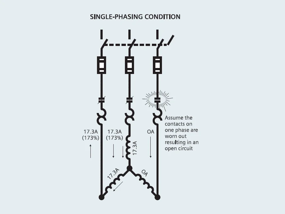
Electronic designs can also protect motors against phase loss (also referred to as phase failure), which occurs when one phase of current equals zero amps, often due to a short circuit or blown fuse. This causes the motor to draw excessive current on the remaining two phases and leads to significant motor heating.
Thermal overload relays are typically part of the motor starter , which includes the overload relay plus contacts. It’s important to note that thermal overload relays are only designed to protect the motor from overheating, and won’t trip if there’s a short circuit, so additional fuses or circuit breakers are necessary to protect the circuit.
You may also like:
Reader Interactions
Leave a reply.
You must be logged in to post a comment.

DESIGN WORLD NETWORK
Motion control tips.

ELECTRICAL CLASSROOM
A complete Electrical Engineering portal
Overload relay – Principle of operation, types, connection
Every motor must be protected from all possible faults to ensure prolonged and safe operation as well as time loss caused due to breakdown. Almost all industries rely on the electric motor to control their processes and production. Hence it is necessary to make the motor fail-safe.
The most vulnerable part of a motor is its winding insulation. The winding insulations are at high risk of damage by excessively high temperatures. Overload relay is one such device that protects a motor from damage caused due to overloads and over-currents. It is used with contactors and can be found in motor control centers and motor starters.
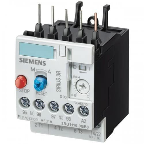
Principle of operation
Types of overload relays, working of bimetallic thermal overload relay, working of electronic overload relay, parts of a thermal overload relay, symbol of an overload relay, frequently asked questions, definition of overload relay.
An overload relay is a device that protects an electric motor against overloads and phase failure.
It senses the overloading of the motor and interrupts the power flow to the motor, thus protecting it from overheating and winding damages. Apart from overloads, it can also protect the motor from phase loss/ failures and phase imbalance . They are very commonly known as OLR .
What is an overload?
An overload is a condition at which a motor draws a current above its rated value, for a prolonged period. (adsbygoogle = window.adsbygoogle || []).push({});
It is the most encountered fault and can result in temperature rise in the motor winding. Hence the rapid return to normal operation is important.
A thermal overload relay works in the principle of electro-thermal properties in a bimetallic strip. It is placed in the motor circuit in such a way that the current to the motor flows through its poles. The bimetallic strip gets heated up by the current directly or indirectly and when the current flow exceeds the set value, it bends.
They always work in combination with contactors. When the bimetallic strips heat up, the trip contact is activated that in turn breaks the power supply to the contactor coil, de-energizing it and breaking the current flow to the motor. This tripping time is always inversely proportional to the current flow through the OLR. Hence higher the current flow faster shall it trips. Therefore, thermal overload relays are referred to as current-dependent and inversely time-delayed relays.
Overload relays can be classified as follows:
- Bimetallic thermal overload relays
- Electronic overload relays
The working principle of the above differs a little from each other. Let us discuss it in the following sections.
As explained above, a bimetallic thermal relay works on the heating property of the bimetallic strip. In the direct heating method, the full current to the motor flows through the OLR. Therefore, it gets heated up directly by the current.
But in the case of indirect heating, the bimetallic strip is held in close contact with the current-carrying conductor inside the OLR. Excessive current flow to the motor heats up the conductor and hence the bimetallic strip. The conductor shall be insulated hence no current flow through the strip.
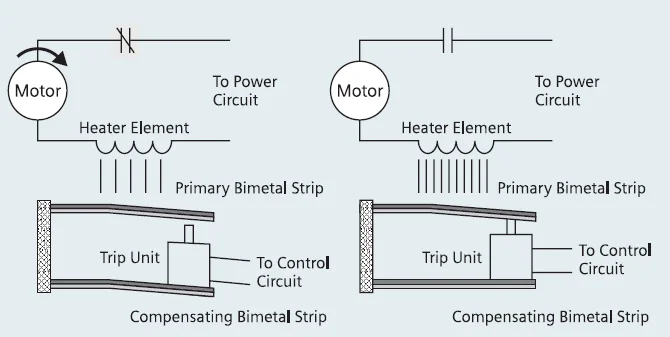
Electronic overload relays do not have a bimetallic strip inside. Instead, it uses temperature sensors or current transformers to sense the amount of current flowing to the motor. It uses microprocessor-based technology for protection. Temperature is sensed using PTC and the same is used to trip the circuit in case of overload faults. Some electronic overload relays come with current transformers and Hall effect sensors that directly sense the amount of current flow.
The major advantage of electronic OLR over thermal OLR is that lack of bimetallic strip results in low heat losses inside the relay. Also, Electronic relays are more precise than thermal relays. Some manufacturers build electronic relays with extensive features such as earth fault protection, motor stall protection, etc. Electronic overload relays are much suited for applications that require a frequent start and stop of motors.
In addition, manufacturers offer built-in RTD or thermocouples that can be directly used to measure the winding temperature. These measurements can be used for more accurate thermal overload protection.
They are designed in such a way to withstand the starting current (which is typically 6 to 10 times the full load current) of the motor for a limited period (typically 15-30 seconds depending on the threshold of current).
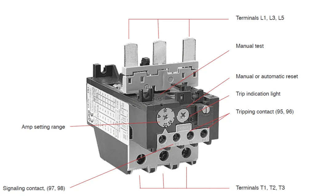
Apart from the bimetallic strip and contacts discussed in the working principle section above, there are a few more parts in an overload relay that needs to be understood.
Terminals L1, L2, and L3 are input terminals. It can be directly mounted to the contactor. Supply to the motor can be connected to Terminals T1, T2, and T3.
Ampere range setting
A rotary knob is present over the overload relay. Using this knob, the rated current of the motor can be set. The current can be set between the upper and lower limits provided. In the case of an electronic overload relay, an additional knob for tripping class selection is also provided.
Reset Button
A reset button is present over the overload relay to reset the overload relay after a trip and clearance of fault.
Manual/Auto reset selection
With the manual/auto reset selection button, we can choose between manual and automatic reset of these relays after a trip. If the device is set to auto, a remote reset of OLR is possible.
Auxiliary contact
They are provided with two auxiliary contacts – one NO (97-98) and another NC (95-96). NO contact is for trip signaling and NC contact is for disconnecting the contactor. NC contacts should be capable of direct switching of contactor coil.
Test button
Using the test button, it is possible to test the control wiring.
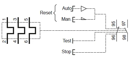
Here 1, 2, 3, 4, 5 and 6 are power terminal 95 & 96 are trip contacts and 97 & 98 are signaling contacts. Learn how to use them in a circuit here: Star-Delta starter wiring diagram – Control and power wiring diagrams
What is the trip Class of overload relay?
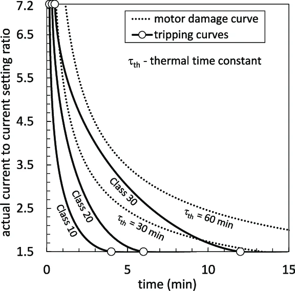
The time taken by them to open the contactor during overloads is specified by the trip class . It is commonly classified into Class 10, Class 20, Class 30, and Class 5. The OLR trips in 10 seconds, 20 seconds, 30 seconds, and 5 seconds respectively at 600% of full load current to the motor.
Class 10 and Class 20 are very commonly used ones. Class 30 overload relays are used for the protection of motors driving high inertia loads and Class 5 relays are used for the motors requiring very fast tripping.
How to use an overload relay in a circuit?
They are always used in combination with the contactors in the circuit. It is connected in line with the motor such that the current to the motor fully flow through it. Below are the various types of connections for single-phase and three-phase motors.
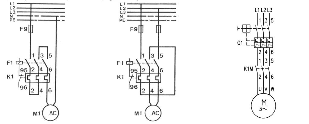
Read more: Sizing of contactor and overload relay for 3 Phase DOL starter Read more on star delta starters: Star-delta starter (Wye-Delta Starters) – Circuit, working . Read more about contactors: Contactor – Construction, Operation, Application and Selection
What causes the OLR trip?
As discussed above, there are three major conditions for overload trips :
- Overloading of the motor.
- Input phase loss
- Phase imbalance.
Apart from these, there may be some additional protection features available. This varies from one manufacturer to the other.
How does an overload relay protect from phase failures?
During normal operation, the current flowing through each pole of an overload relay to the motor remains the same at a time. If anyone of the phase is interrupted, the current through the other two phases rises to 1.73 times the normal value. Hence the overload relay gets heated up and it trips. Phase failure is also known as single phasing of motor or phase loss.
Can OLR protect from short circuits?
Overload relays cannot protect against short circuits. They should always be used with short circuit protection devices. Otherwise, any short circuits in the motor can potentially damage them. They can protect against overloads, phase loss, and phase imbalance, but not short circuits.
What could damage an overload relay?
The device will be damaged if the backup short circuit protection device (circuit breaker or fuse) is overrated. This may also damage the whole starter and even the motor windings themselves. Therefore it is advised to stick on to the maximum short circuit protection advised by the relay manufacturer.
An overload relay is a device that can protect a motor from overloads, phase failure, and phase imbalances. Based on the principle of operation they are classified into thermal and electronic overload relays. Thermal OLR is based on the principle of deformation of a bimetallic strip on heating. The electronic overload relay is a microprocessor-based device and comes with extensive built-in functionalities.
OLRs are used in combination with the contactors. It opens the contactor whenever it senses a fault. The time taken by them in opening the contactor during overloads is specified by their trip class. Overload relays cannot protect against short circuits. This sample datasheet can help you understand the relay ratings. They could be easily damaged if underrated or under with an overrated short circuit protection device (Fuse or Circuit breaker).
Related articles
Relay – Operation, types and applications
Difference between NO and NC
Difference between electromechanical relays and solid-state relays
Difference between earth leakage relay and earth fault relay
Buchholz Relay – Working Principle, Construction and Operation
Difference between contactors and relays
2 thoughts on “Overload relay – Principle of operation, types, connection”
Excellently described. Brief, to the point and comprehensive text.
Leave a Comment Cancel reply

Hazardous area
Thermal overload relays, motor protection for overload and phase failure.
Thermal overload relays are economic electromechanical protection devices for the main circuit. They offer reliable protection for motors in the event of overload or phase failure. The thermal overload relay can make up a compact starting solution together with contactors.
- Reliable in harsh environments such as oil and gas, chemical industries
- Reliable protection for motors
- Easy to create starters
- Optimized match to ABB contactors
- Single mounting kits and wire reset for remote control available for specific applications.
- Approved for use in hazardous environments
- Trip class 10
- Adjustable current setting ranges
- Overload protection with phase loss sensitivity
- Temperature compensation up to +60°C
- Automatic or manual reset, sealable.

Hazardous area approvals:
- ATEX, IEC-Ex.

Tools and Support

Product data

Related products
Submit your inquiry and we will contact you
- Middle East and Africa
- Asia and Oceania
- Austria - German
- Belgium - Dutch | French
- Bulgaria - Bulgarian
- Croatia - Croatian
- Czech Republic - Czech
- Denmark - Danish
- Estonia - Estonian
- Finland - Finnish
- France - French
- Germany - German
- Greece - Greek
- Hungary - Hungarian
- Ireland - English
- Italy - Italian
- Latvia - Latvian
- Lithuania - Lithuanian
- Luxembourg - French
- Netherlands - Dutch
- Norway - Norwegian
- Poland - Polish
- Portugal - Portuguese
- Romania - Romanian
- Russia - Russian
- Serbia - Serbian
- Slovakia - Slovakian
- Slovenia - Slovenian
- Spain - Spanish
- Sweden - Swedish
- Switzerland - French | German | Italian
- Turkiye - Turkish
- United Kingdom - English
- Argentina - Spanish
- Aruba - Spanish
- Bolivia - Spanish
- Brazil - Portuguese
- Canada - English | French
- Chile - Spanish
- Colombia - Spanish
- Costa Rica - Spanish
- Dominican Republic - Spanish
- Ecuador - Spanish
- El Salvador - Spanish
- Guatemala - Spanish
- Honduras - Spanish
- Mexico - Spanish
- Panama - Spanish
- Peru - Spanish
- Puerto Rico - Spanish
- United States of America - English
- Uruguay - Spanish
- Algeria - English | French
- Angola - English | French
- Bahrain - English | French
- Botswana - English | French
- Cameroon - English | French
- Côte d'Ivoire - English | French
- Egypt - English | French
- Ghana - English | French
- Israel - Hebrew
- Jordan - English
- Kenya - English | French
- Kuwait - English
- Lebanon - English
- Madagascar - English | French
- Mali - English | French
- Mauritius - English | French
- Morocco - English | French
- Namibia - English | French
- Nigeria - English | French
- Oman - English
- Pakistan - English
- Palestine - English
- Qatar - English
- Saudi Arabia - English
- Senegal - English | French
- South Africa - English
- Tanzania - English | French
- Tunisia - English | French
- Uganda - English | French
- United Arab Emirates - English
- Zambia - English | French
- Zimbabwe - English | French
- Australia - English
- Bangladesh - English
- China - Chinese | English
- India - English
- Indonesia - English
- Japan - Japanese
- Kazakhstan - Russian
- Malaysia - English
- Mongolia - Mongolian | English
- New Zealand - English
- Philippines - English
- Singapore - English
- South Korea - Korean
- Sri Lanka - English
- Taiwan (Chinese Taipei) - Chinese - Traditional
- Thailand - English
- Vietnam - English
abb.com privacy settings
Our website uses cookies which are necessary for running the website and for providing the services you request. We would also like to set the following optional cookies on your device. You can change these settings any time later by clicking "Change cookie settings" at the bottom of any page. For more information, please read our privacy notice.
We collect statistics to understand how many visitors we have, how our visitors interact with the site and how we can improve it. The collected data does not directly identify anyone.
We store choices you have made so that they are remembered across visits in order to provide you a more personalized experience.
Your browsing behavior is tracked across websites by advertising and social network service providers. You may see tailored advertising and content on other websites based on your browsing profile.
Preferences
Advertising and tracking
Popular links
- ABB Connect
- ABB Electrification
- Where to buy
- Mission to Zero
- ABB Ability
- Supplying to ABB
- Customer events
- Investor events
- Media events
Thermal Overload Relay
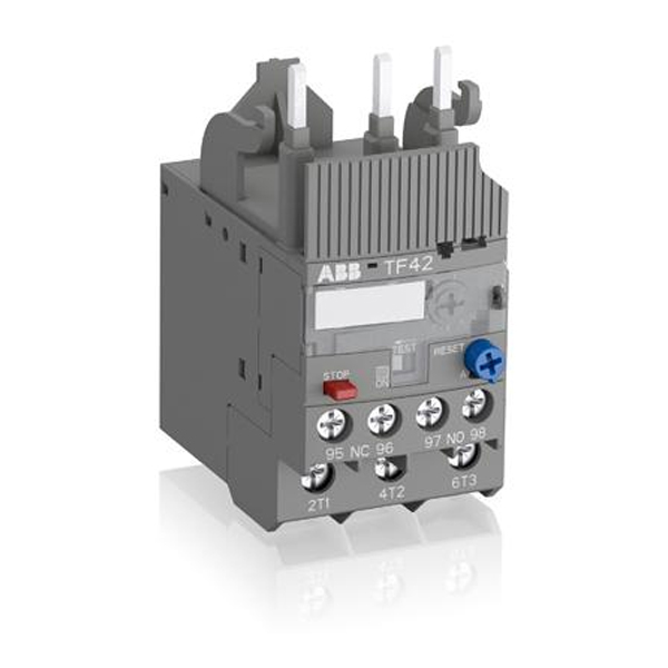
Motor protection for overload and phase failure Thermal overload relays are economic electromechanical protection devices for the main circuit. They offer reliable protection for motors in the event of overload or phase failure. The thermal overload relay can make up a compact starting solution together with contactors.
Features and benefits
- Reliable protection for motors
- Easy to create starters
- Optimized match to ABB contactors
- Single mounting kits and wire reset for remote control available for specific applications.
- Trip class 10
- Adjustable current setting ranges
- Overload protection with phase loss sensitivity
- Temperature compensation up to +60°C
- Automatic or manual reset, sealable
- Stop and test function.
Publications
- Application and Technical
- Catalogs and Buyers Guides
- Environmental Product Declaration
- Installation and Instruction
- Renewal Parts
Other Overload Relays IEC
Overload Relay – Definition, Types, and Principle
Overload relay is very common when we are dealing with electric motors. Why is that?
Electric motors are often used in equipment that include rotating parts. Because motors are often fairly costly, it’s critical to avoid them failing due to carrying more electric current than their rated amperage.
Ground faults (short-circuits in the motor windings or peripheral cables) can cause electrical overload, but jamming or inappropriate operation are more prevalent causes.
Every motor must be protected against all possible flaws in order to ensure long-term, safe operation and save time lost due to breakdown. Almost all industries rely on electric motors to regulate their processes and output. As a result, the engine must be made fail-safe.
Overload relays are one type of device that prevents a motor from being damaged by overloads and overcurrents. It’s found in motor control centers and motor starters, and it’s used with contactors .
What is Overload Protection?
Overload relay is one types of relays we will encounter one day.
Overload relay is mostly used as an overload protection. But what is overload protection?
An overload occurs when the motor consumes too much current. This may cause the motor to overheat, causing damage to the windings. As a result, it’s critical to protect the motor, motor branch circuit, and motor branch circuit components from overload.
Overload relays protect the motor, motor branch circuit, and motor branch circuit components from excessive heat caused by an overload. The motor starter includes overload relays (assembly of contactor plus overload relay).
They protect the motor by keeping an eye on the current going through the circuit.
If the current exceeds a preset limit for an extended length of time, the overload relay trips, activating an auxiliary contact that terminates the motor control circuit and de-energizes the contactor.
As a result, the motor’s power is turned off. The motor and motor circuit components do not overheat and become damaged when there is no power.
Overload relays can be manually reset, and some overload relays will reset themselves after a period of time. After that, the motor can be turned back on.
Overload Relay Definition
Overload relays are devices that protect electric motors from overloads and phase failure.
When the motor is overloaded, it detects this and terminates the power flow, preventing the motor from overheating and winding damage.
It can also protect the motor from phase loss/failures and phase imbalance, in addition to overloads. They’re usually referred to as OLR.
What is an overload, exactly?
An overload occurs when a motor draws a current that is greater than its rated value for an extended length of time.
It’s the most common problem, and it might cause the motor winding to overheat. As a result, a quick return to regular operation is critical.
Read also : basic direct current circuit
Overload Relay Parts
Aside from the bimetallic strip and contacts indicated in the working principle section, there are a few other components in an overload relay worth mentioning.
Observe the thermal overload relay below:
Input terminals L1, L2, and L3 are available. It can be mounted directly to the contactor. Terminals T1, T2, and T3 can be used to supply power to the motor.
Ampere range toggle
Over the overload relay, there is a rotary knob. The rated current of the motor can be set with this knob. The current can be adjusted between the supplied upper and lower limits. In the case of an electronic overload relay, there is also a knob for selecting the tripping class.
Reset button
The overload relay has a reset button that can be used to reset it after a trip and fault clearance.
Automatic-Manual reset mode
We can choose between manual and automatic reset of these relays after a journey using the manual/auto reset selection button. A remote reset of OLR is available if the device is set to auto.
Auxiliary contact
They come with two auxiliary contacts: one NO (97-98) and one NC (97-98). (95-96). The NO contact is used to signify a trip, whereas the NC contact is used to disconnect the contactor. NC contacts should be able to switch the contactor coil directly.
Testing button
The control wiring can be tested by pressing the test button.
Overload Relay Symbol
One thing you should know and understand is that every electrical component, element, and device have their symbol.
This symbol will make it easier to use when drawing, designing, and analyzing.
Observe the symbol of thermal overload relay below:
Terminals 1, 2, 3, 4, 5 and 6 are power terminals Terminals 95 and 96 are trip contacts Terminals 97 and 98 are signal contacts.
Overload Relay Connection Diagram
The overload relay connection diagram is given below, and the overload relay sign is represented by two opposite question marks.
Otherwise, the overload relay function is addressed using the ‘S’ symbol. Although there are many different types of overload relays on the market, the “bimetallic thermal overload relay” is the most commonly utilized.
This relay’s design incorporates two different types of metal strips, which can be interconnected and grow at various speeds when heated.
When this strip reaches a specific temperature, it can provide enough turns to break the circuit.
After a few seconds, the overload is identified when the flow to the motor exceeds the charge for the heater. The time of the relay exploration is used to classify overload relays into three sorts.
Overload relays for 10 seconds, 20 seconds, and 30 seconds can be found in the Class 10, Class 20, and Class 30 categories.
This relay’s key characteristic is that it prevents the engine from starting right away. The overload relay, for example, probes into the bimetallic relay, and the NC (normally closed) bimetallic connections release the circuit until the strip cools.
The motor will not start if any contactor tries to push the start switch to turn it off.
Principle of Overload Relay
The electro-thermal characteristics of a bimetallic strip are used to operate a thermal overload relay. It is wired into the motor circuit so that the current flows through the poles of the motor.
The current heats the bimetallic strip directly or indirectly, and it bends when the current flow surpasses the predetermined value.
They’re always used in tandem with contactors. When the bimetallic strips heat up, the trip contact opens, cutting off power to the contactor coil, de-energizing it and interrupting current flow to the motor.
The current flow through the OLR is always inversely proportional to the tripping time. As a result, the stronger the current flow, the faster it will trip.
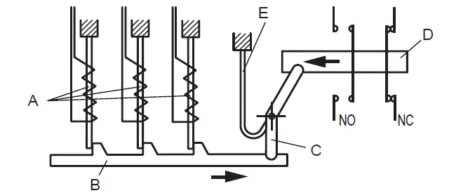
A = Indirectly heated bimetal strips B = Trip slide C = Trip lever D = Contact lever E = Compensation bimetal strip
Thermal overload relays are thus described as current-dependent and inversely time-delayed relays.
Overload Relay Types
The following are the several types of overload relays:
- Bimetallic thermal overload relays
- Electronic overload relays
- Eutectic overload relays
- Solid state overload relays
Each of the above works on a somewhat different principle. Let’s have a look at it in the parts below.
Bimetallic Thermal Overload Relay: How it Works
A bimetallic thermal relay, as previously stated, relies on the heating properties of a bimetallic strip. The complete current to the motor flows through the OLR in the direct heating approach.
As a result, the current heats it up directly.
Indirect heating, on the other hand, keeps the bimetallic strip in close contact with the current-carrying wire inside the OLR. The conductor and, as a result, the bimetallic strip heats up when there is too much current flowing to the motor.
Because the conductor is insulated, no current can pass through the strip.
Electronic Overload Relay: How it Works
This is also known as solid state overload relays.
There is no bimetallic strip inside electronic overload relays. Instead, it detects the amount of current flowing to the motor using temperature sensors or current transformers. It protects you using microprocessor-based technologies.
PTC is used to sense temperature and to trip the circuit in the event of an overload fault. Current transformers and Hall effect sensors are included in some electronic overload relays, which directly sense the amount of current flowing.
The lack of a bimetallic strip in electronic OLR leads to low heat losses inside the relay, which is a major advantage over thermal OLR.
Electronic relays are also more accurate than thermal relays.
Electronic relays from some manufacturers come with a variety of characteristics, such as earth fault protection, motor stall protection, and so on.
Earth fault protection can also be achieved using CBCT on the secondary three phase windings.
Electronic overload relays are ideal for applications where motors must start and stop frequently.
They are built to sustain the motor starting current (which is normally 6 to 10 times the full load current) for a limited time (typically 15-30 seconds depending on the threshold of current).
Eutectic Overload Relay: How it Works
A heater winding, a mechanical mechanism for activating a tripping mechanism, and a eutectic alloy make up this sort of overload relay. An eutectic alloy is made up of two or more components that solidify or melt at a given temperature.
The eutectic alloy is housed in a tube in the overload relay, which is frequently used in conjunction with a spring-loaded ratchet wheel to trigger the tripping mechanism during overload operations.
The little heater winding conducts the motor current. The heater winding heats the eutectic alloy tube during the overload.
As a result of the heat, the alloy melts, releasing the ratchet wheel and allowing it to turn. The overload relay’s closed auxiliary contacts are opened as a result of this action.
After tripping, Eutectic overload relays can only be manually reset. This is commonly accomplished by pressing a reset button located on the relay’s cover.
The heating unit put on the relay is selected based on the motor’s full load current.
Overload Relay Trip Class
The trip class specifies how long it takes them to open the contactor during overloads.
Observe the table below from Schneider:
Class 10, Class 20, Class 30, and Class 5 are the most popular classifications. At 600 percent of full load current to the motor, the OLR trips in 10 seconds, 20 seconds, 30 seconds, and 5 seconds, respectively.
Class 10 and Class 20 are the most widely utilized. Motors generating high inertia loads are protected by Class 30 overload relays, while motors requiring very fast tripping are protected by Class 5 relays.
They are always utilized in conjunction with the circuit’s contactors. It is wired in series with the motor, allowing the electricity to flow freely through it.
The many methods of connectors for single-phase and three-phase motors are listed below.
Overload relays K1 and K1M are used. A single phase motor connection is shown in the first and second pictures, while a three phase motor connection is shown in the third.
Overload Relay Advantages
Overload protection relays come in a variety of shapes and sizes. Fuse, thermal relays, electromechanical relays, and electronic relays are examples.
Low-current devices, such as domestic appliances, are frequently protected by fuses.
High-current machinery, such as industrial motors, are protected by thermal, electromechanical, and electronic relays.
The following are the key advantages of relays:
1. PROTECTION THAT CAN BE RELIED ON When a high-current scenario arises owing to a ground fault, short circuit, phase failure, or mechanical jamming, overload relays turn off electricity to the motor. They’re a low-cost technique to reduce downtime while repairing or replacing motors that have failed due to excessive current.
2. MATCHING CONTRACTORS APPROPRIATELY Contractors carry the main circuit’s high operational currents. They contain built-in systems to prevent arcing caused by heavy motor current interruption. When contactors and thermal relays are appropriately matched, the result is a good motor starting circuits
3. STARTERS ARE SIMPLE TO USE. Manual motor starters are used to turn on and off motors. These electromechanical devices are simple to set up and reset once they have tripped.
4. MOUNTING KITS For several types of overload protection relays, application-specific mounting kits are provided.
To control their activation threshold, overload protection relays have adjustable current setting ranges. They can detect and defend against phase faults in addition to preventing electrical overload.
Because these relays are frequently used in hot situations, they have ambient temperature tolerances of up to 60 degrees Celsius.
Relays also include sealable automatic or manual resets to protect them from the hazardous conditions in which they work.
While not carrying an electrical current, relays have stop and test operations to ensure their operational integrity.
Overload Relay vs Circuit Breaker
What is the difference between an overload and a current that is too high?
A type of overcurrent is an overload. Overload is an overcurrent that is sustained within the boundaries of the equipment’s permitted current rating yet causes the equipment to overheat.
Overcurrent is usually instantaneous. A type of overcurrent is a short circuit.
What is an overload in a circuit, for example?
When you draw more electricity than a circuit can safely handle, you have an overload. Wiring, a breaker (or a fuse in older wiring systems), and gadgets make up a circuit (such as light fixtures, appliances, and anything plugged into an outlet).
Is overload protection provided by a circuit breaker in this case?
A circuit breaker is an electrical switch that operates automatically to safeguard an electrical circuit from harm caused by an overload or short circuit.
Its primary purpose is to stop current flow when a defect is identified.
What is an overload protection device, and how does it work?
When the current reaches a level that causes an excessive or dangerous temperature rise in conductors, an overcurrent protection device opens to protect the circuit.
Short-circuit or ground-fault current values, as well as overload circumstances, are detected by most overcurrent protection devices.
1. Why is the OLR tripped?
As previously stated, there are three key factors that lead to overload trips:
- The motor is overloaded.
- Loss of input phase
- Unbalanced phase.
Aside from this, various more security features may be available. This varies depending on the manufacturer.
2. How does overload relay protect from phase failures?
The current flowing through each pole of an overload relay to the motor remains constant during normal operation.
If one of the phases is disrupted, the current in the other two phases increases to 1.73 times its typical value.
As a result, the overload relay heats up and trips. Single phasing of the motor or phase loss are other terms for phase failure.
3. Is an overload relay able to protect from short circuits?
Short circuits are not protected by overload relays. Short circuit protection devices should always be utilized with them.
Otherwise, any short circuits in the motor could cause them to fail. Overloads, phase loss, and phase imbalance are all protected, but short circuits are not.
2 thoughts on “Overload Relay – Definition, Types, and Principle”
Thanks, these notes are very helpful for the people how learn electrical installation course or electrical engineering.
The information I have received is very helpful,you are doing an amazing job I can’t compare to any other,thank you very much.
Leave a Comment Cancel reply
Save my name, email, and website in this browser for the next time I comment.
Sorry, we're unable to complete your request
We cannot complete your request due to a technical difficulty. You may return to the previous page or go to the homepage and explore other options. For immediate assistance please call us.
Error Ref: %26%2332%3b%26%2335%3b18%26%2346%3b536a645f%26%2346%3b1714996664%26%2346%3b946d6a6
- Introduction
- Motor Failure and Protection
- Protection of Motor Branch-Circuits
- Withstand Ratings
- Melting Alloy Overload Relays
- Automatic Reset
- Ambient-Temperature Compensated Bimetallic Overload Relays
- Thermal Overload Relay Trip Characteristics
- Phase Loss and Phase Unbalance
- Separate Mounting—Melting Alloy Overload Relays
- Replacement Melting Alloy Overload Relays for Class 8536 Starters
- Special Features for Melting Alloy Overload Relays
- NEMA Style Melting Alloy Overload Relays Dimensions
- Class 9998 Contact Units
- Class 9999 Isolated Alarm Contacts
- Class 9998 Jumper Strap Kits
- Other Features
- Class 9065 Motor Logic SSOLR Selection Tables
- NEMA Style Dimensional Diagrams
- Isolated Auxiliary Contacts
- DIN Adapter
- Lug-Lug and Lug-Extender Kits
- Remote Reset Module
- Adapted Bimetallic or SSOLR Mounting Bracket Adapter—NEMA Sizes 00–1
- TeSys™ D Solid-State Overload Relays for Type S Starters
- Communication Protocols
- Protection Functions
- Meter Functions
- Motor Control Functions
- Motor Control Modes
- Statistical and Diagnostic Functions
- Standards and Certifications
- Configuration
- LTMR Controllers
- Expansion Module
- HMI Modules
- Transformers, Senors, and Probes
- SoMove™ Software for Configuration
- Accessories for Connecting the Components
- Dimensional Diagrams (mm)
- External Reset Mechanisms — Class 9066
- Nameplate vs. NEC Full-Load Current
- Service Factor
- Motor Branch-Circuit Design
- Thermal Overload Relays
- Motor Logic Solid-State Overload Relays
- Application
- Procedure for Thermal Unit Selection
- Selecting Slow Trip Thermal Units
- Selecting Thermal Units
Procedure for Calculating the Trip Current Rating
- Calculating the Trip Current for Ambient Temperatures Other than 40 °C
- Thermal Unit Selection on an Approximate Basis—Based on Horsepower and Voltage
- Mounting the Thermal Units
For the best experience of this site, please enable Javascript for the www.productinfo.schneider-electric.com domain.
Use the selection table for the specific controller involved.
Find the minimum motor full-load current listed for the thermal unit.
Multiply that current by 1.25 (1.15 for Class 8198). The result is the trip current rating.
Determine the thermal unit selection and trip current rating for thermal units in a Class 8536 Type SCG3 Size 1 magnetic starter used to control a three-phase, 1.15 service factor motor with a full-load current of 17.0 Amperes, where the motor and controller are both located in a 40 o C (104 o F) ambient temperature.
From thermal unit Table 13 , the proper selection is B32.
The minimum motor full-load current is 16. 0 Amperes.
Trip current rating is 16.0 x 1.25= 20.0 Amperes.
Protection Level: Is the relationship between trip current rating and full-load current. Protection level, in percent, is the trip current rating divided by the motor full-load current times 100. In the example above, the protection level for the B32 thermal unit is: 20.0/17.0 x 100=118%.
National Electrical Code, Section 430-32, allows a maximum protection level of 125% for the motor in the above example.
Minimum Trip Current: Also called ultimate current, may vary from the trip current rating value, since ratings are established under standardized test conditions. Factors which influence variations include:
The number of thermal units installed
Enclosure size
Proximity to heat producing devices
Size of conductors installed
Ambient (room) temperature, and others
Except for ambient temperature-compensated overload relays, an ambient temperature higher than 40 o C would lower the trip current, and a lower temperature would increase it. This variation is not a factor in selecting thermal units for the average application, since most motor ratings are based on an ambient temperature of 40 °C, and motor capacity varies with temperature in about the same proportion as the change in trip current. Temperature-compensated relays maintain a nearly constant trip current over a wide range of ambient temperature, and are intended for use where the relay, because of its location, cannot sense changes in the motor ambient temperature.
Show QR code for this page
Was this helpful?
Contact Information
Legal information.
The information provided in this document contains general descriptions, technical characteristics and/or recommendations related to products/solutions.
This document is not intended as a substitute for a detailed study or operational and site-specific development or schematic plan. It is not to be used for determining suitability or reliability of the products/solutions for specific user applications. It is the duty of any such user to perform or have any professional expert of its choice (integrator, specifier or the like) perform the appropriate and comprehensive risk analysis, evaluation and testing of the products/solutions with respect to the relevant specific application or use thereof.
The Schneider Electric brand and any trademarks of Schneider Electric SE and its subsidiaries referred to in this document are the property of Schneider Electric SE or its subsidiaries. All other brands may be trademarks of their respective owner.
This document and its content are protected under applicable copyright laws and provided for informative use only. No part of this document may be reproduced or transmitted in any form or by any means (electronic, mechanical, photocopying, recording, or otherwise), for any purpose, without the prior written permission of Schneider Electric.
Schneider Electric does not grant any right or license for commercial use of the document or its content, except for a non-exclusive and personal license to consult it on an "as is" basis.
Schneider Electric reserves the right to make changes or updates with respect to or in the content of this document or the format thereof, at any time without notice.
To the extent permitted by applicable law, no responsibility or liability is assumed by Schneider Electric and its subsidiaries for any errors or omissions in the informational content of this document, as well as any non-intended use or misuse of the content thereof.
© 2019 – 2021 Schneider Electric.

IMAGES
VIDEO
COMMENTS
Trip classes according to NEMA. NEMA Standard MG-1 defines 4 types of Classes. The most common classes are 5, 10, 20 & 30. Class 5, 10, 20 & 30 overload relays will trip within 5, 10, 20 & 30 seconds respectively at 600% of motor full load amps. A Class 10 overload relay, for example, has to trip the motor offline in 10 seconds or less at 600% ...
Issue: Meaning of Trip Classes for overload relays. Product Line: NEMA Overload Relays Environment: North American Products Resolution: The trip class means that at 600% (6 times) of the maximum thermal current rating (or 600% of the actual dial setting on adjustable overloads) the Class 10 will trip in 10 seconds or less, Class 20 will trip in 20 seconds or less, and Class 30 will trip in 30 ...
Trip Class Designation Regardless of the product style (NEMA or IEC), overload relays respond to overload relay conditions according to trip curves. These trip curves are defined by the class of protection required (see Table 1). ... Thermal Overload Relay Trip Characteristics Melting alloy and bimetallic overload relays are designed to ...
Thermal Overload Relay Trip Characteristics. Melting alloy and bimetallic overload relays are designed to approximate the heat actually generated in the motor. As the motor temperature increases, so does the temperature of the thermal unit. The motor and relay heating curves (in the figure Overload Relay Trip Curve) show this relationship.
The overload or thermal protection pickup (Ir) is set by using a multi-position dial. The default Ir pickup setting value is 0.4 x In (minimum dial value). The overload or thermal protection tripping range is 1.05-1.20 x Ir according to IEC/EN 60947-4-1 standard. The following table shows the preset values of the adjustment dial Ir in amperes ...
Standard technical data, operating data and dimensions see TA...Relay Main Catalog Thermal Overload Relays with Trip Class 20 Resistances and power losses per phase Short-circuit protection Thermal overload relay TA25DU trip class 20 1.3 … 1.8 10 25 6 - 670.3 2.2 1.7 … 2.4 16 25 10 - 381 2.2 2.2 … 3.1 16 25 10 - 235.3 2.3
The thermal overload relays are three pole relays with bimetal tripping elements (1 per pole). The motor current flows through the bimetal tripping elements and heats them directly and indirectly. In case of an overload (over current), the bimetal ... Trip class 10 Rated frequency 50/60 Hz Number of poles 3 Resistance per pole see table on page 3
This is the principle behind the ' thermal replica ' model of a motor used for overload protection. The temperature T at any instant is given by: where: Tmax = final steady state temperature. τ = heating time constant. Temperature rise is proportional to the current squared: where: IR = current which, if flowing continuously, produces ...
Thermal overload relays measure motor heating indirectly by monitoring the amount of current being delivered to the motor. ... Thermal overload relays are rated by their trip class, which defines the amount of time for which the overload can occur before the relay responds, or trips. Common trip classes are 5, 10, 20, and 30 seconds.
In order for the thermal overload relay to trip, the relay's full load current point must be set to match the value on the rating plate. Temperature trip range applies to relays which are designed to measure temperature instead of current, such as solid state or temperature control relays. Trip class refers to the maximum time, in seconds, that ...
What is the trip Class of overload relay? The time taken by them to open the contactor during overloads is specified by the trip class. It is commonly classified into Class 10, Class 20, Class 30, and Class 5. The OLR trips in 10 seconds, 20 seconds, 30 seconds, and 5 seconds respectively at 600% of full load current to the motor.
Thermal overload relays Motor protection for overload and phase failure. Thermal overload relays are economic electromechanical protection devices for the main circuit. They offer reliable protection for motors in the event of overload or phase failure. ... Thermal overload relay trip class 20, TA42DU-42-20, TA75DU-42-20, TA80DU-42-20 ( en ...
An unmarked overload relay is always Class 20. Typical NEMA-rated overload relays are Class 20, but you can adjust many of them about 15% above or below their normal trip current. IEC relays are usually Class 10, and you can usually adjust them to 50% above their normal trip current. When replacing overload heaters, always replace the entire set.
A thermal memory design lets the E100 Overload Relay model the heating and cooling effects of motor on and off periods. This mo del ... The Basic E100 relay (Cat. No. 193-1EE) offers Trip Class 10 and 20 with manual reset only. The Advanced E100 relay (Cat. No. 193/592-1EF) offers Trip Class 10, 15, 20, and 30 with manual or automatic reset. ...
PT = t. tot The electronic overload relay simulates the thermal behaviour of a motor in a model. The tripping threshold of the overload relay is situated at (1.125 ± 0.075) x rated current. The temperature of the motor can have the following characteristics, when it gets started frequently.
Trip class 10 Adjustable current setting ranges Overload protection with phase loss sensitivity Temperature compensation up to +60°C Automatic or manual reset, sealable Stop and test function. ... Thermal overload relays are economic electromechanical protection devices for the main circuit. They offer reliable protection for motors in the ...
Bimetallic Thermal Overload Relay: How it Works. A bimetallic thermal relay, as previously stated, relies on the heating properties of a bimetallic strip. ... The trip class specifies how long it takes them to open the contactor during overloads. Observe the table below from Schneider: Class 10, Class 20, Class 30, and Class 5 are the most ...
The motor trip current does not determine the choice of trip class. Trip class specifies the length of time it will take for the relay to open in an overload condition. Classes 5, 10, 20 & 30 are the most common. Class 5, 10, 20 & 30 overload relays will trip within 5, 10, 20 & 30 seconds respectively at 600% of motor full load amps.
Thermal overload relay TF42 Thermal overload relays are economic electromechanical protection devices for the main circuit. They are used mainly to protect motors against overload and phase failures. Starter combinations are setup together with contactors. Description • Overload protection - trip class 10 • Phase loss sensitivity
Regardless of the product style (NEMA or IEC), overload relays respond to overload conditions according to trip curves. These trip curves are defined by the class of protection required (see the table Trip Classes).. The figure Typical Trip Curves shows the three types of trip curves.. IEC components are typically application rated: the controller is sized very close to its operational limit ...
Thermal overload relays with different certifications and approvals. Relays for protection EEx e motors. Construction and function ... TA42DU trip class 20 for contactors A30, A40 and (T) AL30, (T) AL40 18 … 25 AZ 1 1SAZ311401R1001 TA42DU25-20 22 …32 BZ 1 1SAZ311401R1002 TA42DU32-20 $ 78
SCHNEIDER Overload Relay: Thermal Protection, 3 Poles, 90 A - 150 A. ... Trip Class 10. Phase Loss Sensitivity Yes. Reset Type Auto; Manual. Wire Termination Type Screw Clamp. IP Rating IP20. Body Depth 4.92 in. Body Height 4.65 in. Body Width 4.53 in. Standards
The trip current rating is a nominal value that approximates the minimum current to trip an overload relay in an ambient temperature, outside of the enclosure, of 40 °C (104 °F). In all selection tables except Class 8198, the trip current rating is 1.25 times the minimum full-load current shown for the thermal unit selected. For Class 8198 ...
Determine the thermal unit selection and trip current rating for thermal units in a Class 8536 Type SCG3 Size 1 magnetic starter used to control a three-phase, 1.15 service factor motor with a full-load current of 17.0 Amperes, where the motor and controller are both located in a 40 o C (104 o F) ambient temperature.