- Switch skin
Home > Protection > Tripping Curves of Circuit Breakers – B, C, D, K and Z Trip Curve

Tripping Curves of Circuit Breakers – B, C, D, K and Z Trip Curve
Types of circuit breaker based on its tripping curve.
A circuit breaker is a protection device employed in every electrical circuit to prevent any potential hazard. There are different types of circuit breakers used all over the world due to their various characteristics & applications. It is necessary to have a circuit breaker that offers adequate protection so that one can work safely around it without having fear of any potential hazards. That is why it is best to know about these kinds of circuit breakers & what kinds of protection do they offer before buying one.
Table of Contents
What is a Circuit Breaker?
A circuit breaker is an electrical device that provides protection against fault current. It breaks the circuit in case of overloading & short circuit. The fault currents generated due to these fault conditions can damage the electrical devices as well as cause fire in a building that can also pose danger to human life.
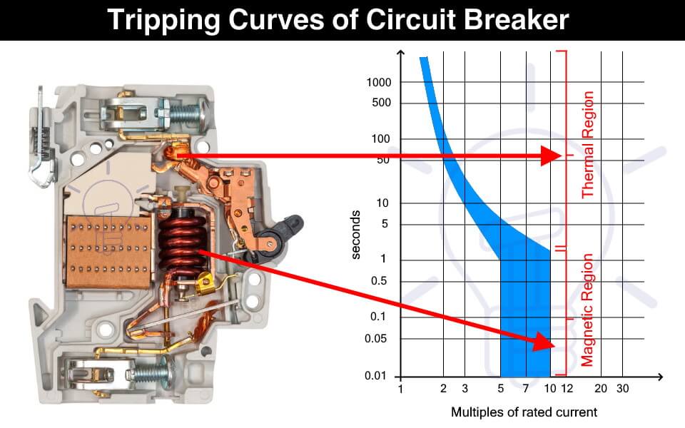
The circuit breaker instantly cut off the power supply to reduce further damage. A circuit breaker has two types of tripping unit i.e. thermal and magnetic tripping unit.
Thermal Tripping Unit: the thermal tripping unit is used for protection against overloading. It uses a bi-metallic contact that bends with a change in temperature. The current flowing through the bimetallic strip heats up contact & trip the circuit breaker.
The rate of bending of the bi-metallic strip depends on the amount of current. Therefore, greater the overloading current, faster the circuit breaker trips.
Magnetic Tripping Unit: The magnetic trip unit is used for protection against short circuit current. it includes a solenoid that produced a strong magnetic field due to high short circuit current to instantly trip the circuit breaker.
Related Posts:
- MCB (Miniature Circuit Breaker) – Construction, Working, Types & Applications
- MCCB (Molded Case Circuit Breaker) – Construction, Types & Working
What is a Trip Curve?
A trip curve also known as a current time graph is a graphical representation of the response of a circuit breaker. It shows the current relationship with the tripping time of a protection device.
Why We Need Different Tripping Curves?
Circuit breakers are used for tripping the power supply as quickly as possible in case of overcurrent. But it should not trip so fast & unnecessary that it becomes a problem.
The overcurrent can happen under normal conditions such as the inrush current of a motor. Inrush current is the huge current draw during the starting of a motor that causes voltage dips in the main line. The circuit breaker should be able to tolerate the inrush current & it should provide some delay before tripping.
Therefore, the circuit breaker selected should not trip so fast that it creates a nuisance & it should not trip so late that it causes any damage. This is where the tripping characteristics of the circuit breakers come into play.
The tripping curve tells how fast a circuit breaker will trip at a specific current. The different tripping curves classify the circuit breakers into categories where each category is used for specific types of loads. It is essential to select a circuit breaker that provides the necessary overcurrent protection.
- Types of Circuit Breakers – Working and Applications
- Air Circuit Breaker (ACB): Construction, Operation, Types and Uses
How to read a Trip Curve?
The following figure shows a chart of a trip curve.
The horizontal X-axis represents the multiples of the current flowing through the circuit breaker. While the Y-axis represents the tripping time of the circuit breaker on a logarithmic scale.

The thermal region shows the response of the bimetallic contact trip unit during overcurrent. The curve shows that the circuit breaker’s tripping time reduces with an increase in the current. The first curve in the graph shows the response of a thermal trip unit.
While the magnetic region shows the response of the solenoid to fault current such as a short circuit current.
As seen from the graph, a circuit breaker does not have a fixed tripping time and we cannot predict an exact tripping point. It is because the tripping is affected by ambient conditions such as temperature. Think of it as a Schrödinger’s Cat area, we do not know when the tripping will occur unless the event happens.
Types of Circuit Breaker Based on Tripping Curves
The circuit breakers are classified into the following five types based on their tripping curves.

Such type of circuit breaker is designed to instantly trip when the operating current is 3 to 5 times its rated current. Their tripping time falls between 0.04 to 13 seconds. They are suitable for domestic applications where surges are very low such as lighting & resistive loads.

They are sensitive and must not be used in places where the normal surges keep on tripping it unnecessarily.
Type C circuit breaker trips instantly at current surges 5 to 10 times its rated current. its tripping time lies between 0.04 to 5 seconds. As they can tolerate higher surge currents, they are used in commercial applications such as the protection of small motors, transformers, etc.

Type D circuit breaker trips instantly when operating current reaches 10 to 20 times its rated current. Its tripping time is 0.04 to 3 seconds. Such circuit breakers can tolerate the high inrush current of large motors. Therefore, they are suitable for running heavy loads in industrial applications.

Such type of circuit breakers trips at 10 to 12 times its rated current with a tripping time of 0.04 to 5 seconds. These circuit breakers are also used for heavy inductive loads in industrial applications.

Type Z circuit breakers are the most sensitive circuit breaker that instantly trips when the operating current reaches 2 to 3 times its rated current. They are used for sensitive equipment that requires very low short circuit trip settings.

- Main Difference between Fuse and Circuit Breaker
- Difference Between MCB, MCCB, ELCB and RCB, RCD or RCCB Circuit Breakers
- How to Read MCB Nameplate Data printed on it?
- How to Find the Proper Size of Circuit Breaker? Breaker Calculator and Examples
- HVDC Circuit Breaker – Types, Working and Applications
- Can We Use AC Circuit Breaker for DC Circuit and Vice Versa?
- Electronic Circuit Breaker – Schematic and Working
- Smart WiFi Circuit Breaker – Construction, Installation and Working
- Why Circuit Breaker Capacity Was Rated in MVA and Now in kA and kV?
- How to Wire 120V and 240V Main Panel? Breaker Box Installation – US – NEC
- How to Wire Single-Phase, 230V Consumer Unit (Breaker Box) with RCD? IEC, UK and EU
This Post has been published by WWW.ELECTRICALTECHNOLOGY.ORG.
Electrical Technology
Related articles.

A Complete Guide About Solar Panel Installation. Step by Step Procedure with Calculation & Diagrams

How to Calculate the Battery Charging Time & Battery Charging Current – Example

Automatic UPS / Inverter Connection Diagram to the Home Panel Board

How to Find the Proper Size of Wire & Cable: Metric & Imperial Systems

Automatic Street Light Control Circuit using LDR & Transistor BC 547

Emergency LED Light Circuit – DP-716 Rechargeable 30 LED’s Lights Schematic
One comment.
Do we have to consider the tripping curves for DIY installation?
Leave a Reply Cancel reply
Your email address will not be published. Required fields are marked *

ELECTRICAL CLASSROOM
A complete Electrical Engineering portal
MCB Trip Curves – B, C, D, K, and Z trip curves
MCB (Miniature circuit breaker) is a re-settable device designed to protect a circuit from short circuits and overcurrents. The trip curve of an MCB (B, C, D, K, and Z curves) tells us about the trip current rating of Miniature Circuit breakers. The trip current rating is the minimum current at which the MCB will trip instantaneously. It is required that the trip current must persist for 0.1s.
Class B trip curve
Class c trip curve, class d trip curve, class k trip curve, class z trip curve, class a trip curve, importance of mcb trip curve types, trip curves for other circuit breakers.
The MCB trip curves, also known as I-t tripping characteristic consist of two sections viz, overload section and short circuit section. Overload section describes the trip time required for various levels of overload currents and the short circuit section describes the instantaneous trip current level of MCB.
Read More: Miniature Circuit Breaker (MCB) – Principle of operation
The MCB with class B trip characteristics trips instantaneously when the current flowing through it reaches between 3 to 5 times the rated current. These MCBs are suitable for cable protection.
MCB with class C trip characteristics trips instantaneously when the current flowing through it reaches between 5 to 10 times the rated current. Suitable Domestic and residential applications and electromagnetic starting loads with medium starting currents.
MCB with class D trip characteristics trips instantaneously when the current flowing through it reaches between Above 10(excluding 10) to 20 times the rated current. Suitable for inductive and motor loads with high starting currents.
MCB with class K trip characteristics trips instantaneously when the current flowing through it reaches between 8 to 12 times the rated current. Suitable for inductive and motor loads with high inrush currents.
MCB with class Z trip characteristics trips instantaneously when the current flowing through it reaches between 2 to 3 times the rated current. These types of MCBs are highly sensitive to short circuits and are used for the protection of highly sensitive devices such as semiconductor devices.

MCB with class A trip characteristics trips instantaneously when the current flowing through it reaches between 2 to 3 times the rated current. Like Class Z MCBs, these are also highly sensitive to short circuits and are used for the protection of semiconductor devices.
MCBs with trip curve class B and trip curve class C is the most commonly used ones. MCBs with Class C trip curves can be found in the lighting power distribution boards in residential and commercial buildings. It trips as soon as the current rises between 5 to 10 times its rated current. Class B MCBs are used in the protection of electronic devices such as PLC, DC power supplies, etc. in control panels. It trips as soon as the current rises between 3 to 5 times its rated current.
In some applications, frequent current peaks occur for a very short period (100ms to 2s). For such applications, class Z-type MCBs shall be used. Class Z-type MCBs are used in circuits with semiconductor devices.
It is important to choose an appropriate MCB current rating and trip curve in order to safeguard the circuit from damage during faults. Hence it is necessary to calculate the short circuit current and inrush current before choosing an appropriate MCB rating. If the chosen MCB rating is much higher than required, then it may not trip in the event of a fault. Similarly, if the MCB is underrated, then it may cause nuisance trips, for example even the starting currents or inrush currents may trip the MCB.
External selection tool: https://new.abb.com/low-voltage/solutions/selectivity/tools-support/curves
All circuit breakers, such as MCCB, ACB, VCB, etc have their own trip characteristics. The only thing is that may not follow the categorization as that of MCB. Also, the circuit breaker curve types are not the same for all types of circuit breakers. It varies from one circuit breaker type to the other and depends on many design factors.
Learn more about MCB:
- What is an MCB?
- Miniature Circuit Breaker (MCB) – Principle of operation
- What is kA rating of MCB and MCCB?
Related Articles: 1. Difference between MCB and MCCB 2. Difference between contactors and relays 3. Difference between Soft Starters and VFDs 4. Difference between MCCB and RCCB 5. Difference between MCB and RCBO 6. Difference between RCCB and RCBO 7. Difference between MPCB and MCCB
27 thoughts on “MCB Trip Curves – B, C, D, K, and Z trip curves”
Very good explanation. I understood the concept. Thank you.
Thank you, Mr. Sanket. Kindly browse through our articles. Please subscribe or follow us on twitter/facebook for instant updates.
Thankhs google team good explace thanks again
Very good mcb make , what Amps load trip make
Very good. Nice explain.. Good job
Explanation is good but your second paragraph doesn’t match the charts. It looks like it is the B-curve that trips between 3-5 times its rated current, and C-curve that trips between 5-10 times its rated current.
Very good, thanks
very good …..thanks
Thanks very much
Very good explanation
Is this curves is applicable to Rccb ?
No. These curves are applicable for mcbs only.
Thanks for your information
The information about mcb is very useful and helpful for a technician, many many thanks for sharing your information.
Great information, I got to know a few more details out of what I wanted to know.
Which type is better choice for UPS protection?
The explanations are very good but in the video is a mistake at minute 0.38. The short circuit sections with the overload section are reversed.
Good for selection of MCB’s
On the c type Mcb on the time curves at a short circuit fault current at 220amp it shows dis connection at 6/7seconds are you saying that disconnection will be instant at this current or 6/7 seconds.
I use B-curve in my home when short circuit occured in the appliace MCB tripped but my appliance burned. My appliance lead wires were shorted by a metal piece was lying on it.I thought MCB could have protected but not. And I also headed big noise of it.
Sorry to hear that. This could be because the MCB was oversized: Much higher than the rated current of the appliance or the MCB could be faulty. We suggest you replace it with a new one. Make sure that you are choosing the right one.
Thanks for sharing such an informative article about MCB.
sir Type C is used for average current load. Type B and C are the most commonly used in DBs. Tripping of MCB Type C is 5-10 times higher than normal. eg: if a 6A mcb put in acircuit , the rated current is 6 A , then how ever the type c mcb with stand 5 to 10 times higherr than normal .
hello, what about the CL curve mcb, because in my home installation I used the cl4 code on the mcb
Perhaps you are referring to product name of the MCB and not its trip curve.
The information is quite educative. Thank you so much
Leave a Comment Cancel reply

Understanding Miniature Circuit Breaker (MCB) Types and Tripping Curves
- by Bhekusizi Dhlodhlo
- Categories: Blog

Table of Contents
Introduction.
Miniature circuit breakers (MCB) provide protection against short circuits and are rated normally up to 125A. They can be combined with a residual current device, to provide protection against short circuits, overloaded circuits and ground faults.
MCB’s tripping characteristics are represented graphically in a trip curve. The curve shows the response of the thermal and magnetic trip element to various overload and short circuit situations.
Those curves are designated letters according to the circuit breaker type. The circuit breaker Types are B, C, D, K and Z corresponding to similar lettered circuit breaker curves.
Why so many different circuit breaker types?

Circuit breaker curves determine the breaker's reaction time to faults. They're the first line of defence against electrical faults. Learn how to select the correct one! 🛡️ #SafetyFirst #ElectricalEngineering #SparkyCalc Tweet
There so many reasons why we need different circuit breaker types with different trip curves and some of the main reasons are:
Selective Coordination
Different electrical components within a system might have varying levels of fault currents they can handle before tripping.
By using different tripping curves, we can ensure that only the faulty component is disconnected during a fault, allowing the rest of the system to remain operational.
This selective coordination can be achieved by use of circuit breakers with different tripping curves in a system. We discuss this in more detail in our blog on understanding circuit breaker co-ordination
Equipment Protection
Different types of equipment have different thermal and electromagnetic characteristics. A more sensitive trip curve might be suitable for protecting sensitive electronic equipment, while a less sensitive one may be appropriate for heavy-duty machinery. This ensures that the protection device responds appropriately to the specific needs of the equipment.
Start-Up and Inrush Currents
Some devices such as large motors experience higher currents during startup or inrush periods. A circuit breaker that allows the flow of high inrush current without tripping can be used in this instance
Fault Types
Different fault types, such as short circuits and overloads, require distinct response times and current thresholds. Circuit breakers with different tripping curves can be used to address these specific fault conditions appropriately.
Safety and Personnel Protection
Human safety is a critical concern. Tripping curves can be designed to quickly disconnect power in situations where personnel might be at risk, while also preventing unnecessary tripping due to minor fluctuations.
Reading Trip Curves

Reading a Trip curve is not that difficult, give me a sec and I’II explain it to you.

A typical tripping curve is shown above. The horizontal X-axis represents the multiples of the current flowing through the circuit breaker. While the Y-axis represents the tripping time of the circuit breaker on a logarithmic scale. A log scale is used so as to fit a wider range of values on the axis.
The top part of the curve is the thermal section of the trip curve’s responds to overloads which are sustained or long-lasting overcurrent conditions.
Therefore, a circuit breaker with a thermal trip curve is better suited for high-inrush current applications. The thermal trip curve is typically curved, reflecting the fact that the response time of the circuit breaker increases as the level of overcurrent increases. The thermal trip unit responds relatively slowly yet consistently.
The second part of the curve is the magnetic current section of the trip curve responds to short circuits. It relies on a magnetic coil or solenoid opening when the overcurrent’s design limit is reached.
The magnetic trip curve is typically a straight line, reflecting the fact that the response time of the circuit breaker is nearly instantaneous for high levels of current.
The bottom part of the time-current curve shows the performance of the instantaneous trip component (short circuit) of the circuit breaker.
The maximum clearing time (time it takes for breakers to completely open) decreases as current increases. This is because of the blow-apart contact design which utilizes the magnetic field built-up around the contacts.
Breaker types and their trip curves
Now that we’ve learned how to read a trip curve, let’s explore how the type of breaker is linked to these curves and what these curves actually mean.
The first type of circuit breaker that we will look at is the Type B.

Type B circuit breakers have relatively fast tripping characteristics. They are designed to protect sensitive and low-power circuits, such as lighting circuits and some electronic devices.
The standards state that these breakers trip at 4 times the rated current but MCB’s being mechanical devices are not that exact and will trip anywhere between 3 to 5 times the rated current. The tripping characteristics of this circuit breaker is called a B Curve.

The next one on our list is the Type C circuit breaker.

Type C circuit breakers have medium tripping characteristics. They are commonly used in applications like small motors, small transformers, and general domestic applications where a moderate level of inrush current is expected during normal operation.
These breakers provide a balance between protecting against overcurrents and allowing for some temporary overloads. The standards state that they should trip at 7.5 times the rated current but will trip anywhere between 5 to 10 times the rated current. The tripping characteristics of this circuit breaker is called a C Curve.

Next we will discuss the Type D circuit breaker.

Curve D circuit breakers have a delayed tripping characteristic. They are often used in applications with high inrush currents, such as large motors, industrial equipment, and power distribution systems.
These breakers can handle significant overcurrents for a longer time before tripping, which is suitable for equipment that experiences frequent startup surges.
The standards state that they should trip at 12.5 times the rated current but will trip anywhere between 10 to 20 times the rated current. The tripping characteristics of this circuit breaker is called a D Curve.

Lets move on to Type K. This circuit breaker is specifically designed for air conditioning and heat pump systems, which often experience high inrush currents during compressor startup.
Type K provides a delayed response to accommodate these inrush currents while still providing protection against sustained overcurrents. These trip at 8 to 12 times the rated current. The tripping characteristics of this circuit breaker is called a K Curve.

Finally we have Type Z. This circuit breaker is used for specialized applications where the tripping time is extremely fast, even faster than Type A.
It’s often used in situations where human safety is the primary concern, such as in some elevator systems or medical equipment. This circuit breaker trips at 2 to 3 times the rated current. The tripping characteristics of this circuit breaker is called a Z Curve.

Rounding Up
I encourage you to reflect on your current or upcoming projects. Are you using the most appropriate type of MCB? Could a different tripping curve offer better protection or efficiency? If you’re unsure, review the technical aspects we’ve discussed, or consult with a professional.
Your thoughts and experiences are invaluable to this discussion. Please contact me for further discussions. Let’s continue to learn and grow together in our understanding of electrical systems. For more insights, check out similar topics on our blog page and home page . And for updates, don’t forget to subscribe to our newsletter.
How useful was this post?
Click on a star to rate it!
Average rating 5 / 5. Vote count: 1
No votes so far! Be the first to rate this post.
Browse some of our featured calculators
Subscribe to our newsletter, get updates and learn from the best, related blogs, want to know when we have new content, i’m here to assist you.
Something in this article isn’t Clear? Feel free to contact me, and I will be more than happy to answer all of your questions.
Share this post

My name is Bheki and I’m an Electrical Engineer. I have a passion for engineering and teaching/mentoring. Qualifications: BEng (Electronic) Hons, MIEAust, CPEng, NER, APEC Engineer IntPE(Aus), RPEQ.
Keep Reading
Copyright © 2024. All rights reserved.
Lets share the love
Recent Orders
Your account.
Checkout $0.00
- Product Returns (RMAs)
- Pay Proforma Invoices
- Pay Freights
- Invoices / Invoice Reprint
- Quotes / Favs / BOMs
- Packing List Reprint
- My Product Docs
- Credit Application
- Barcode / RFID / Vision
- Bulk Wire & Cable
- Cables (Terminated)
- Circuit Protection / Fuses / Disconnects
- Communications
- Drives & Soft Starters
- Enclosure Thermal Management & Lights
- Enclosures & Racks
- HMI (Human Machine Interface)
- Hydraulic Components
- Motion Control
- Motor Controls
- Pneumatic Components
- Power Products (Electrical)
- Power Transmission (Mechanical)
- Process Control & Measurement
- Programmable Controllers
- Pushbuttons / Switches / Indicators
- Relays / Timers
- Sensors / Encoders
- Stacklights
- Structural Frames / Rails
- Tools & Test Equipment
- Water (Potable) Components
- Wiring Solutions
- Retired Products
- E-newsletter
- Online PDF Catalog
- Order Catalog On USB
- Download Price List
- Video Tutorials
- Company Reviews
- Job Opportunities
- Product Application Stories
- Learning Library
- Affordable Training
- Free Online PLC training
- Find an authorized integrator
- Track Your Order
- Pay Open Invoices
- Product Comparison Feature - How To Video
- Cybersecurity
- Programmable Logic Controllers
- Productivity1000 PLCs
- Productivity2000 PLCs
- Productivity3000 PLCs
- ProductivityCODESYS
- LS Electric XGB Series PLCs
- ProductivityOpen
- Do-more H2 PLCs or Do-more T1H Series
- Do-more BRX PLCs
- C-more Touch Panels
- AC & DC Drives
- PLC Family Selector
- P1000 PLC Systems
- P2000 PLC Systems
- P3000 PLC Systems
- CLICK PLC Systems
- Do-more ® BRX PLC Systems
- LS-Electric ® XGB PLC Systems
- Productivity ® Open Systems
- Datalogic ® Safety Light Curtains
- LS-Electric ® Servo Systems
- Nitra ® Pneumatic Grippers
- Object Detection (Sensors)
- PAL Controller Configurator
- Precision Gearbox Selector
- Protos X ® Field I/O
- Quadritalia ® Modular Enclosures
- Stellar ® Soft Starters
- Stepper System Selector
- SureFrame T-slot Extrusion
- SureMotion ® XYZ Gantry
- SureServo2 ® System Selector
- SureStep ® Linear Actuators
- Timing Belts & Pulleys
- Werma ® Stacklights
What is a Trip Curve? Understanding Circuit Breaker Trip Curves From AutomationDirect

https://www.AutomationDirect.com/circuit-protection (VID-CP-0009) Circuit breaker and fuse trip curves (CB Trip curves) explain how a trip occurs based on current and time. Example: A Curve B Curve C Curve D Curve
AutomationDirect carries a full selection of industrial circuit protection devices with incredible prices, high stock rates and fast shipping. Trip curves may be called tripping characteristics, current curve, current-time curve or other terms. A trip curve is simply a description of how an overcurrent based on time will trip a fuse or circuit breaker. For this video we’ll focus on breakers but the same applies to fuses. You may see breakers sold based on trip curve. Looking at the curve chart, this axis is time and this one is amperage as a multiple of rated current. It’s obvious at a glance that the lower the current the longer it takes to trip. This is common for most breakers and fuses. The intended use of the device determines the desired curve. This curve has 3 different curves in one chart because the breakers for this chart are available in B, C or D curves. Lets look at the range of typical motor inrush. This is usually 6 – 8 times the motor FLA. We can see on a B or C curve this amount of current would trip the breaker well under .01 seconds. This would not be enough time for a motor to start and the current to come down. But on the D curve this gives us at least 1 second which should be plenty of time for the inrush to subside. So, as you can see D curve breakers are intended of highly inductive loads like motors or transformers. The faster acting B curve is used for resistive loads which have little to no inrush and the C curves are used where only limited inductive loads are present such as lighting or control circuits. Whether you prefer circuit breakers, fuses, disconnect switches or other types of circuit protection, Automation Direct is your common sense way to buy industrial controls. If you need more assistance please see our free tech support options here. We have a vast library of other videos please click here to view all product videos. Click here to subscribe to our YouTube channel for upcoming products and solutions.
Company Information

Voted #1 mid-sized employer in Atlanta Check out our job openings
Characteristics of Circuit Breaker Trip Curves and Coordination
Time-current curves are graphical representations of the trip characteristics of a circuit breaker. These curves show the relationship between the magnitude of the current flowing through the circuit breaker and the time it takes for the circuit breaker to trip.
This information is critical for ensuring that the circuit breaker provides adequate protection for the equipment it is connected to. Time-current curves are typically provided by the manufacturer of the circuit breaker and are based on industry standards such as the Institute of Electrical and Electronics Engineers (IEEE) and the National Electrical Manufacturers Association (NEMA).
How to read a Time-current Curve
Time-current curves are typically shown on a log-log plot. Figures along the horizontal axis of the curve represent the continuous current rating (In) for the circuit breaker, figures along the vertical axis represent time in seconds.
To determine how long a breaker will take to trip: find the current multiple of (In) at the bottom of the graph. Next, draw a vertical line to the point where it intersects the curve and then draw a horizontal line to the left side of the graph to find the trip time.

The total clearing time of a circuit breaker is the sum of the breaker’s sensing time, unlatching time, mechanical operating time and arcing time.
Curves are developed using predefined specifications such as operation at an ambient temperature of 40°C, so keep in mind that the actual operating conditions of the circuit breaker can cause variations in its performance.
Most curves have an information box that will define which circuit breaker the curve applies to. This information box may also contain important notes from the manufacturer such as the allowable deviation from trip times.

Overload Protection
The upper portion of the time-current curve shows the circuit breaker’s thermal response, the curved line indicates the nominal performance of the circuit breaker.
In thermal magnetic breakers, a thermal overload occurs when a bi-metal conductor inside the circuit breaker deflects after becoming heated by the load current, de-latching the operating mechanism and opening the contacts.
The larger the overload, the faster the bi-metallic strip will heat up and deflect to clear the overload. This is what is known as an “inverse time-curve.”
Long-Time Function
In electronic circuit breakers, the long-time function (L) simulates the effect of a thermal bi-metal element. The nominal pickup point where an electronic trip unit senses an overload is roughly around 10% of the selected ampere rating. Once picked up, the circuit breaker will trip after the time specified by the long-time delay adjustment has been achieved.
Short Circuit Protection
The lower portion of the time-current curve displays the short circuit response of the circuit breaker. In thermal magnetic breakers, tripping place when overcurrent’s of significant magnitude operate a magnetic armature inside of the circuit breaker which de-latches the mechanism.
Instantaneous Function
In electronic circuit breakers, the Instantaneous (I) function simulates the magnetic characteristic of a thermal-magnetic circuit breaker. This is achieved through the microprocessor which takes samples from the AC current waveform many times a second to calculate the true RMS value of the load current. Instantaneous tripping occurs with no intentional time delay.

Short-Time Function
Some electronic circuit breakers may be equipped with a Short-time function (S) which gives the circuit breaker a delay before tripping on a significant overcurrent. This allows for selective coordination between protective devices to ensure that only the device nearest to the fault open, leaving other circuits unaffected (see circuit breaker coordination below).
The I 2 t characteristic of the short time function determines the delay type. I 2 t IN will result in an inverse-time delay that resembles the time/current characteristics of fuses. This is similar to the long time function except with a much faster delay. I 2 t OUT provides a constant delay, usually 0.5 seconds or less as noted on the time-current curve.
Zone Interlock Function
Circuit breakers equipped with zone interlocking on short delay with no restraining signal from a downstream device will have the minimum time band applied regardless of setting, this is sometimes referred to as the maximum unrestrained delay.
When the instantaneous function is disabled, a short-time delay override is used to instantaneously trip circuit breakers in the event of a significant short circuit. This is called the short-time withstand rating and is represented on the trip curve as an absolute ampere value.
Related: Zone Selective Interlocking (ZSI) Basic Principles
Ground Fault Protection
Like the long-time function, the ground fault (G) element consists of a pickup and delay setting. When a phase-to-ground fault occurs, the sum of the phase currents are no longer be equal because the ground fault current returns through the ground bus. In a 4-wire system a fourth CT is installed on the neutral bus to detect this imbalance.
When a current imbalance occurs, the circuit breaker will pick up if the magnitude exceeds the ground fault pickup setting. If the breaker remains picked up for the time specified by the ground fault delay, the circuit breaker will trip. Ground fault protection is sometimes supplied with an I 2 t function which operates under the same principle as short-time delay.

Ground fault protection requires the least energy to trip the circuit breaker, often times with trip values set well below the long time pickup setting. When testing the overload or short circuit function of a circuit breaker, the ground fault protection will need to be disabled or “moved out of the way” for other functions to operate.
Use of the manufacturer’s test kit or rewiring the neutral CT input is the preferred method of primary-injection testing on a low voltage circuit breaker with ground fault protection, otherwise two poles can be connected in series to provide balanced secondary currents to the trip unit.
Related: Ground Fault Protection Systems: Performance Testing Basics
Circuit Breaker Coordination
Time-current curves are essential for the proper coordination of circuit breakers. In the event of a fault, only the circuit breaker closest to the fault should operate, leaving other circuits unaffected.
In the example below, three circuit breakers have been coordinated so that the tripping time of each breaker is greater than the tripping time for the downstream breaker(s) regardless of the fault magnitude.

Circuit breaker CB-3 is set to trip if an overload of 2000A or greater occurs for 0.080 seconds. Circuit breaker CB-2 will trip if the overload remains for 0.200 seconds, and circuit breaker CB-1 if the fault remains for 20 seconds.
If the fault occurs downstream of breaker CB-3 it will trip first and clear the fault. Circuit breakers CB-2 and CB-1 will continue to provide power to the circuit.
Each function of the trip unit should also be coordinated to prevent nuisance trips. If a circuit breaker is feeding a piece of equipment with large inrush currents for example, the instantaneous pickup value should be set higher than the short time pickup value to prevent tripping when the equipment is energized.
Related: Electrical Power System Coordination Studies Explained
References:
- Trip Curves and Coordination, Square D Data Bulletin 0600DB0105
- Basics of Circuit Breakers: Siemens STEP Series

- Popular Topics
- Latest Topics
- Forum Archive
- News and Announcements
- Articles & Guides
- Electrical Testing Talk
- Productivity Tools
- Webinar Agenda
- Industry Links
- Terms Library
Certification Training
- Practice Exams
- ETT Study Guide
- QEMW Study Guide
- CET Study Guide
- Recommended Reading
- Certification Archive
- Start Your Career
- Connect & Discuss
Help and Support
- How to Sign Up
- User Guidelines
- Privacy Policy
- Terms of Service
- All Help Topics
Popular Topic Tags
This website is not affiliated with, maintained, authorized, endorsed or sponsored by the International Electrical Testing Association (NETA) or any of its affiliates. The information presented on this website should not be used to replace any kind of classroom or group study led by a certified instructor. The use of all copyrighted material on this website is provided for the purposes of teaching, scholarship, and research, and is therefore considered to be covered as "fair use" as specified in 17 USC § 107 - Limitations on exclusive rights: Fair use. If you are the owner of copyrighted material on this website and feel that our use of such material is not covered under 17 USC § 107, please contact us. TestGuy.net is a participant in the Amazon Services LLC Associates Program, an affiliate advertising program designed to provide a means for sites to earn advertising fees by advertising and linking to amazon.com. Copyright © 2024 TestGuy.net. All rights reserved.
What you need to know about miniature circuit breaker trip curves
One of the critical criteria when selecting miniature circuit breakers is their trip curve. Awareness of these curves will help you select the right breakers for your applications, and diagnose potential nuisance tripping issues.
Trip curve basics Electrical protection devices, with virtually no exceptions, operate based on a simple formula: If THIS, then THIS. If this limit reaches a certain level, then the device executes the designed or programmed action. Today’s large, molded-case circuit breakers may include algorithms consisting of a complex set of If/Then parameters. Miniature circuit breakers (MCBs), on the other hand, operate based on only two parameters: overload and short-circuit.
Still, even with these two basic parameters, breaker buyers face a broad selection of miniature circuit breakers that could potentially meet their application requirements. Selecting the optimum miniature circuit breaker is critical to helping ensure proper protection, with minimal or no nuisance tripping, at the lowest possible cost. Making the right selection requires an understanding of the basics of trip curves.
Understanding trip curves Most protective devices have a defined trip curve, also referred to as a time/current curve, that describes the behavior of the device. The curve is literally a graphic representation of how the device will respond to changes in current. From a functional perspective, the curve parameters specify the high and low current thresholds that will cause the device to trip.
Selecting the appropriate trip curve achieves a good balance between overcurrent protection and optimal machine operation. A fast-acting trip curve will do an excellent job of circuit and production equipment/load protection, but at the cost of frequent and costly nuisance tripping (mostly due to inrush currents of motors and transformers). Choosing a breaker with higher trip points or thresholds will better keep the process up and running, but might cause more temperature rise in cables/conductors and connected loads.
Trip curves are defined by IEC standards 60898-1 and 60947-2. The curves actually represent two different trip functions within the miniature circuit breaker – thermal and electro-magnetic. The thermal section (top section of the chart) that responds to overloads typically consists of a bi-metallic strip. The response of the thermal trip unit is relatively slow. The thermal section, which also complies with UL standards in addition to the before-mentioned IEC standards, is similar across all trip curves.
The short-circuit section (bottom) relies on a magnetic coil or solenoid that opens if the overcurrent design limit is reached. This section of the breaker responds within milliseconds. This characteristic of the trip curve has no counterpart on the UL side.
Trip curve origins The concept of trip curves originated in the IEC world. The alphabetic code used to categorize miniature circuit breakers (B, C, D, K, and Z) carried over from IEC standards. The standard defines the lower and upper thresholds for tripping, but manufacturers have the flexibility to decide the precise specifications within those thresholds that will cause a trip in their products. The trip curve graph shows the tolerance band within which manufacturers can set the individual tripping point of their breakers.
The characteristics and applications of each curve, from most- to least-sensitive are: Z: Trips at 2 to 3 times rated current. Suitable for highly sensitive applications, e.g., semiconductor devices. B: Trips at 3 to 5 times rated current. C: Trips at 5 to 10 times rated current. Suitable for medium inrush currents. K: Trips at 10 to 14 times rated current. Suitable for loads with high inrush currents, mostly for use with motors and transformers. D: Trips at 10 to 20 times rated current. Suitable for high starting currents.
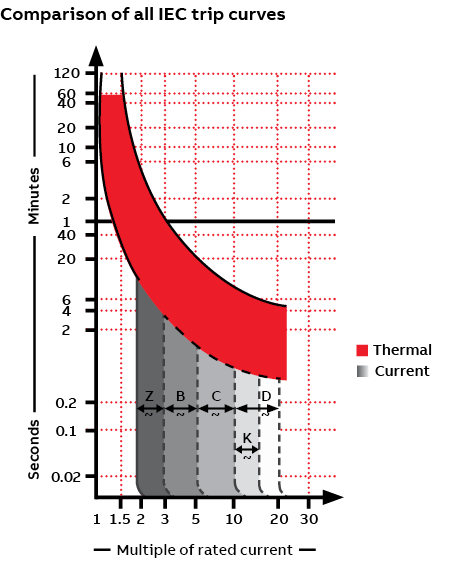
Referring back to the “Comparison of all IEC trip curves” graph, you can see that higher currents trigger more rapid trips.
The ability to tolerate inrush current is an important consideration in trip-curve selection. Certain loads, notably motors and transformers, experience a momentary change in current, the inrush current, at contact closure. Faster protective devices, like a B-trip curve, would see this inrush as a fault and open the circuit. For these types of loads, trip curves with a higher magnetic tripping point, either D or K, can “ride through” the momentary inrush of current, protecting the circuit without nuisance tripping.
Choosing the right trip curve The availability of a range of trip curves and options for different current levels within each range enables selection of an appropriate breaker to protect a variety of loads in various applications.
With large, molded case circuit breakers , you can select one of a number of breakers and then adapt it to the application by adjusting its operating parameters. The same isn’t true for miniature circuit breakers. Their operating parameters are fixed, making it critical that you select the breaker to meet the required specs, including the appropriate trip curve for the application.
Armed with the operating values for a circuit or application/load, it’s possible to make a good selection of the appropriate trip curve. However, this may require some trial and error to arrive at the optimum breaker. Recurring nuisance tripping may be a sign an alternate may be a better fit.
To help ensure the optimal balance between protection and minimal nuisance tripping, the best approach may be to consult with the device manufacturer or distributor. Provide them with the details of your application, and they should be able to recommend the right miniature circuit breakers to meet your needs.
— Thomas Weinmann Senior Product Marketing Manager
ABB Electrification Business
Presented by:
This site is created by ABB application engineers and experts as an educational tool to help engineers.

800-999-7378

- All blog posts
In this industrial blog, learn how to make your technology systems work for you . Become faster, smarter, competitive, and cost-effective in today's rapidly changing marketplace by learning from our experts' collective experience. Bookmark our page (or better yet, subscribe ) because we post new articles every Thursday!

Circuit Breaker Trip Curves: What Electrical Control Panel Builders Need to Know

Editor's note: This blog has been updated April 2024 for comprehensiveness
Circuit breakers are essential devices in electrical systems, protecting against harmful overcurrent conditions. An improperly-selected circuit breaker causes, at best, nuisance tripping . At worst, it causes damage to electrical equipment, electrical fires, and serious or fatal injuries. A critical factor in selecting circuit breakers is understanding the trip curve , which visually represents how quickly it will trip or open in response to different levels of overcurrent. But trip curves are notoriously confusing, so keep reading to learn the basics of trip curves to select the most appropriate and cost-effective breaker for your application.
Skip to a Section
What are Trip Curves? | Trip Curve Types | UL 1077 or UL 489? | How to Choose
What are Trip Curves?
Circuit breaker trip curves are graphical representations of the response time of a circuit breaker to overcurrent conditions. They show the relationship between the level of current flowing through a circuit and the time it takes for the circuit breaker to trip or interrupt the current. An example of a trip curve is shown below.

The trip curve helps electrical control panel builders understand how a circuit breaker will behave under different fault conditions, such as overloads or short circuits. By matching the trip curve with the characteristics of the application, electrical control panel builders can select the correct size and type of circuit breaker, with minimal or no nuisance tripping, at the lowest possible cost.
Trip Curve Types

Thermal Region of Trip Curve
The thermal section of the trip curve responds to overloads (sustained or long-lasting overcurrent conditions) and is represented by the top/red area of the left graph. Therefore, a circuit breaker with a thermal trip curve is better suited for high-inrush current applications. The thermal trip curve is typically curved , reflecting the fact that the response time of the circuit breaker increases as the level of overcurrent increases. The thermal trip unit responds relatively slowly yet consistently.
Magnetic Region of Trip Curve
The magnetic current section of the trip curve responds to short circuits and is represented by the bottom/gray area of the graph above. It relies on a magnetic coil or solenoid opening when the overcurrent’s design limit is reached. The magnetic trip curve is typically a straight line , reflecting the fact that the response time of the circuit breaker is nearly instantaneous for high levels of current.
Characteristics of the magnetic/short-circuit trip unit
The characteristics of the magnetic/short-circuit trip unit and applications of each curve, from most to least sensitive, are:
Z : Trips at 2 to 3 times rated current. This is suitable for highly sensitive applications, e.g., semiconductor devices.
B : Trips at 3 to 5 times rated current.
C : Trips at 5 to 10 times rated current, making it suitable for medium inrush currents.
K : Trips at 10 to 14 times rated current. This suits loads with high inrush currents, mostly for motors and transformers.
D : Trips at 10 to 20 times rated current, making it suitable for high starting currents.
Instantaneous Region of Trip Curve
Sometimes, a trip curve will include an instantaneous region. The instantaneous trip curve is usually represented by a vertical line , indicating the maximum current level that the circuit breaker can interrupt without any delay .
What Do UL 1077 and UL 489 Mean?
In addition to trip curves, understanding UL certifications is another key component to selecting circuit breakers. UL-certified circuit breakers are a type of circuit breaker that is certified by Underwriters Laboratories ( UL ) and meets their requirements for construction, performance, and testing.
UL 489 and UL 1077 circuit breakers have different trip curves for specific applications. It is important to note that both standards require passing calibration, overload, endurance, and short-circuit tests, but UL 489 testing is more rigorous than UL 1077 testing . Choosing the appropriate UL-certified circuit breaker with the correct trip curve is vital to ensure proper protection and avoid damage and downtime.
What is UL 489?
UL 489 is a standard for molded-case circuit breakers , which are commonly used in commercial and industrial applications. One of the key features of UL 489 circuit breakers is their ability to interrupt short-circuit currents. This is important because short circuits can generate extremely high currents that can damage equipment and pose a safety hazard. UL 489 circuit breakers are also designed to be reliable and durable, with a long lifespan and minimal maintenance requirements.
What is UL 1077?
UL 1077 is a standard for supplementary protectors , which are commonly used in low-voltage DC or AC circuits. UL 1077 circuit breakers are designed to be compact and cost-effective, making them well-suited for applications where space and budget constraints are a concern. But i t is essential to note UL 1077 devices are not considered circuit breakers by UL and are defined as supplementary protectors.
How to Choose a Circuit Breaker with the Right Trip Curve

Here are four general guidelines to help select the appropriate breaker:
- 1. Identify the load type:
- The load connected to the circuit breaker is an essential factor to consider when selecting the trip curve. For example, loads like motors and transformers have high inrush currents, and a faster-acting trip curve can cause nuisance tripping. Therefore, a circuit breaker with a slower trip curve or a higher magnetic trip point is more suitable for these types of loads.
- 2. Evaluate the expected fault conditions:
- Fault conditions like overloads, short circuits, and ground faults have different characteristics and require other response times from the circuit breaker. Therefore, a circuit breaker with a trip curve that matches the expected fault conditions will provide optimal protection.
- 3. Consider system coordination:
- 4. Consult with the manufacturer or supplier:
- The manufacturer or supplier of the circuit breaker can provide valuable guidance on selecting the appropriate trip curve for a given application. They can also provide information on specific trip curves compatible with the circuit breaker and recommend a suitable trip curve based on the application's requirements.
- In general, understanding trip curves and UL certifications is crucial for selecting the proper protective devices for your electrical applications. If in doubt, a consultation with the manufacturer or value-add distributor, like Airline , can help make an informed decision.
- Have a question? Let us know!

Resources
- Shop Circuit Breakers
- Shop Minature Breakers
- IEC General Rules
- A Guide on UL Standards
- Contact Us!
Topics: Electrical , Explainers
Leave Comment
Subscribe to our blog, most recent, post by topic.
- Explainers (84)
- Product Spotlights (51)
- Electrical (35)
- Automation (32)
- Hydraulics (24)
- Robotics (17)
- Pneumatics (16)
- About Airline (15)
- Maintenance (15)
- Tutorials (14)
- Phoenix Contact (13)
- Framing (12)
- Machine Safety (12)
- Application/Success Stories (10)
- Bosch Rexroth (hydraulics) (10)
- Bosch Rexroth (framing) (7)
- Lean Manufacturing (5)
- Liquid & Gas Prssure (5)
- Lubrication (5)
- Lincoln SKF (4)
- Predictive Maintenance (4)
- Bosch Rexroth (linear) (3)
- Fluid Cleanliness (3)
- Clippard (2)
- Grace Technologies (2)
- Bosch Rexroth (automation and controls) (1)
- Case study (1)
- Compliance (1)
- In-Person Events (1)
- Lab Safety (1)
- QC Conveyors (1)
- Trainings (1)
IMAGES
VIDEO
COMMENTS
A circuit breaker has two types of tripping unit i.e. thermal and magnetic tripping unit. Thermal Tripping Unit: the thermal tripping unit is used for protection against overloading. It uses a bi-metallic contact that bends with a change in temperature. The current flowing through the bimetallic strip heats up contact & trip the circuit breaker.
MCB (Miniature circuit breaker) is a re-settable device designed to protect a circuit from short circuits and overcurrents. The trip curve of an MCB (B, C, D, K, and Z curves) tells us about the trip current rating of Miniature Circuit breakers. The trip current rating is the minimum current at which the MCB will trip instantaneously.
The third part (Chapter 4) describes the trip units of ABB circuit breakers and the characteristic trip curves. Finally, the fourth part (Chapters 5 and 6) provides examples of curves to help comprehension and interpretation of the contained information. Introduction.
https://www.AutomationDirect.com/circuit-protection - (VID-CP-0009) Circuit breaker and fuse trip curves (CB Trip curves) explain how a trip occurs based on ...
the trip curve has no counterpart on the UL side. Trip curve origins The concept of trip curves originated in the IEC world. The alphabetic code used to categorize miniature circuit breakers (B, C, D, K, and Z) carried over from IEC standards. The standard defines the lower and upper thresholds for tripping, but manufacturers have
Time-current curves are shown as bands, and the actual performance of any one breaker can fall anywhere within the band. Using the example CFD6 breaker and 200 ampere trip unit, the time the breaker will trip for any given overload can easily be determined using the same procedure as previously discussed. For example, the breaker will trip ...
Vote count: 1. MCB's tripping characteristics are represented graphically in a trip curve. The curve shows the response of the thermal and magnetic trip element to various overload and short circuit situations. Those curves are designated letters according to the circuit breaker type. The circuit breaker Types are B, C, D, K and Z ...
Every circuit breaker has a characteristic curve that reports the manner in which it trips. As this curve is reporting the amount of current vs time, it is a...
Trip curves may be called tripping characteristics, current curve, current-time curve or other terms. A trip curve is simply a description of how an overcurrent based on time will trip a fuse or circuit breaker. For this video we'll focus on breakers but the same applies to fuses. You may see breakers sold based on trip curve. Looking at the ...
Learn the basics of circuit breaker trip curves by understanding what they are and how we use them.Get the FULL video transcript here: https://www.rspsupply....
Long-Time Function. In electronic circuit breakers, the long-time function (L) simulates the effect of a thermal bi-metal element. The nominal pickup point where an electronic trip unit senses an overload is roughly around 10% of the selected ampere rating. Once picked up, the circuit breaker will trip after the time specified by the long-time delay adjustment has been achieved.
Forty seconds at 2X the rated current is the slowest the circuit breaker will trip (2). The bottom of the chart is for the magnetic trip of the coil/solenoid; 0.02 to 2.5 seconds at 3X the rated current is the soonest the circuit breaker will trip (3). The same duration, 0.02 to 2.5 seconds, at 5X the rated current, is the longest it will take ...
This is due to tolerance of the trip elements in the circuit breaker. The curves below (Figures 12 and 13), will show the differences in this deadband for the same circuit breaker using an electronic versus non-electronic trip mechanism. Notice the difference in the tolerance in the trip curve of the feeder circuit breaker.
A breaker with higher trip points will better keep the process up and running. Trip curves are defined by IEC standards 60898-1 and 60947-2. The curves represent two different trip functions: thermal and electromagnetic. The thermal section (top/red area of the chart) that responds to overloads typically consists of a bi-metallic strip.
Miniature Circuit Breaker (MCB) Trip calculation. First, look for the amperage marking on the switch of the MCB. This is usually between 15 or 20. Also look for the voltage marking on the breaker switch, this will be between 120 or 240. Second, locating the voltage and current rating, multiply the volts and the amps.
The thermomagnetic trip unit consists of two parts: The thermal trip unit - Made up by a bimetal thermal device which actuates the opening of a circuit breaker with a delay depending on the overcurrent value. This trip unit is intended for the protection against overloads. The magnetic trip unit - Made up by an electromagnetic device, with ...
Trip curves are defined by IEC standards 60898-1 and 60947-2. The curves actually represent two different trip functions within the miniature circuit breaker - thermal and electro-magnetic. The thermal section (top section of the chart) that responds to overloads typically consists of a bi-metallic strip. The response of the thermal trip unit ...
3. Consider system coordination: In a system with multiple circuit breakers, it is essential to ensure they coordinate correctly. For example, electrical control panel builders should select the trip curves to provide the downstream circuit breaker trips before the upstream breaker.
Most circuit breakers have two tripping technologies in them which makes the trip curve charts difficult to read. There is a magnetic trip curve for short c...
Short-time pickup is adjustable from 1.5 to 10 times the trip unit ampere setting (Ir). For example, a 1000 ampere frame can be adjusted to trip anywhere from 1500 to 10,000 amps. The switch also has an "OFF" position to eliminate short-time pickup and short-time delay. Short-time pickup used for selective tripping.
How long does it really take a circuit breaker to trip? Let's learn about trip curves (Type B, for example) and time how long it really takes a typical brea...
1.3 Electronic Release. A coil, placed on each conductor, continuously measures the current in each of them. This information is processed by an electronic module which controls the tripping of the circuit breaker when the values of the settings are exceeded. Figure 3 - Typical tripping curve for an electronic release.
Time-Current Curves Protective Device Coordination. Protective Device Coordination Study- Description: An organized time-current study of protective devices from the utility to a device. A comparison of the time it takes protective devices to operate when certain levels of normal or abnormal current pass through them.