- Switch skin
Home > Protection > Tripping Curves of Circuit Breakers – B, C, D, K and Z Trip Curve

Tripping Curves of Circuit Breakers – B, C, D, K and Z Trip Curve
Types of circuit breaker based on its tripping curve.
A circuit breaker is a protection device employed in every electrical circuit to prevent any potential hazard. There are different types of circuit breakers used all over the world due to their various characteristics & applications. It is necessary to have a circuit breaker that offers adequate protection so that one can work safely around it without having fear of any potential hazards. That is why it is best to know about these kinds of circuit breakers & what kinds of protection do they offer before buying one.
Table of Contents
What is a Circuit Breaker?
A circuit breaker is an electrical device that provides protection against fault current. It breaks the circuit in case of overloading & short circuit. The fault currents generated due to these fault conditions can damage the electrical devices as well as cause fire in a building that can also pose danger to human life.
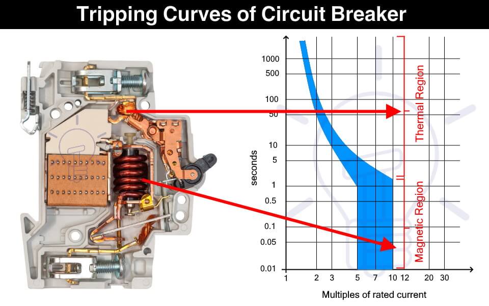
The circuit breaker instantly cut off the power supply to reduce further damage. A circuit breaker has two types of tripping unit i.e. thermal and magnetic tripping unit.
Thermal Tripping Unit: the thermal tripping unit is used for protection against overloading. It uses a bi-metallic contact that bends with a change in temperature. The current flowing through the bimetallic strip heats up contact & trip the circuit breaker.
The rate of bending of the bi-metallic strip depends on the amount of current. Therefore, greater the overloading current, faster the circuit breaker trips.
Magnetic Tripping Unit: The magnetic trip unit is used for protection against short circuit current. it includes a solenoid that produced a strong magnetic field due to high short circuit current to instantly trip the circuit breaker.
Related Posts:
- MCB (Miniature Circuit Breaker) – Construction, Working, Types & Applications
- MCCB (Molded Case Circuit Breaker) – Construction, Types & Working
What is a Trip Curve?
A trip curve also known as a current time graph is a graphical representation of the response of a circuit breaker. It shows the current relationship with the tripping time of a protection device.
Why We Need Different Tripping Curves?
Circuit breakers are used for tripping the power supply as quickly as possible in case of overcurrent. But it should not trip so fast & unnecessary that it becomes a problem.
The overcurrent can happen under normal conditions such as the inrush current of a motor. Inrush current is the huge current draw during the starting of a motor that causes voltage dips in the main line. The circuit breaker should be able to tolerate the inrush current & it should provide some delay before tripping.
Therefore, the circuit breaker selected should not trip so fast that it creates a nuisance & it should not trip so late that it causes any damage. This is where the tripping characteristics of the circuit breakers come into play.
The tripping curve tells how fast a circuit breaker will trip at a specific current. The different tripping curves classify the circuit breakers into categories where each category is used for specific types of loads. It is essential to select a circuit breaker that provides the necessary overcurrent protection.
- Types of Circuit Breakers – Working and Applications
- Air Circuit Breaker (ACB): Construction, Operation, Types and Uses
How to read a Trip Curve?
The following figure shows a chart of a trip curve.
The horizontal X-axis represents the multiples of the current flowing through the circuit breaker. While the Y-axis represents the tripping time of the circuit breaker on a logarithmic scale.

The thermal region shows the response of the bimetallic contact trip unit during overcurrent. The curve shows that the circuit breaker’s tripping time reduces with an increase in the current. The first curve in the graph shows the response of a thermal trip unit.
While the magnetic region shows the response of the solenoid to fault current such as a short circuit current.
As seen from the graph, a circuit breaker does not have a fixed tripping time and we cannot predict an exact tripping point. It is because the tripping is affected by ambient conditions such as temperature. Think of it as a Schrödinger’s Cat area, we do not know when the tripping will occur unless the event happens.
Types of Circuit Breaker Based on Tripping Curves
The circuit breakers are classified into the following five types based on their tripping curves.

Such type of circuit breaker is designed to instantly trip when the operating current is 3 to 5 times its rated current. Their tripping time falls between 0.04 to 13 seconds. They are suitable for domestic applications where surges are very low such as lighting & resistive loads.

They are sensitive and must not be used in places where the normal surges keep on tripping it unnecessarily.
Type C circuit breaker trips instantly at current surges 5 to 10 times its rated current. its tripping time lies between 0.04 to 5 seconds. As they can tolerate higher surge currents, they are used in commercial applications such as the protection of small motors, transformers, etc.

Type D circuit breaker trips instantly when operating current reaches 10 to 20 times its rated current. Its tripping time is 0.04 to 3 seconds. Such circuit breakers can tolerate the high inrush current of large motors. Therefore, they are suitable for running heavy loads in industrial applications.

Such type of circuit breakers trips at 10 to 12 times its rated current with a tripping time of 0.04 to 5 seconds. These circuit breakers are also used for heavy inductive loads in industrial applications.

Type Z circuit breakers are the most sensitive circuit breaker that instantly trips when the operating current reaches 2 to 3 times its rated current. They are used for sensitive equipment that requires very low short circuit trip settings.

- Main Difference between Fuse and Circuit Breaker
- Difference Between MCB, MCCB, ELCB and RCB, RCD or RCCB Circuit Breakers
- How to Read MCB Nameplate Data printed on it?
- How to Find the Proper Size of Circuit Breaker? Breaker Calculator and Examples
- HVDC Circuit Breaker – Types, Working and Applications
- Can We Use AC Circuit Breaker for DC Circuit and Vice Versa?
- Electronic Circuit Breaker – Schematic and Working
- Smart WiFi Circuit Breaker – Construction, Installation and Working
- Why Circuit Breaker Capacity Was Rated in MVA and Now in kA and kV?
- How to Wire 120V and 240V Main Panel? Breaker Box Installation – US – NEC
- How to Wire Single-Phase, 230V Consumer Unit (Breaker Box) with RCD? IEC, UK and EU
This Post has been published by WWW.ELECTRICALTECHNOLOGY.ORG.
Electrical Technology
Related articles.

A Complete Guide About Solar Panel Installation. Step by Step Procedure with Calculation & Diagrams

How to Calculate the Battery Charging Time & Battery Charging Current – Example

Automatic UPS / Inverter Connection Diagram to the Home Panel Board

How to Find the Proper Size of Wire & Cable: Metric & Imperial Systems

Automatic Street Light Control Circuit using LDR & Transistor BC 547

Emergency LED Light Circuit – DP-716 Rechargeable 30 LED’s Lights Schematic
One comment.
Do we have to consider the tripping curves for DIY installation?
Leave a Reply Cancel reply
Your email address will not be published. Required fields are marked *

- Get custom product tools and services
- Access training
- Manage support cases
- Create and manage your orders (authorized partners only)
Schneider Electric USA Website
Time-Current Curves
All trip curves, circuit breaker, where to buy, where to buy.
Easily find the nearest Schneider Electric distributor in your location.
Search FAQs
Search topic-related frequently asked questions to find answers you need.
Contact Sales
Start your sales inquiry online and an expert will connect with you.
All Support & Contact
Find answers now. Search for a solution on your own, or connect with one of our experts.
ELECTRICAL CLASSROOM
A complete Electrical Engineering portal
MCB Trip Curves – B, C, D, K, and Z trip curves
MCB (Miniature circuit breaker) is a re-settable device designed to protect a circuit from short circuits and overcurrents. The trip curve of an MCB (B, C, D, K, and Z curves) tells us about the trip current rating of Miniature Circuit breakers. The trip current rating is the minimum current at which the MCB will trip instantaneously. It is required that the trip current must persist for 0.1s.
Class B trip curve
Class c trip curve, class d trip curve, class k trip curve, class z trip curve, class a trip curve, importance of mcb trip curve types, trip curves for other circuit breakers.
The MCB trip curves, also known as I-t tripping characteristic consist of two sections viz, overload section and short circuit section. Overload section describes the trip time required for various levels of overload currents and the short circuit section describes the instantaneous trip current level of MCB.
Read More: Miniature Circuit Breaker (MCB) – Principle of operation
The MCB with class B trip characteristics trips instantaneously when the current flowing through it reaches between 3 to 5 times the rated current. These MCBs are suitable for cable protection.
MCB with class C trip characteristics trips instantaneously when the current flowing through it reaches between 5 to 10 times the rated current. Suitable Domestic and residential applications and electromagnetic starting loads with medium starting currents.
MCB with class D trip characteristics trips instantaneously when the current flowing through it reaches between Above 10(excluding 10) to 20 times the rated current. Suitable for inductive and motor loads with high starting currents.
MCB with class K trip characteristics trips instantaneously when the current flowing through it reaches between 8 to 12 times the rated current. Suitable for inductive and motor loads with high inrush currents.
MCB with class Z trip characteristics trips instantaneously when the current flowing through it reaches between 2 to 3 times the rated current. These types of MCBs are highly sensitive to short circuits and are used for the protection of highly sensitive devices such as semiconductor devices.

MCB with class A trip characteristics trips instantaneously when the current flowing through it reaches between 2 to 3 times the rated current. Like Class Z MCBs, these are also highly sensitive to short circuits and are used for the protection of semiconductor devices.
MCBs with trip curve class B and trip curve class C is the most commonly used ones. MCBs with Class C trip curves can be found in the lighting power distribution boards in residential and commercial buildings. It trips as soon as the current rises between 5 to 10 times its rated current. Class B MCBs are used in the protection of electronic devices such as PLC, DC power supplies, etc. in control panels. It trips as soon as the current rises between 3 to 5 times its rated current.
In some applications, frequent current peaks occur for a very short period (100ms to 2s). For such applications, class Z-type MCBs shall be used. Class Z-type MCBs are used in circuits with semiconductor devices.
It is important to choose an appropriate MCB current rating and trip curve in order to safeguard the circuit from damage during faults. Hence it is necessary to calculate the short circuit current and inrush current before choosing an appropriate MCB rating. If the chosen MCB rating is much higher than required, then it may not trip in the event of a fault. Similarly, if the MCB is underrated, then it may cause nuisance trips, for example even the starting currents or inrush currents may trip the MCB.
External selection tool: https://new.abb.com/low-voltage/solutions/selectivity/tools-support/curves
All circuit breakers, such as MCCB, ACB, VCB, etc have their own trip characteristics. The only thing is that may not follow the categorization as that of MCB. Also, the circuit breaker curve types are not the same for all types of circuit breakers. It varies from one circuit breaker type to the other and depends on many design factors.
Learn more about MCB:
- What is an MCB?
- Miniature Circuit Breaker (MCB) – Principle of operation
- What is kA rating of MCB and MCCB?
Related Articles: 1. Difference between MCB and MCCB 2. Difference between contactors and relays 3. Difference between Soft Starters and VFDs 4. Difference between MCCB and RCCB 5. Difference between MCB and RCBO 6. Difference between RCCB and RCBO 7. Difference between MPCB and MCCB
27 thoughts on “MCB Trip Curves – B, C, D, K, and Z trip curves”
Very good explanation. I understood the concept. Thank you.
Thank you, Mr. Sanket. Kindly browse through our articles. Please subscribe or follow us on twitter/facebook for instant updates.
Thankhs google team good explace thanks again
Very good mcb make , what Amps load trip make
Very good. Nice explain.. Good job
Explanation is good but your second paragraph doesn’t match the charts. It looks like it is the B-curve that trips between 3-5 times its rated current, and C-curve that trips between 5-10 times its rated current.
Very good, thanks
very good …..thanks
Thanks very much
Very good explanation
Is this curves is applicable to Rccb ?
No. These curves are applicable for mcbs only.
Thanks for your information
The information about mcb is very useful and helpful for a technician, many many thanks for sharing your information.
Great information, I got to know a few more details out of what I wanted to know.
Which type is better choice for UPS protection?
The explanations are very good but in the video is a mistake at minute 0.38. The short circuit sections with the overload section are reversed.
Good for selection of MCB’s
On the c type Mcb on the time curves at a short circuit fault current at 220amp it shows dis connection at 6/7seconds are you saying that disconnection will be instant at this current or 6/7 seconds.
I use B-curve in my home when short circuit occured in the appliace MCB tripped but my appliance burned. My appliance lead wires were shorted by a metal piece was lying on it.I thought MCB could have protected but not. And I also headed big noise of it.
Sorry to hear that. This could be because the MCB was oversized: Much higher than the rated current of the appliance or the MCB could be faulty. We suggest you replace it with a new one. Make sure that you are choosing the right one.
Thanks for sharing such an informative article about MCB.
sir Type C is used for average current load. Type B and C are the most commonly used in DBs. Tripping of MCB Type C is 5-10 times higher than normal. eg: if a 6A mcb put in acircuit , the rated current is 6 A , then how ever the type c mcb with stand 5 to 10 times higherr than normal .
hello, what about the CL curve mcb, because in my home installation I used the cl4 code on the mcb
Perhaps you are referring to product name of the MCB and not its trip curve.
The information is quite educative. Thank you so much
Leave a Comment Cancel reply

- Shower and Bathtub Fixes
- Tile and Grout Maintenance
- Safety Protocols
- Tools Every Homeowner Should Have
- Circuit Breakers
- Home Wiring
- Replacing Switches and Outlets
- Energy-saving Repairs and Upgrades
- Solar Panel Maintenance
- Water Conservation Techniques
- Home Security Upgrades
- Repairing Home Automation Systems
- Setting Up Smart Home Devices
- Ductwork and Ventilation
- Furnace and AC Maintenance
- Insulating Your Home for Efficiency
- Ventilation Solutions
- Door and Window Repairs
- Flooring Fixes
- Wall Patching and Painting
- Appliance Issues
- Countertops and Cabinets
- Kitchen Plumbing
- Fencing and Gate Fixes
- Garden Shed Repairs
- Lawn Maintenance Tips
- Fixing Damage from Termites and Rodents
- Natural Pest Repellents
- Preventing Future Infestations
- Fixing Leaks and Drips
- Toilet Troubleshooting
- Unclogging Drains
- Cost-effective Renovation Ideas
- DIY vs. Hiring Professionals
- Renovation Planning and Design Tips
- Quick Fixes for Common Problems
- Time-saving Repair Hacks
- Using Salvaged Materials
- Power Tool Safety
- Proper Tool Maintenance and Storage
- Reviews of the Latest Tools
- Deck Repair
- Siding Repair
- Roofing and Gutter Fixes
Understanding Circuit Breaker Tripping Curves
- by Jake Barnes
- March 26, 2024 March 26, 2024
Understanding Circuit breaker tripping Curves
Circuit breakers are essential components in electrical systems as they protect the circuits from overloads and short circuits. One important characteristic of circuit breakers is their tripping curve, which determines the response time and sensitivity of the breaker to different levels of fault currents. Understanding the tripping curves is crucial for selecting the right circuit breaker for a specific application and ensuring the safety and reliability of the electrical system. In this comprehensive guide, we will delve into the concept of circuit breaker tripping curves, explore the different types of curves, discuss their applications, and provide valuable insights to help you make informed decisions when dealing with circuit breakers.
Table of Contents
1. What are Circuit Breaker Tripping Curves?
Circuit breaker tripping curves represent the relationship between the fault current magnitude and the time it takes for the breaker to trip and interrupt the circuit. These curves are used to define the operating characteristics of circuit breakers and determine their response to different levels of fault currents. By analyzing the tripping curves, engineers and electricians can assess the performance and selectivity of circuit breakers, ensuring that the protective devices operate within the desired time frame to prevent damage to the electrical system.
2. Types of Circuit Breaker Tripping Curves
There are several types of circuit breaker tripping curves, each designed to meet specific application requirements. The most common types include:
The B curve is commonly used in residential and commercial applications where there is a mix of resistive and inductive loads. This curve is characterized by a moderate tripping time, allowing for a short delay before tripping to accommodate inrush currents from devices such as motors and transformers. The B curve is suitable for general-purpose circuits with moderate fault current levels.
The C curve is commonly used in industrial applications where there are predominantly inductive loads, such as motors and solenoids. This curve has a higher sensitivity to fault currents compared to the B curve, resulting in a shorter tripping time. The C curve is suitable for circuits with higher fault current levels and provides better protection against short circuits.
The D curve is designed for applications with high inrush currents, such as circuits with large motors or transformers. This curve has a higher sensitivity to fault currents compared to the C curve, providing faster tripping times. The D curve offers enhanced protection against short circuits and is commonly used in industrial settings where high fault currents are expected.
The K curve is specifically designed for circuits with high inrush currents, such as those found in welding equipment or arc furnaces. This curve has the highest sensitivity to fault currents, resulting in the fastest tripping time. The K curve provides maximum protection against short circuits and is typically used in specialized industrial applications.
3. Understanding the Tripping Characteristics
To fully comprehend the tripping curves, it is essential to understand the different tripping characteristics associated with circuit breakers. These characteristics include:
a. Instantaneous Trip
The instantaneous trip characteristic refers to the ability of a circuit breaker to trip immediately when the fault current exceeds a certain threshold. This characteristic provides rapid protection against high fault currents and is typically associated with the leftmost portion of the tripping curve. Circuit breakers with instantaneous trip capabilities are commonly used in critical applications where rapid fault clearing is necessary.
b. Short-Time Delayed Trip
The short-time delayed trip characteristic allows the circuit breaker to delay tripping for a specific period when the fault current exceeds a certain threshold. This characteristic is useful in applications where temporary overloads or inrush currents are expected, such as motor starting. The short-time delayed trip characteristic is represented by the middle portion of the tripping curve.
c. Long-Time Delayed Trip
The long-time delayed trip characteristic enables the circuit breaker to delay tripping for an extended period when the fault current exceeds a certain threshold. This characteristic is typically associated with the rightmost portion of the tripping curve and is used to protect against sustained overloads. Circuit breakers with long-time delayed trip capabilities are commonly used in applications where continuous operation at high currents is expected, such as heating systems.
4. Applications of Circuit Breaker Tripping Curves
Understanding circuit breaker tripping curves is crucial for selecting the appropriate circuit breaker for specific applications. Here are some common applications where tripping curves play a significant role:
a. Residential and Commercial Buildings
In residential and commercial buildings, circuit breakers with B or C curves are commonly used. These curves provide a balance between sensitivity to fault currents and the ability to handle inrush currents from devices like air conditioners, refrigerators, and lighting systems. By selecting the appropriate tripping curve, the circuit breakers can effectively protect the electrical system from overloads and short circuits.
b. Industrial Settings
Industrial settings often involve heavy machinery and inductive loads, making circuit breakers with C, D, or K curves more suitable. These curves offer higher sensitivity to fault currents and faster tripping times, providing enhanced protection against short circuits. By selecting the right tripping curve, industrial facilities can ensure the safety and reliability of their electrical systems.
c. Critical Applications
In critical applications where rapid fault clearing is essential, circuit breakers with instantaneous trip capabilities are used. These circuit breakers have a steep tripping curve, allowing them to trip immediately when the fault current exceeds a certain threshold. Critical applications include data centers, hospitals, and other facilities where downtime can have severe consequences.
5. Factors to Consider when Selecting Circuit Breakers
When selecting circuit breakers, it is important to consider various factors to ensure optimal performance and protection. Some key factors to consider include:
a. Fault Current Level
The fault current level in the electrical system is a crucial factor in determining the appropriate tripping curve. Higher fault current levels require circuit breakers with higher sensitivity to ensure fast and reliable tripping.
b. Load Characteristics
Understanding the load characteristics, such as inrush currents and steady-state currents, is essential for selecting the right tripping curve. Different loads have different current profiles, and selecting a circuit breaker that can handle these variations is crucial for proper protection.
c. Selectivity
Selectivity refers to the ability of circuit breakers to selectively trip only the faulty circuit while leaving the rest of the system operational. By considering the selectivity requirements, engineers can ensure that the circuit breakers are coordinated correctly to minimize downtime and maximize system reliability.
d. Environmental Conditions
Environmental conditions, such as temperature, humidity, and altitude, can affect the performance of circuit breakers. It is important to select circuit breakers that are suitable for the specific environmental conditions to ensure reliable operation.
e. Cost and Maintenance
Cost and maintenance considerations are also important when selecting circuit breakers. Different tripping curves and features may come at different costs, and it is essential to balance the level of protection required with the available budget. Additionally, considering the maintenance requirements of the circuit breakers can help minimize downtime and ensure long-term reliability.
In conclusion, understanding circuit breaker tripping curves is crucial for selecting the right circuit breaker for a specific application and ensuring the safety and reliability of the electrical system. By analyzing the different types of tripping curves and their characteristics, engineers and electricians can make informed decisions and provide effective protection against overloads and short circuits. Factors such as fault current level, load characteristics, selectivity, environmental conditions, cost, and maintenance should be considered when selecting circuit breakers. By considering these factors and understanding the tripping curves, you can ensure the optimal performance of your electrical system and protect it from potential hazards.
Related Posts:
- The Role of Circuit Breakers in Electrical Systems
- How Circuit Breakers Handle Overloads and Surges
- The History of Circuit Breakers: From Invention to…
- The Science of How Circuit Breakers Detect Faults
- The Role of Circuit Breakers in Home Electrical Systems
- The Future of Circuit Breaker Technology: Innovations
- Restoring Sensor Sensitivity: Smart Sensor Repair Tips
- Circuit Breaker Coordination for Commercial Buildings
- The Pros and Cons of Different Circuit Breaker Types
- Circuit Breaker vs. Circuit Switch: Key Differences
- Types of Circuit Breakers: Which One is Right for You?
- Circuit Breaker Coordination in Manufacturing Plants
- The Impact of Circuit Breakers on Energy Efficiency
- Circuit Breaker Coordination in Hospitals and…
- The Basics of Circuit Breaker Operation Explained
- A Comprehensive Guide to Understanding Circuit Breakers
- Dealing with Short Circuits: Diagnosis and Repair
- Circuit Breaker Coordination for Industrial Applications
- The Impact of Circuit Breakers on Electrical Code Compliance
- Circuit Breaker vs. Isolator Switch: Understanding…
Leave a Reply Cancel reply
Your email address will not be published. Required fields are marked *
Save my name, email, and website in this browser for the next time I comment.
800-999-7378

- All blog posts
In this industrial blog, learn how to make your technology systems work for you . Become faster, smarter, competitive, and cost-effective in today's rapidly changing marketplace by learning from our experts' collective experience. Bookmark our page (or better yet, subscribe ) because we post new articles every Thursday!

Circuit Breaker Trip Curves: What Electrical Control Panel Builders Need to Know

Editor's note: This blog has been updated April 2024 for comprehensiveness
Circuit breakers are essential devices in electrical systems, protecting against harmful overcurrent conditions. An improperly-selected circuit breaker causes, at best, nuisance tripping . At worst, it causes damage to electrical equipment, electrical fires, and serious or fatal injuries. A critical factor in selecting circuit breakers is understanding the trip curve , which visually represents how quickly it will trip or open in response to different levels of overcurrent. But trip curves are notoriously confusing, so keep reading to learn the basics of trip curves to select the most appropriate and cost-effective breaker for your application.
Skip to a Section
What are Trip Curves? | Trip Curve Types | UL 1077 or UL 489? | How to Choose
What are Trip Curves?
Circuit breaker trip curves are graphical representations of the response time of a circuit breaker to overcurrent conditions. They show the relationship between the level of current flowing through a circuit and the time it takes for the circuit breaker to trip or interrupt the current. An example of a trip curve is shown below.

The trip curve helps electrical control panel builders understand how a circuit breaker will behave under different fault conditions, such as overloads or short circuits. By matching the trip curve with the characteristics of the application, electrical control panel builders can select the correct size and type of circuit breaker, with minimal or no nuisance tripping, at the lowest possible cost.
Trip Curve Types

Thermal Region of Trip Curve
The thermal section of the trip curve responds to overloads (sustained or long-lasting overcurrent conditions) and is represented by the top/red area of the left graph. Therefore, a circuit breaker with a thermal trip curve is better suited for high-inrush current applications. The thermal trip curve is typically curved , reflecting the fact that the response time of the circuit breaker increases as the level of overcurrent increases. The thermal trip unit responds relatively slowly yet consistently.
Magnetic Region of Trip Curve
The magnetic current section of the trip curve responds to short circuits and is represented by the bottom/gray area of the graph above. It relies on a magnetic coil or solenoid opening when the overcurrent’s design limit is reached. The magnetic trip curve is typically a straight line , reflecting the fact that the response time of the circuit breaker is nearly instantaneous for high levels of current.
Characteristics of the magnetic/short-circuit trip unit
The characteristics of the magnetic/short-circuit trip unit and applications of each curve, from most to least sensitive, are:
Z : Trips at 2 to 3 times rated current. This is suitable for highly sensitive applications, e.g., semiconductor devices.
B : Trips at 3 to 5 times rated current.
C : Trips at 5 to 10 times rated current, making it suitable for medium inrush currents.
K : Trips at 10 to 14 times rated current. This suits loads with high inrush currents, mostly for motors and transformers.
D : Trips at 10 to 20 times rated current, making it suitable for high starting currents.
Instantaneous Region of Trip Curve
Sometimes, a trip curve will include an instantaneous region. The instantaneous trip curve is usually represented by a vertical line , indicating the maximum current level that the circuit breaker can interrupt without any delay .
What Do UL 1077 and UL 489 Mean?
In addition to trip curves, understanding UL certifications is another key component to selecting circuit breakers. UL-certified circuit breakers are a type of circuit breaker that is certified by Underwriters Laboratories ( UL ) and meets their requirements for construction, performance, and testing.
UL 489 and UL 1077 circuit breakers have different trip curves for specific applications. It is important to note that both standards require passing calibration, overload, endurance, and short-circuit tests, but UL 489 testing is more rigorous than UL 1077 testing . Choosing the appropriate UL-certified circuit breaker with the correct trip curve is vital to ensure proper protection and avoid damage and downtime.
What is UL 489?
UL 489 is a standard for molded-case circuit breakers , which are commonly used in commercial and industrial applications. One of the key features of UL 489 circuit breakers is their ability to interrupt short-circuit currents. This is important because short circuits can generate extremely high currents that can damage equipment and pose a safety hazard. UL 489 circuit breakers are also designed to be reliable and durable, with a long lifespan and minimal maintenance requirements.
What is UL 1077?
UL 1077 is a standard for supplementary protectors , which are commonly used in low-voltage DC or AC circuits. UL 1077 circuit breakers are designed to be compact and cost-effective, making them well-suited for applications where space and budget constraints are a concern. But i t is essential to note UL 1077 devices are not considered circuit breakers by UL and are defined as supplementary protectors.
How to Choose a Circuit Breaker with the Right Trip Curve

Here are four general guidelines to help select the appropriate breaker:
- 1. Identify the load type:
- The load connected to the circuit breaker is an essential factor to consider when selecting the trip curve. For example, loads like motors and transformers have high inrush currents, and a faster-acting trip curve can cause nuisance tripping. Therefore, a circuit breaker with a slower trip curve or a higher magnetic trip point is more suitable for these types of loads.
- 2. Evaluate the expected fault conditions:
- Fault conditions like overloads, short circuits, and ground faults have different characteristics and require other response times from the circuit breaker. Therefore, a circuit breaker with a trip curve that matches the expected fault conditions will provide optimal protection.
- 3. Consider system coordination:
- 4. Consult with the manufacturer or supplier:
- The manufacturer or supplier of the circuit breaker can provide valuable guidance on selecting the appropriate trip curve for a given application. They can also provide information on specific trip curves compatible with the circuit breaker and recommend a suitable trip curve based on the application's requirements.
- In general, understanding trip curves and UL certifications is crucial for selecting the proper protective devices for your electrical applications. If in doubt, a consultation with the manufacturer or value-add distributor, like Airline , can help make an informed decision.
- Have a question? Let us know!

Resources
- Shop Circuit Breakers
- Shop Minature Breakers
- IEC General Rules
- A Guide on UL Standards
- Contact Us!
Topics: Electrical , Explainers
Leave Comment
Subscribe to our blog, most recent, post by topic.
- Explainers (83)
- Product Spotlights (51)
- Electrical (35)
- Automation (32)
- Hydraulics (24)
- Pneumatics (16)
- Robotics (16)
- About Airline (15)
- Maintenance (15)
- Tutorials (14)
- Phoenix Contact (13)
- Framing (12)
- Machine Safety (12)
- Application/Success Stories (10)
- Bosch Rexroth (hydraulics) (10)
- Bosch Rexroth (framing) (7)
- Lean Manufacturing (5)
- Liquid & Gas Prssure (5)
- Lubrication (5)
- Lincoln SKF (4)
- Predictive Maintenance (4)
- Bosch Rexroth (linear) (3)
- Fluid Cleanliness (3)
- Clippard (2)
- Grace Technologies (2)
- Bosch Rexroth (automation and controls) (1)
- Case study (1)
- Compliance (1)
- In-Person Events (1)
- Lab Safety (1)
- QC Conveyors (1)
- Trainings (1)
Recent Orders
Your account.
Checkout $0.00
- Product Returns (RMAs)
- Pay Proforma Invoices
- Pay Freights
- Invoices / Invoice Reprint
- Quotes / Favs / BOMs
- Packing List Reprint
- My Product Docs
- Credit Application
- Barcode / RFID / Vision
- Bulk Wire & Cable
- Cables (Terminated)
- Circuit Protection / Fuses / Disconnects
- Communications
- Drives & Soft Starters
- Enclosure Thermal Management & Lights
- Enclosures & Racks
- HMI (Human Machine Interface)
- Hydraulic Components
- Motion Control
- Motor Controls
- Pneumatic Components
- Power Products (Electrical)
- Power Transmission (Mechanical)
- Process Control & Measurement
- Programmable Controllers
- Pushbuttons / Switches / Indicators
- Relays / Timers
- Sensors / Encoders
- Stacklights
- Structural Frames / Rails
- Tools & Test Equipment
- Water (Potable) Components
- Wiring Solutions
- Retired Products
- E-newsletter
- Online PDF Catalog
- Order Catalog On USB
- Download Price List
- Video Tutorials
- Company Reviews
- Job Opportunities
- Product Application Stories
- Learning Library
- Affordable Training
- Free Online PLC training
- Find an authorized integrator
- Track Your Order
- Pay Open Invoices
- Product Comparison Feature - How To Video
- Cybersecurity
- Programmable Logic Controllers
- Productivity1000 PLCs
- Productivity2000 PLCs
- Productivity3000 PLCs
- ProductivityCODESYS
- LS Electric XGB Series PLCs
- ProductivityOpen
- Do-more H2 PLCs or Do-more T1H Series
- Do-more BRX PLCs
- C-more Touch Panels
- AC & DC Drives
- PLC Family Selector
- P1000 PLC Systems
- P2000 PLC Systems
- P3000 PLC Systems
- CLICK PLC Systems
- Do-more ® BRX PLC Systems
- LS-Electric ® XGB PLC Systems
- Productivity ® Open Systems
- Datalogic ® Safety Light Curtains
- LS-Electric ® Servo Systems
- Nitra ® Pneumatic Grippers
- Object Detection (Sensors)
- PAL Controller Configurator
- Precision Gearbox Selector
- Protos X ® Field I/O
- Quadritalia ® Modular Enclosures
- Stellar ® Soft Starters
- Stepper System Selector
- SureFrame T-slot Extrusion
- SureMotion ® XYZ Gantry
- SureServo2 ® System Selector
- SureStep ® Linear Actuators
- Timing Belts & Pulleys
- Werma ® Stacklights
What is a Trip Curve? Understanding Circuit Breaker Trip Curves From AutomationDirect

https://www.AutomationDirect.com/circuit-protection (VID-CP-0009) Circuit breaker and fuse trip curves (CB Trip curves) explain how a trip occurs based on current and time. Example: A Curve B Curve C Curve D Curve
AutomationDirect carries a full selection of industrial circuit protection devices with incredible prices, high stock rates and fast shipping. Trip curves may be called tripping characteristics, current curve, current-time curve or other terms. A trip curve is simply a description of how an overcurrent based on time will trip a fuse or circuit breaker. For this video we’ll focus on breakers but the same applies to fuses. You may see breakers sold based on trip curve. Looking at the curve chart, this axis is time and this one is amperage as a multiple of rated current. It’s obvious at a glance that the lower the current the longer it takes to trip. This is common for most breakers and fuses. The intended use of the device determines the desired curve. This curve has 3 different curves in one chart because the breakers for this chart are available in B, C or D curves. Lets look at the range of typical motor inrush. This is usually 6 – 8 times the motor FLA. We can see on a B or C curve this amount of current would trip the breaker well under .01 seconds. This would not be enough time for a motor to start and the current to come down. But on the D curve this gives us at least 1 second which should be plenty of time for the inrush to subside. So, as you can see D curve breakers are intended of highly inductive loads like motors or transformers. The faster acting B curve is used for resistive loads which have little to no inrush and the C curves are used where only limited inductive loads are present such as lighting or control circuits. Whether you prefer circuit breakers, fuses, disconnect switches or other types of circuit protection, Automation Direct is your common sense way to buy industrial controls. If you need more assistance please see our free tech support options here. We have a vast library of other videos please click here to view all product videos. Click here to subscribe to our YouTube channel for upcoming products and solutions.
Company Information

Voted #1 mid-sized employer in Atlanta Check out our job openings
Time Current Curves
View and download the time-current curves and energy let-through curves.
Power Break II
- GES-9889 Power Break II Insulated Case Circuit Breaker; Types SS, SH with Power +, MicroVersaTrip Plus or MicroVersaTrip PM; Long-time, Short-time and Instantaneous
- GES-9890 Powerbreak II Insulated Case Circuit Breakers; Type SS, SH with Power +, MicroVersaTrip Plus or MicroVersaTrip PM; Ground Fault
- 1SQC930001D0201 Time Current Curve DES095 - LONG-TIME CHARACTERISTICS
- 1SQC930002D0201 Time Current Curve DES096 - LONG-TIME I4T CHARACTERISTICS
- 1SQC930003D0201 Time Current Curve DES097 - SHORT-TIME PICKUP and DELAY
- 1SQC930004D0201 Time Current Curve DES098 - GROUND FAULT (08.00.25 and earlier)
- 1SQC930005D0201 Time Current Curve DES099 - INSTANTANEOUS TRIP
- 1SQC930006D0201 Time Current Curve DES100 ADJ SELECTIVE INSTANTANEOUS
- 1SQC930007D0201 Time Current Curve DES123 - GROUND FAULT (08.00.26 and later)
SACE Emax 2
- 9AKK108468A2158 E1.2 DIP: 250-1200A Time Current Curve
- 9AKK108468A2170 E1.2 DIP: 250-1200A Time Current Curve (Ground Fault)
- 9AKK108468A2169 E1.2 Touch/Hi-Touch: 250-1200A Time Current Curve
- 9AKK108468A2274 E1.2 Touch/Hi-Touch: 250-1200A Time Current Curve (Ground Fault)
- 9AKK108468A2273 E2.2 DIP: 250-2000A Time Current Curve
- 9AKK108468A2171 E2.2 DIP: 250-2000A Time Current Curve (Ground Fault)
- 9AKK108468A2275 E2.2 Touch/Hi-Touch: 250-2000A Time Current Curve
- 9AKK108468A2168 E2.2 Touch/Hi-Touch: 250-2000A Time Current Curve (Ground Fault)
- 9AKK108468A2272 E4.2 DIP: 800-3600A Time Current Curve
- 9AKK108468A2279 E4.2 DIP: 800-3600A Time Current Curve (Ground Fault)
- 9AKK108468A2276 E4.2 Touch/Hi-Touch: 800-3600A Time Current Curve
- 9AKK108468A2271 E4.2 Touch/Hi-Touch: 800-3600A Time Current Curve (Ground Fault)
- 9AKK108468A2270 E6.2 DIP: 4000-6000A Time Current Curve
- 9AKK108468A2269 E6.2 DIP: 4000-6000A Time Current Curve (Ground Fault)
- 9AKK108468A2278 E6.2 Touch/Hi-Touch: 4000-6000A Time Current Curve
- 9AKK108468A2277 E6.2 Touch/Hi-Touch: 4000-6000A Time Current Curve (Ground Fault)
Q-Line Miniature Circuit Breakers
- GES-9920 Molded Case Circuit Breakers - Q Line - Types THQB-GF THQC-GF THHQB-GF THHQC-GF
- GES-9888 Molded Case Circuit Breakers - Q Line - Types THQL, THQLT, THQLQ, THQB ,THQC, THQP, THHQL, THHQB, THHQC, TXQL, TXQB, TXQC
- GES-9885 Molded Case Circuit Breakers Q Line Types THQB THQC THHQB THHQC (Mod C Mod S) Long Time Delay
- GES-6203B Molded Case Circuit Breakers Q Line Types THQL THQB THQC THHQL THHQB THHQC Ambient Compensated
- GES-9884 Molded Case Circuit Breakers Q Line Types THQL THQB THQC THQP THHQL THHQB THHQC TXQL TXQB TXQC
- GES-6202A Molded Case Circuit Breakers Q Line Types THQL, THQB, THQC, THHQL, THHQB, THHQC, TXQL, TXQB, TXQC, (15-50 Amps)
- GES-9886B Molded Case Circuit Breakers Q Line Types THQL, THQLT, THQLQ, THQP, THHQL, THQB_LM, THHQB_LM (Mod C Mod S) Long Time
- GES-9887B Molded Case Circuit Breakers Q Line Types THQL, THQLT, THQLQ, THQP, THHQL, THQB_LM, THHQB_LM (Mod C Mod S) Long Time
- GES-6201 Molded Case Circuit Breakers Q Line Types TXQB TXQC TXQL (1 2 Pole) Ambient Compensated Long Ti
- GES-9881 Molded Case Circuit Breakers Types THQL-GF, THQB-GF (15A)
- GES-9882 Molded Case Circuit Breakers Types THQL-GF, THQB-GF (20A)
- GES-9883 Molded Case Circuit Breakers Types THQL-GF, THQB-GF (25A, 30A)
- GES-6217 Molded Case Circuit Breakers Types THQL-GF10, THQB-GF10 (15-30 Amps)
- GES-6200 Molded Case Circuit Breakers with Ground Fault Circuit Interrupter Q Line Types THQL-GF, THQB-GF (15-30A, 1 pole); Enclosure Compensated
Record Plus
- DES-025C Record Plus Types FC & FB - 100A
- DES-013C Record Plus Types FC & FB - 15A
- DES-014C Record Plus Types FC & FB - 20A
- DES-015C Record Plus Types FC & FB - 25A
- DES-016C Record Plus Types FC & FB - 30A
- DES-017C Record Plus Types FC & FB - 35A
- DES-018C Record Plus Types FC & FB - 40A
- DES-019C Record Plus Types FC & FB - 45A
- DES-020C Record Plus Types FC & FB - 50A
- DES-021C Record Plus Types FC & FB - 60A
- DES-022C Record Plus Types FC & FB - 70A
- DES-023C Record Plus Types FC & FB - 80A
- DES-024C Record Plus Types FC & FB - 90A
- DES-031 Record Plus Types FC & FB - Let Through Energy Curves
- DES-030 Record Plus Types FC & FB - Peak Let Through Current
SACE Tmax XT
- 9AKK108467A9892 XT1 TMF: 15-30A Time Current Curve
- 9AKK108467A9541 XT1 TMF: 35-50A Time Current Curve
- 9AKK108467A9912 XT1 TMF: 60-100A Time Current Curve
- 9AKK108468A0296 XT2 DIP: 10-125A Time Current Curve
- 9AKK108468A0295 XT2 DIP: 10-125A Time Current Curve (Ground Fault)
- 9AKK108468A0600 XT2 Touch/Hi-Touch: 40-125A Time Current Curve (EI)
- 9AKK108468A0598 XT2 Touch/Hi-Touch: 40-125A Time Current Curve (Ground Fault)
- 9AKK108468A0603 XT2 Touch/Hi-Touch: 40-125A Time Current Curve (I2T)
- 9AKK108468A0599 XT2 Touch/Hi-Touch: 40-125A Time Current Curve (I4T)
- 9AKK108468A0602 XT2 Touch/Hi-Touch: 40-125A Time Current Curve (SI)
- 9AKK108468A0601 XT2 Touch/Hi-Touch: 40-125A Time Current Curve (VI)
- 9AKK108468A0478 XT4 DIP: 40-250A Time Current Curve
- 9AKK108468A0477 XT4 DIP: 40-250A Time Current Curve (Ground Fault)
- 9AKK108468A0051 XT4 TMA: 100-110A Time Current Curve
- 9AKK108468A0150 XT4 TMA: 125-150A Time Current Curve
- 9AKK108468A0154 XT4 TMA: 175-200A Time Current Curve
- 9AKK108468A0156 XT4 TMA: 225-250A Time Current Curve
- 9AKK108468A0048 XT4 TMA: 80-90A Time Current Curve
- 9AKK108468A0044 XT4 TMF: 110-150A Time Current Curve
- 9AKK108468A0045 XT4 TMF: 175-250A Time Current Curve
- 9AKK108467A9971 XT4 TMF: 25-40A Time Current Curve
- 9AKK108468A0035 XT4 TMF: 50-70A Time Current Curve
- 9AKK108468A0042 XT4 TMF: 80-100A Time Current Curve
- 9AKK108468A0719 XT4 Touch/Hi-Touch: 100-250A Time Current Curve (EI)
- 9AKK108468A0717 XT4 Touch/Hi-Touch: 100-250A Time Current Curve (Ground Fault)
- 9AKK108468A0722 XT4 Touch/Hi-Touch: 100-250A Time Current Curve (I2T)
- 9AKK108468A0718 XT4 Touch/Hi-Touch: 100-250A Time Current Curve (I4T)
- 9AKK108468A0721 XT4 Touch/Hi-Touch: 100-250A Time Current Curve (SI)
- 9AKK108468A0720 XT4 Touch/Hi-Touch: 100-250A Time Current Curve (VI)
- 9AKK108468A0480 XT5 DIP: 250-600A Time Current Curve
- 9AKK108468A0479 XT5 DIP: 250-600A Time Current Curve (Ground Fault)
- 9AKK108468A0157 XT5 TMA: 300-400A Time Current Curve
- 9AKK108468A0163 XT5 TMA: 500-600A Time Current Curve
- 9AKK108468A0817 XT5 Touch/Hi-Touch: 250-600A Time Current Curve (EI)
- 9AKK108468A0815 XT5 Touch/Hi-Touch: 250-600A Time Current Curve (Ground Fault)
- 9AKK108468A0820 XT5 Touch/Hi-Touch: 250-600A Time Current Curve (I2T)
- 9AKK108468A0816 XT5 Touch/Hi-Touch: 250-600A Time Current Curve (I4T)
- 9AKK108468A0819 XT5 Touch/Hi-Touch: 250-600A Time Current Curve (SI)
- 9AKK108468A0818 XT5 Touch/Hi-Touch: 250-600A Time Current Curve (VI)
- 9AKK108468A0684 XT6 DIP: 600-800A Time Current Curve
- 9AKK108468A1017 XT6 DIP: 600-800A Time Current Curve (Ground Fault)
- 9AKK108468A0227 XT6 TMA: 600-800A Time Current Curve
- 9AKK108468A0536 XT7/7M DIP: 600-1200A Time Current Curve
- 9AKK108468A0535 XT7/7M Ekip DIP: 600-1200A Time Current Curve (Ground Fault)
- 9AKK108468A0957 XT7/7M Touch/Hi-Touch: 600-1200A Time Current Curve (EI)
- 9AKK108468A0955 XT7/7M Touch/Hi-Touch: 600-1200A Time Current Curve (Ground Fault)
- 9AKK108468A0960 XT7/7M Touch/Hi-Touch: 600-1200A Time Current Curve (I2T)
- 9AKK108468A0956 XT7/7M Touch/Hi-Touch: 600-1200A Time Current Curve (I4T)
- 9AKK108468A0959 XT7/7M Touch/Hi-Touch: 600-1200A Time Current Curve (SI)
- 9AKK108468A0958 XT7/7M Touch/Hi-Touch: 600-1200A Time Current Curve (VI)
TEY Lighting Panel Circuit Breakers
- 1SQC930026D0201 Time Current Curve DES079 - TEYD, TEYH, TEYL, 15-35 Amperes Enclosure Compensated Long-time Delay and Instantaneous
- 1SQC930027D0201 Time Current Curve DES080 - TEYD, TEYH, TEYL 40-60 Amperes
- 1SQC930028D0201 Time Current Curve DES081 - TEYD , TEYH, TEYL 70-90 Amperes
- 1SQC930029D0201 Time Current Curve DES082 - TEYD, TEYH, TEYL 100-125 Amperes, Type TEYF 110-125Amperes
- 1SQC930030D0201 Time Current Curve GES6237 - Type TEY, TEYF 15-30 Amperes Enclosure Compensated Long Time Delay and Instaneous
- 1SQC930031D0201 Time Current Curve GES6238 - Type TEY, TEYF 40-60 Amperes Enclosure Compensated Long Time Delay and Instantaneous
- 1SQC930032D0201 Time Current Curve GES6239 - Type TEY, TEYF 70-100 Amperes Enclosure Compensated Long Time Delay and Instantaneous
Thermal Magnetic E150
- GES-6114 E100 Type TED (60-80A); Enclosure Compensated; Long Time Instantaneous Time-current Curves
- K215-73E Intergrally Fused Molded Case Circuit Breakers Tri-Break Line Type TB4 (125-400A) Thermal Trip Magn
- GES-6240 Molded Case Circuit Breakers Type TMQD (60-100A) Enclosure Compensated Long Time Delay and Instanta
- GES-6108 Molded Case Circuit Breakers Type TQD Long Time Delay and Instantaneous Time-current Curves
- K215-72C TB1 (40-100A); Thermal Magnetic Trip Current Limiter
- K215-74E TB6 (125-600A); Thermal Magnetic Trip Current Limiter
- K215-75D TB8 (600-800A); Thermal Magnetic Trip Current Limiter
- K215-96A TEB (15-50A); Long Time Instantaneous
- K215-97A TEB (60-80A); Long Time Instantaneous
- K215-98A TEB (90/100A); Long Time Instantaneous
- 1SQC930008D0201 Time Current Curve GES6113 TED 15-50A Long-time delay thermal trip: not adjustable. Instantaneous magnetic trip: not adjustable
- 1SQC930009D0201 Time Current Curve GES6114 TED 60-80A Long-time delay thermal trip: not adjustable. Instantaneous magnetic trip: not adjustable
- 1SQC930010D0201 Time Current Curve GES6115 TED 90-100A Long-time delay thermal trip: not adjustable. Instantaneous magnetic trip: not adjustable
- 1SQC930011D0201 Time Current Curve GES6119 TED THED 15-50A Long-time delay thermal trip: not adjustable. Instantaneous magnetic trip: not adjustable
- 1SQC930012D0201 Time Current Curve GES6120 TED THED 60-80A Long-time delay thermal trip: not adjustable. Instantaneous magnetic trip: not adjustable
- 1SQC930013D0201 Time Current Curve GES6121 TED THED 90-150A Long-time delay thermal trip: not adjustable. Instantaneous magnetic trip: not adjustable
- 1SQC930014D0201 Time Current Curve GES6122 TEB 15-50A Long-time delay thermal trip: not adjustable. Instantaneous magnetic trip: not adjustable
- 1SQC930015D0201 Time Current Curve GES6123 TEB 60-80A Long-time delay thermal trip: not adjustable. Instantaneous magnetic trip: not adjustable.
- 1SQC930016D0201 Time Current Curve GES6124 - TEB 90-100A Long-time delay thermal trip: not adjustable. Instantaneous magnetic trip: not adjustable.
- 1SQC930018D0201 Time Current Curve K215146 TED 15-50A Long-time delay thermal trip: not adjustable. Instantaneous magnetic trip: not adjustable.
- 1SQC930019D0201 Time Current Curve K215147 TED 60-80A Long-time delay thermal trip: not adjustable Instantaneous magnetic trip: not adjustable.
- 1SQC930020D0201 Time Current Curve K215148 TED 90-100A Long-time delay thermal trip: not adjustable. Instantaneous magnetic trip: not adjustable.
- 1SQC930021D0201 Time Current Curve K215149 - TED THED 15-50 Amp Ambient Compensated Long-time Delay and Instantaneous
- 1SQC930022D0201 Time Current Curve K215150 - TED THED 60-80 Amperes Ambient Compensated Long-time Delay and Instantaneous
EntelliGuard G - Previous Generation Circuit Breakers
- DES-093B EntelliGuard G & R: Ground Fault trip curves (firmware version 08.00.25 and earlier)
- DES-124 EntelliGuard G & R: Ground Fault trip curves (firmware version 08.00.26 and later)
- DES-094B EntelliGuard G & R: Instantaneous, Override, and Reduced Energy Let-Through (RELT) Trip Curves
- DES-091A EntelliGuard G & R: Long-Time Trip Curve (Fuse/ I^4t)
- DES-090A EntelliGuard G & R: Long-Time Trip Curve (Thermal/ I^2t)
- DES-092B EntelliGuard G & R: Short-Time Trip Curve
Mag-Break Motor - Previous Generation Circuit Breakers
- K215-101A Molded Case Motor Circuit Protector Mag-Break Types TFC TJC (400-600A) TKC (225-1200A); Magnetic T
- K215-186B SE (100AF 70/80A) Mag-Break; Tracking Short Time Instantaneous
- K215-187B SE (100AF 90/100A) Mag-Break; Tracking Short Time Instantaneous
- K215-188B SE (150AF 110/125A) Mag-Break; Tracking Short Time Instantaneous
- K215-183B SE (30AF 25/30A) Mag-Break; Tracking Short Time Instantaneous
- K215-184C SE (60AF 35/40/45/50RP) Mag-Break; Tracking Short Time Instantaneous
- K215-181B SE (7AF 3/7A) Mag-Break; Tracking Short Time Instantaneous
- K215-190B SF (250AF 70-250A) Mag-Break; Tracking Short Time Instantaneous
- K215-191B SG (400AF 125-400A) Mag-Break; Tracking Short Time Instantaneous
- K215-192 SG (600AF 250-600A) Mag-Break; Tracking Short Time Instantaneous
- K215-195B SK (1200AF 800-1200A) Mag-Break; Tracking Short Time Instantaneous
- K215-193A SK (800Af 300-600A) Mag-Break; Tracking Short Time Instantaneous
- K215-194A SK (800AF 700/800A) Mag-Break; Tracking Short Time Instantaneous
- K215-100B TEC (3-150A) with TECL Limiter; Instantaneous
Molded Case - Previous Generation Circuit Breakers
- GES-6192 Molded Case Circuit Breakers Q Line Types THQL-BA30 THQB-BA30 with Ground Fault Trip Unit Enclos
- GES-6224 Molded Case Circuit Breakers Type TLB2 (125-225A); Ambient Compensated; Long Time Instantaneous Tim
- GES-6225 Molded Case Circuit Breakers Type TLB4 (250-400A); Ambient Compensated; Long Time Instantaneous Tim
- K215-125 Molded Case Circuit Breakers Types THQL-GF THQB-GF (15-30 Amps)
- DES-008 Molded Case Circuit Breakers Types TJ4V, THJ4V, TJL4V, TK4V, TKL4V with Power+ 4 Digital RMS Trip Units; Long-time Delay, Short-time Delay and Instanteous
Power Break* I Insulated Case - Previous Generation Circuit Breakers
- GES-6149 Insulated Case Circuit Breaker PowerBreak with SelecTrip; Types TPR, THR, TPRR, THRR; Long-time, Short-time and Instantaneous
- GES-6189 Insulated Case Circuit Breaker POWER BREAK Solid State with VersaTrip MOD2 Types TPSS, THSS; Ground Fault Pickup Settings and Delay
- GES-6181 Insulated Case Circuit Breaker POWER BREAK with SelecTrip Types TPR, THR, TPRR, THRR, Ground Fault Pick Up Settings and Delay
- GES-6140B Insulated Case Circuit Breaker Power Break with SelecTrip Types TPR, THR, TPRR, THRR; Long time and Instantaneous
- GES-6190 Insulated Case Circuit Breaker POWER BREAK with Solid State VersaTrip MOD2 Types TPSS, THSS (2500A); Ground Fault Pickup Settings and Delay
- GES-6191 Insulated Case Circuit Breaker POWER BREAK with Solid State VersaTrip MOD2 Types TPSS, THSS (3000, 4000A); Ground Fault Pickup Settings and Delay
- GES-6145A Insulated Case Circuit Breaker Power Break with VersaTrip Types TPSS, THSS; Ground Fault Pickup Settings and Delay
- GES-6186A Insulated Case Circuit Breaker PowerBreak with Solid State VersaTrip MOD2; Types TPSS, THSS (200-1600A); Long-time, Short-time and Instantaneous
- GES-6187 Insulated Case Circuit Breaker PowerBreak with Solid State VersaTrip MOD2; Types TPSS, THSS (2000-3000A); Long-time, Short-time and Instantaneous
- GES-6188 Insulated Case Circuit Breaker PowerBreak with Solid State VersaTrip MOD2; Types TPSS, THSS (4000A); Long-time, Short-time and Instantaneous
- GES-6162A Insulated Case Circuit Breaker PowerBreak with VersaTrip; Types TPSS, THSS (1600A); Long-time, Short-time and Instantaneous
- GES-6163A Insulated Case Circuit Breaker PowerBreak with VersaTrip; Types TPSS, THSS (200-1600A); Long-time, Short-time and Instantaneous
- GES-6161 Insulated Case Circuit Breaker PowerBreak with VersaTrip; Types TPSS, THSS (200-2500A); Ground Fault Pickup Settings and Delay
- GES-6143A Insulated Case Circuit Breaker PowerBreak with VersaTrip; Types TPSS, THSS (2000-3000A); Long-time, Short-time and Instantaneous
- GES-6144A Insulated Case Circuit Breaker PowerBreak with VersaTrip; Types TPSS, THSS (4000A); Long-time, Short-time and Instantaneous
- GES-6198D Insulated Case Circuit Breakers and Molded Case Circuit Breakers with MicroVersaTrip 4; Long-time Delay and Instantaneous or Long-time Delay, Short-time Delay and Instantaneous
- GES-9909 Insulated Case Circuit Breakers Type TP THP TC THC; Molded Case Circuit Breaker R-frame Enhanced
- GES-6235A Insulated Case Circuit Breakers Types TP, THP, TC, THC and Molded Case Circuit Breakers Types TJH, TJL, TKH, TKL, all with MicroVersaTrip RMS-9 Solid State; Long-time Delay, Short-time Delay, and Instantaneous
- GES-6168 Power Break with MagneTrip Types TPMM THMM (1200 1600AF); Long Short Time Time-current Curves
- GES-6164 Power Break with MagneTrip Types TPMM THMM (1200 1600AF); Long Time Instantaneous Time-current Curves.
- GES-6169 Power Break with MagneTrip Types TPMM THMM (2000AF); Long Short Time Instantaneous Time-current Curves.
- GES-6165 Power Break with MagneTrip Types TPMM THMM (2000AF); Long Time Instantaneous Time-current Curves
- GES-6170 Power Break with MagneTrip Types TPMM THMM (2500AF); Long Short Time Instantaneous Time-current Curves.
- GES-6166 Power Break with MagneTrip Types TPMM THMM (2500AF); Long Time Instantaneous Time-current Curves
- GES-6171 Power Break with MagneTrip Types TPMM THMM (3000 4000AF); Long Short Time Instantaneous Time-current curves.
- GES-6167 Power Break with MagneTrip Types TPMM THMM (3000 4000AF); Long Time Instantaneous Time-current Curves.
- GES-6118 Power Break, S-2500 Line, Dual Selective Trip; Long-time, Short-time and Instantaneous
- GES-6131 Power Break, Type THS (2000A & 2500A Frame); Long time delay, Short time delay and Instantaneous
- GES-6128A Power Break, Type THS (3000A & 4000A Frame); Long time delay and Instantaneous
- GES-6132A Power Break, Type THS (3000A & 4000A Frame); Long time delay, Short time delay and Instantaneous
- GES-6127 Power Break, Type THS (600A through 2500A Frame); Long time delay and Instantaneous
- GES-6126A Power Break, Type TPS (3000A & 4000A Frame); Long time delay and Instantaneous
- GES-6130A Power Break, Type TPS (3000A & 4000A Frame); Long time delay, Short time delay, and Instantaneous
- GES-6125 Power Break, Type TPS (600A through 2500A Frame); Long time delay and Instantaneous
- GES-6129A Power Break, Type TPS (600A through 2500A Frame); Long time delay, Short time delay, and Instantaneous
- GES-6117A PowerBreak, S-2500 Line, Long-time Delay and Instantaneous
Spectra RMS Electronic Trip -Previous Generation Circuit Breakers
- DES-078C micro-Entelliguard Extended Instantaneous (Selective)Spectra K
- K215-196A SE (100AF 70-150AT); Let-Through Energy
- K215-169B SE (100AF 70/80RP); Long/Tracking Short Time Instantaneous
- K215-170B SE (100AF 90/100RP); Long/Tracking Short Time Instantaneous
- K215-197A SE (150AF 100/150AF); Peak Let-Through Current
- K215-171B SE (150AF 110/125RP); Long/Tracking Short Time Instantaneous
- K215-189B SE (150AF 150A) Mag-Break; Tracking Short Time Instantaneous
- K215-172B SE (150AF 150RP); Long/Tracking Short Time Instantaneous
- K215-182B SE (30AF 15/20A) Mag-Break; Tracking Short Time Instantaneous
- K215-165B SE (30AF 15/20RP); Long/Tracking Short Time Instantaneous
- K215-200A SE (30AF 15/30RP); Peak Let-Through Current
- K215-166B SE (30AF 25/30RP); Long/Tracking Short Time Instantaneous
- K215-201A SE (30AF 15/30RP); Let-Through Energy
- K215-185B SE (60AF 60A) Mag-Break; Tracking Short Time Instantaneous
- K215-168B SE (60AF 60RP); Long/Tracking Short Time Instantaneous
- K215-167C SE (60AF 35/40/45/50RP); Long/Tracking Short Time Instantaneous
- K215-203A SE (60AF); Let-Through Energy
- K215-202A SE (60AF); Peak Let-Through Current
- K215-205A SE (7AF); Let-Through Energy
- K215-204A SE (7AF); Peak Let-Through Current
- K215-173C SF (250AF 70-250RP); Long/Tracking Short Time Instantaneous
- K215-180A SF (250AF); Peak Let-Through Current
- K215-179A SF (250AF); Peak Let-Through Energy
- K215-198B SG (400/600AF); Let-Through Energy
- K215-199B SG (400/600AF); Peak Let-Through Current
- K215-174B SG (400AF); Long/Tracking Short Time Instantaneous
- K215-175B SG (600AF); Long/Tracking Short Time Instantaneous
- DES213C SG microEntelliGuard (150-600 Amp) (Ground Fault)
- DES212C SG microEntelliGuard (150-600 Amp) (Instantaneous + RELT)
- DES210D SG microEntelliGuard (150-600 Amp) (Long Time)
- DES211B SG microEntelliGuard (150-600 Amp) (Short Time)
- K215-178C SK (1200AF); Long/Tracking Short Time Instantaneous
- K215-176A SK (800AF 300-600RP); Long/Tracking Short Time Instantaneous
- K215-177A SK (800AF 700/800RP); Long/Tracking Short Time Instantaneous
- DES218C SK microEntelliGuard (800-1200 Amp) (Ground Fault)
- DES-217D SK microEntelliGuard (800-1200 Amp) (Instantaneous + RELT)
- DES215B SK microEntelliGuard (800-1200 Amp) (Long Time)
- DES216B SK microEntelliGuard (800-1200 Amp) (Short Time)
Thermal Magnetic Molded Case - Previous Generation Circuit Breakers
Feeder plug-in circuit breakers.
- GES-6206 Molded Case Circuit Breakers Type TQDL THQDL Long Time Delay and Instantaneous Time-current Curves
Ground Fault Circuit Interrupter with Self-Test (GFCI)
Main tenant circuit breakers meter mod.
- DET1048 TMQC, TMQF, TMQV Time Current Curves
Limitamp MV - Previous Generation MCC
- GES-9922 300 Line Solid State Overload Relays
- GES-5000L GE Limitamp Control: Time Current Curve Index and Curves
HPC High Pressure Contact Switch
- DES-121 EntelliGuard* Control Unit for HPC* Switches, New Generation (SHP Type) Ground Fault
- DES-122 EntelliGuard* Control Unit for HPC* Switches, New Generation (SHP Type) Adjustable Selective Instantaneous and RELT
HPC High Pressure - Previous Generation Switches
- GES-6177 High Pressure Contact Switch Type THP; Integral Ground Fault Device Ground Fault Pickup and Delay
EntelliGuard R Retrofill
Power break ii retrofill, entelliguard tu conversion kit.
- 4TLB000018 Time Current Curve DES090A - EntelliGuard G and R Ground Fault Long-Time Characteristics - DES-090A
- 4TLB000019 Time Current Curve DES091A - EntelliGuard G and R Long-Time Fuse-Like Characteristics - DES-091A
- 4TLB000020 Time Current Curve DES092B - EntelliGuard G and R Short-Time Pickup and Delay Bands - DES-092B
- 4TLB000021 Time Current Curve DES093B - EntelliGuard G and R Ground Fault (08.00.25 and earlier) - DES-093B
- 4TLB000022 Time Current Curve DES094B - EntelliGuard G and R HSIOC and RELT - DES-094B
- 4TLB000017 Time Current Curve DES124 - EntelliGuard G and R Ground Fault (08.00.26 and later) - DES-124
EntelliGuard TU Trip Unit
Trip Curves Explained How NOARK Electric Ensures Your Safety
Posted by Isaac Hanna on May 15

Trip curves in circuit breakers represent the relationship between the magnitude of the fault current and the time it takes for the circuit breaker to trip. These curves help determine the response of the circuit breaker to different levels of fault currents. The trip curves are typically categorized into different classes, such as B, C, D, K, and Z, each representing a specific tripping characteristic. For example, a Class B curve indicates a fast-tripping time for high fault currents, while a Class D curve offers a slower response for lower fault currents. Understanding trip curves is essential for selecting the right circuit breaker that aligns with the protection requirements of the electrical system.
Noark Electric: Understanding Trip Curves
Whether you’re a seasoned electrical engineer or just starting out in the industry, understanding trip curves is crucial for ensuring the safety and efficiency of your electrical systems. These curves are essential for determining the protection settings of a circuit breaker and ensuring that it operates reliably under various fault conditions.
At Noark Electric, our circuit breakers are designed and tested to meet industry standards and provide reliable protection for your electrical systems. By understanding trip curves, you can select the right circuit breaker for your specific application and ensure the safety of your equipment and personnel.
Breaking Down Trip Curves
Now, let’s break down the basics of trip curves. The x-axis of a trip curve graph represents the multiplying factor of the rated current, while the y-axis represents the time it takes for the circuit breaker to trip. Different types of circuit breakers have different trip curve characteristics, such as inverse, definite time, and inverse definite minimum time curves.
In practical terms, trip curves help you determine the appropriate settings for your circuit breaker based on the specific requirements of your electrical system. By analyzing the trip curves, you can select a circuit breaker that will provide the necessary protection without unnecessary tripping or delays in case of a fault.
At Noark Electric, we offer a wide range ofcircuit breakers to meet your unique needs. Whether you’re looking for a compact solution for residential applications or a high-performance option for industrial settings, we have you covered.
Coordination of circuit breakers
Coordination of circuit breakers is crucial to ensure the reliability and safety of electrical systems by strategically arranging breakers to isolate faults effectively without disrupting the entire system. Proper coordination involves selecting and setting circuit breakers with appropriate ratings and time delays so that only the breaker closest to the fault trips, preserving the continuity of service to unaffected areas. This minimizes nuisance tripping, which occurs when breakers trip unnecessarily, causing unwarranted power outages and potential operational disruptions. Effective coordination requires a thorough understanding of the electrical network, load characteristics, and potential fault scenarios, enabling precise adjustments to the breakers’ settings to achieve a balanced protection scheme that maximizes both safety and operational efficiency. The coordination of circuit breakers can be analyzed by performing power system study.
Protect Your Power Systems with NOARK Electric
In conclusion, trip curves are a fundamental aspect of electrical protection devices that should not be overlooked. By understanding trip curves and selecting the right circuit breaker for your application, you can ensure the reliability and safety of your electrical systems. At Noark Electric, we are committed to providing high-quality products that meet your needs and exceed your expectations.

Related News

Understanding Ground Fault Protection: Importance and Implementation
In this blog, we will delve into the significance of ground fault protection and explore the various methods of implementation.

The Purpose of Arc Flash Reduction Maintenance Switch Systems
Recognizing the need for enhanced safety measures, engineers have developed the Arc Flash Reduction System to address the risks associated with arc flashes. Arc flash reduction systems are an advanced technology integrated into modern circuit breakers to minimize the occurrence and severity of arc flash events. It operates by detecting the onset of an arc […]

Arc Flash Reduction: Defending Against Electrical Hazards
Ever wondered what Arc Flash Reduction is? This Tech Tip helps readers understand what it is and why it’s important to mitigate the impact.
Subscribe to our Noark newsletter today to receive exclusive product releases, industry tech tips, company updates, and more.
MCB (Miniature Circuit Breakers) – Types, Working and Trip Curves

MCB or Miniature Circuit Breaker is an electromechanical device that protects an electric circuit from an overcurrent. The overcurrent in an electrical circuit may result from short circuit , overload or faulty design . This article explains different MCB types, their working and trip curves.
In short, MCB is a device for overload and short circuit protection. They are used in residential & commercial areas. Just like we spend the time to make a thorough check before buying appliances like washing machines or refrigerators, we must also research about Miniature Circuit Breakers.
An MCB is a better alternative to a Fuse since it does not require replacement once an overload is detected. Unlike a fuse, an MCB can be easily operated and thus offers improved operational safety and greater convenience without incurring a large operating cost. They are used to protect lower current circuits and have the following specifications
- Current rating – Amperes
- Short Circuit Rating – Kilo Amperes (kA)
- Operating Characteristics – B, C, D, Z or K Curves
Don’t confuse Miniature circuit breaker with MCCB (Moulded Case Circuit Breaker) or GFCI (Ground Fault Circuit Breaker) .
A Miniature Circuit Breaker is a switchgear which is usually available in the range of 0.5A to 100A . Its Short circuit rating is given in Kiloamps (kA), and this indicates the level of its ability to work.
For example, a domestic MCB would normally have a 6kA fault level, whereas one used in an industrial application may need a unit with a 10kA fault capability.
Table of Contents
Working Principle of Miniature Circuit Breaker (MCB)
MCB’s are protective devices that are made to break the circuit in case of overload or short circuit .
The working of a miniature circuit breaker in case of overload and short circuit fault is,
- For Overload protection , they have a Bi-metallic strip which causes the circuit to open.
- For Short circuit protection , it has an electromagnetic kind of thing.

There is two arrangement of operation of a miniature circuit breaker .
- Due to the thermal effect of over electric current
- Due to the electromagnetic effect of overcurrent.
The thermal operation of the miniature circuit breaker is achieved with a bimetallic strip. Whenever continuous over electric current flows through MCB, the bimetallic strip is heated and deflects by bending.
This deflection of bimetallic strip releases the mechanical latch. As this mechanical latch is attached with the operating mechanism, it causes to open the miniature circuit breaker contacts.

- Terminal for line/load power.
- Bi-metallic strip : Bends with heat (current), separates contacts in response to smaller, longer-term overcurrent, tripping breaker.
- Contacts : Current flows through when closed. Breaks current when separated.
- Arc Chamber : Channels plasma arcing to arc divider.
- Arc divider/extinguisher: Breaks main arc into smaller arcs and extinguishes them.
- Coil/Solenoid: Separates contacts in response to high overcurrents, such as a short circuit.
- Actuator lever: Manually trips or resets breaker.
- Actuator mechanism: Forces contacts together or apart.
But during short circuit condition , the sudden rising of electric current causes electromechanical displacement of plunger associated with tripping coil or solenoid of MCB .
The plunger strikes the trip lever causing an immediate release of latch mechanism consequently open the circuit breaker contacts. This was a simple explanation of a miniature circuit breaker working principle.
Tripping Mechanism in Miniature Circuit Breaker
As explained in the above section, a thermal magnetic MCB has two types of tripping mechanism.
- Thermal Tripping
- Magnetic Tripping
These are explained in the next section.
1. Thermal Trip Unit
The thermal trip unit protects against overload currents.
The thermal unit is based on a bimetal element located behind the circuit breaker trip bar and is part of the breaker’s current-carrying path.
When there is an overload, the increased current flow heats the bimetal causing it to bend. As the bimetal bends it pulls the trip bar which opens the breaker’s contacts.
The time required for the bimetal to bend and trip the breaker varies inversely with the current.

2. Magnetic Trip Unit
The magnetic trip unit protects against a short circuit. The magnetic trip unit is comprised of an electromagnet and an armature.
When there is a short circuit, a high magnitude of current passes through the coils creating a magnetic field that attracts the movable armature towards the fixed armature.
The hammer trip is pushed against the movable contact and the contacts are opened.

Types of MCB
Miniature Circuit Breakers (MCBs) come in various types, each tailored to specific criteria, ensuring efficient protection for electrical systems. Let’s delve into the main categories:
MCB Types based on Tripping Characteristics:
- Type B MCB: Suited for general circuits, trips at moderate overload currents.
- Type C MCB: Ideal for circuits with motors, trips at higher overload currents.
- Type D MCB: Designed for circuits with high inrush currents like lighting.
- Type K MCB: Sensitive to protect electronic circuits.
- Type Z MCB: Offers high selectivity, vital for complex systems.
Types of MCB based on Principles of Operation:
- Thermal Magnetic MCB: Reacts to both thermal overloads and short circuits.
- Magnetic Hydraulic MCB: Blends magnetic precision with hydraulic control for reliability.
- Assisted Bimetallic MCB: Employs bimetallic strips with additional mechanisms for robust protection.
Types of MCB based on Number of Poles:
- Single Pole (SP) MCB: Basic protection for one circuit.
- Double Pole (DP) MCB: Safeguards both live and neutral conductors.
- Triple Pole (TP) MCB: Extends protection to three conductors.
- Three Poles with Neutral (TPN) MCB: Guards three-phase circuits with a neutral connection.
- Four Pole (4p) MCB: Offers comprehensive protection across all phases and neutral.
Understanding these variations in MCB types enables precise selection for diverse electrical applications, ensuring safety and reliability.
MCB Types based on Tripping Characteristics
MCBs are classified into different types according to tripping over the range of fault current. The important MCB types are as follows:
The tripping current and operating time of each of the above MCB types are given in the table below.

1. Type B MCB
This type of MCB trips between 3 and 5 times full load current.
Type B devices are mainly used in residential applications or light commercial applications where connected loads are primarily lighting fixtures, domestic appliances with mainly resistive elements.

Also used for computers and electronic equipment with very low inrush loads ( PLC wiring ). The surge current levels in such cases are relatively low.
Functions of Type B MCB are protection and control of the circuits against overloads and short-circuits; protection for people and big length cables in TN and IT systems.
Applications : residential, commercial and industrial.
Read more about Type B MCB
2. Type C MCB
This type of MCB trips between 5 and 10 times full load current.
This is used in a commercial or industrial type of applications where there could be chances of higher values of short circuit currents in the circuit.

The connected loads are mainly inductive in nature (e.g. induction motors ) or fluorescent lighting. Applications include small transformers, lighting, pilot devices, control circuits, and coils.
Functions of Type C MCB are protection and control of the circuits against overloads and short-circuits; protection for resistive and inductive loads with low inrush current.
3. Type D MCB:
This type of MCB trips between 10 and 20 times full load current.
These MCBs are used in specialty industrial/commercial uses where current inrush can be very high. Examples include transformers or X-ray machines, large winding motors etc.

D-curve devices are suitable for applications where high levels of inrush current are expected. The high magnetic trip point prevents nuisance tripping in high inductive applications such as motors, transformers, and power supplies.
F unctions of Type D MCB are protection and control of the circuits against overloads and short-circuits; protection for circuits which supply loads with high inrush current at the circuit closing ( transformers, breakdown lamps).
4. Type K MCB
This type of MCB trips between 8 and 12 times full load current. These are Suitable for inductive and motor loads with high inrush currents.

The K and D curve breakers are both designed for motor applications where ampacity rises quickly and momentarily during “start-up.”
Functions of Type K MCB are protection and control of the circuits like motors, transformer, and auxiliary circuits, against overloads and short-circuits.
Advantages of Type K MCB:
No nuisance tripping in the case of functional peak currents up to 8xIn, depending on the series; through its highly sensitive thermostatic bimetal trip, the K-type characteristic offers protection to damageable elements in the overcurrent range; it also provides the best protection to 2 cables and lines.
Applications : Commercial and industrial.
5. Type Z MCB:
This type of MCB trips between 2 to 3 times full load current.
These type of MCBs are highly sensitive to short circuit and are used for the protection of highly sensitive devices such as semiconductor devices.

Functions of Type Z MCB are protection and control of the electronic circuits against weak and long duration overloads and short-circuits.
Applications : Commercial and industrial uses.
All the above types of MCBs provide tripping protection within one-tenth of a second.

Types of MCB based on Operating Principle
MCBs (Miniature Circuit Breakers) are manufactured with three different principles of operation:
- Thermal magnetic MCB
- Magnetic hydraulic MCB
Assisted Bimetal Tripping MCB
Thermal magnetic mcb:.
- The switching mechanism is housed in a moulded housing with a high mechanically strong switching dolly.
- It incorporates a bimetallic overload release for protection against overload.
- Electric current passes through two contact tips, one on each moving and fixed contact of silver graphite.
- An arcing chamber with de-ionising arc chutes helps in quick suppression of the arc.
- Thermal magnetic release unit provides protection against overload and short circuit.

- The bimetallic strip flexes due to temperature rise caused by increasing current.
- At about 130% overload, the bimetallic strip rotates a trip lever, bringing it into the field of a solenoid.
- The solenoid attracts the armature to trip the breaker at about 700% overload or instantaneous short circuit current.
Magnetic Hydraulic MCB:
- Hydraulic magnetic circuit breaker operates on the principle of a solenoid and hydraulically damped plunger.
- A movable ferrous plunger is held against a non-ferrous tube containing polysiloxane liquid.
- The solenoid is a series coil in the circuit.

- As the plunger moves towards a pole piece, the reluctance of the magnetic path decreases, leading to an increasing flux.
- The armature is attracted, causing the mechanism to trip and open the circuit on overload or short circuit.
- Instantaneous tripping occurs on very large currents, typically 7 to 8 times the full load current.
In the assisted bimetal form of construction, the time delay characteristic is provided by a thermally operated bimetal element which may be either directly or indirectly heated.
- Time delay characteristic provided by a thermally operated bimetal element.
- Instantaneous tripping in short circuit condition achieved by arranging a powerful magnetic pull to deflect the bimetal.

- Utilizes the magnetic field produced when a current flows through the conductor to deflect the bimetal sufficiently to trip the breaker.
Types of MCB based on Number of Poles
Another practical way of distinguishing MCBs is by way of the number of poles supported by the circuit breaker. Based on that, the following types exist:
1. Single Pole (SP) MCB

A single-pole MCB provides switching and protection only for one single phase of a circuit.
2. Double Pole (DP) MCB

A two Pole MCB provides switching and protection both for a phase and the neutral.
3. Triple Pole (TP) MCB

A triple/three phase miniature circuit breaker provides switching and protection only to three phases of the circuit and not to the neutral.
4. Three Pole with Neutral [TPN (3P+N) MCB]
A TPN MCB has switching and protection to all three phases of the circuit and additionally Neutral is also part of the MCB as a separate pole.

However, Neutral pole is without any protection and can only be switched.
5. Four Pole (4P) MCB
A 4 pole MCB is similar to TPN but additionally, it also has a protective release for the neutral pole.

This MCB should be used in cases where there is a possibility of high neutral current flow through the circuit as in cases of an unbalanced circuit.
MCB Characteristic/Trip Curves (Type B,C & D)
In this section, you will learn the characteristics or trip curves of different MCB types. Understanding the trip curves is very important to help you in MCB selection.
What are Trip Curves?
The Characteristic Curve / Trip Curve is the graphical representation of the expected behavior of the circuit protection device.
Circuit protection devices come in many forms, including fuses, miniature circuit breakers, molded case circuit breakers, supplementary protectors, motor protection circuit breakers, overload relays, electronic fuses, and air circuit breakers .
Trip Curve is normally plotted between the release current and tripping time (Time – Current Curve). They are provided by the manufacturers of circuit protection devices to assist users with selecting devices that provide proper equipment protection and performance while avoiding nuisance tripping.

The circuit breaker’s trip curves consist of two parts:
- Tripping of overload protection (thermal tripping device) : The higher the current, the shorter the tripping time
- Tripping of short-circuit protection (magnetic tripping device) : If the current exceeds the threshold of this protection device, the breaking time is less than 10 milliseconds.
The first sloping region of the curve is a graphical representation of the tripping characteristics of the thermal trip unit. This portion of the curve is sloped due to the nature of the thermal trip unit.

The second region is the response time of the magnetic trip which differentiates each characteristic and for which an identifying letter (Type B, C, D, K, Z) is assigned.
The classification of Type B, C or D is based on fault current rating at which magnetic operation occurs to provide short-time protection (typically less than 100ms) against short circuits.
The most important MCB characteristics are
- Type B characteristic curves.
- Type C characteristic curves.
- Type D characteristic curves.

There are some specialized trip curves such as
- Type S Curve
- Type Z Curve
- Type K Curve
Why do we Need Different Trip Curves?
At this point, one question comes into your mind “What is the need for different types of Trip Curves” or “Why do we need different Trip Curves”.
The role of a circuit breaker is to trip quickly enough to avoid equipment or wiring failure, but not so fast as to give false, or nuisance trips.
It is important that equipment having high inrush currents should not cause the circuit breaker to trip unnecessarily, and yet the device should trip in the event of a short-circuit current that could damage the circuit cables.
We need different trip curves in order to balance the right amount of overcurrent protection against optimal machine operation. Choosing a circuit breaker with a trip curve that trips too soon can result in nuisance tripping. Choosing a circuit breaker that trips too late can result in catastrophic damage to machine and cables.
Now we will look into each of the three important trip curves mentioned above.
1. Type B Curve
Type B devices are generally suitable for domestic applications . They may also be used in light commercial applications where switching surges are low or non-existent.

They are designed to trip at fault currents of 3-5 times rated current. For example, a 10A device will trip at 30-50A.
2. Type C Curve
Type C devices are the normal choice for commercial and industrial applications where fluorescent lighting , motors etc. are in use.
These devices are designed to trip at 5-10 times rated current (50-100A for a 10A device).
3. Type D Curve
The Type D devices have more limited applications, normally in industrial use where high inrush currents may be expected.

Examples include large battery charging systems, winding motors, transformers , X-ray machines and some types of discharge lighting. Type D devices are designed to trip at 10-20 times (100-200A for a 10A device).
Normal cable ratings relate to continuous service under specified installation conditions. Cables will, of course, carry higher currents for a short time without suffering permanent damage.
Type B and C circuit breakers can generally be selected to achieve tripping times that will protect the circuit conductors against normal surge currents in accordance with BS 7671 . This is more difficult to achieve with Type D devices, which may require a lower earth loop impedance (Zs) to achieve tile operating times required by Regulation 413-02-08.

Sources of Surge currents
Surge currents in domestic installations are generally low so that a Type B device is adequate.
For example, inrush currents associated with one or two fluorescent fittings or the compressor motor in a refrigerator/freezer are unlikely to cause unwanted tripping. Fluorescent and other discharge lamps produce surge currents and while one or two fluorescent lamps are unlikely to cause a problem, the block switching of a number of fluorescent lamps.

In a shop, office or factory can produce substantial inrush currents. For this reason, Type C devices are recommended for these applications.
The magnitude of the surge current will depend on the lamp rating, starting system, and type of control gear used in the luminaires.
Reputable Miniature Circuit Breaker manufacturers produce tables listing the number of fittings of a particular make and type that can be used with their devices.
Overcoming Unwanted Tripping of MCB
Sometimes the failure of tungsten filament lamps can trip Type B miniature circuit breakers in domestic and retail environments.
This is caused by high arcing currents occurring at the time of failure and is generally associated with inferior quality lamps. If possible the user should be encouraged to use better quality lamps. If the problem persists then one of the measurements listed below should be considered.
A Type C device may be substituted for a Type B device where unwanted tripping persists, especially in commercial applications.
Alternatively, it may be possible to use a higher rating Type B MCB , say 10A rather than 6A.
Whichever solution is adopted, the installation must be in accordance with BS 7671.
A change from Type C to Type D devices should only be taken after careful consideration of the installation conditions, in particular, the operating times required by regulation.
Other Considerations
The importance of selecting circuit-breakers from reputable manufacturers cannot be overemphasized. Some imported products, claiming to have a 6kA short-circuit capacity, had failed dramatically under test.
In contrast, the test procedures followed in British ASCTA (Association of Short Circuit Testing Authorities) laboratories are among the most suitable in the world.
Type B devices should only be used in domestic situations where high inrush currents are unlikely and Type C devices should be used in all other situations.
Selection of Right MCB
The decision to use Type B, C or D miniature circuit breakers for final circuit protection in residential, commercial, industrial or public buildings can be based on a few simple rules.
However, an understanding of the differences between these types of devices can help the installer overcome problems of unwanted tripping or make a suitable selection where lines of demarcation are less clearly defined.
It should be stressed that the primary purpose of circuit protection devices such as miniature circuit breakers and fuses is to protect the cable downstream of the device.
The essential distinction between Type B, C or D devices is based on their ability to handle surge currents without tripping. These are, typically, inrush currents associated with fluorescent and other forms of discharge lighting, induction motors , battery charging equipment, etc.
- Type B, C, and D are used for overcurrent protection of cables in accordance with IEC/EN 60898-1
- Type K for the protecting motors and transformers and simultaneous overcurrent protection of cables with overload tripping based on IEC/EN 60947-2
- Type Z for control circuits with high impedances, voltage converter circuits, and semi cable protection and simultaneous overcurrent protection of cables with overload tripping based on IEC/EN 60947-2.
How To Select Rating Of MCB at a Particular Circuit
If the proper rating is not selected on a particular circuit, there will be no proper functions of MCB at overload. Therefore it is very important to select the right rating of MCB which can be easily calculated as under.
Let’s imagine you have 4 Fans, One TV, 4 Tubes, One V.C.D., One Refrigerator & one 1.5 Ton Air Conditioner on a particular circuit.
The current in that circuit will be (4 x 0.40) + (0.55) + (4×0.20) + (0.22) + (1.6) + (11) = 16 AMP .
Therefore, the suitable rating of MCB will be 20 AMP B Series.
For ready reference current of some important appliance is given below to calculating the preferred rating of MCB.
Calculating Power consumption : 1 Unit = Rs. 4.50 = 1000 watt/hours = 1 Kw/hours.
MCB Selection Table
The MCB selection table helps you to choose the right MCB for protecting your circuit.

Related Articles

In oil circuit breakers, some insulating oil (e.g., transformer oil) is used as an arc…

What is an ACB? A circuit breaker in which the contacts open and close in…

A circuit breaker is a switching device which can be operated manually as well as…

A Type B MCB is a common type of miniature circuit breaker used to protect…

1. What is a Circuit Breaker? Circuit Breaker is a mechanical device designed to close…

QO stands for Qwik-Open. Square D QO Circuit Breakers are fastest tripping circuit breakers at…
25 thoughts on “MCB (Miniature Circuit Breakers) – Types, Working and Trip Curves”
Excellent Article. Cant find anything better than this. Thank you for sharing this.
Nice article, brief detailing of switchgear is provided.
this is great info,i cant find on other .Excellent.
Comprehensive details of MCB great job,
Wow. You have done a great job. Excellent article. Covered literally everything related to Miniature Circuit Breakers. Thankyou.
Very nice, thank u for this article
What mcb would you recommend for use with and EV car charger?
Circuit Breaker type Automatic Transfer Switches are designed to transfer electrical loads from normal power source to emergency power source.
Simply want to say your article is as astounding. The clarity in your post is just nice and i can assume you are an expert on this subject.
Miniature Circuit Breaker is an automatically operated electrical switch designed to protect the electrical appliances.
Thanks Very Nice description
Please tell me that ,why type B is mainly used for resistive Load.
Thanks for publishing such a comprehensive and an informative stuff on breakers.
I think it is really a good article. It helps me better than other articles do. THANKS FOR THIS ARTICLE.
I like this site it’s a master piece! Glad I observed this on google.
It’s very simple to find out any matter on web as compared to textbooks, as I found about Miniature circuit breakers at this site.
I think selecting a circuit breaker depend on the conductor current carrying capacity which must be greater than both the equipment rating and circuit breaker rating to avoid conflict between the two electrical component.
Thanks for giving an excellent reference text on MCBs, great eyeopener.
Very useful
Very very excellent article. Deep knowledge shared in this. Thank you very much. Really appreciated
Very helpful article
Thank you for making me understand MCB, it will be helpful for me for exams
Hi, I want to know the price of all the type C MCB from 5A until 100A
thank you for the article
Thank you for the Article
Leave a Comment Cancel reply
What you need to know about miniature circuit breaker trip curves
One of the critical criteria when selecting miniature circuit breakers is their trip curve. Awareness of these curves will help you select the right breakers for your applications, and diagnose potential nuisance tripping issues.
Trip curve basics Electrical protection devices, with virtually no exceptions, operate based on a simple formula: If THIS, then THIS. If this limit reaches a certain level, then the device executes the designed or programmed action. Today’s large, molded-case circuit breakers may include algorithms consisting of a complex set of If/Then parameters. Miniature circuit breakers (MCBs), on the other hand, operate based on only two parameters: overload and short-circuit.
Still, even with these two basic parameters, breaker buyers face a broad selection of miniature circuit breakers that could potentially meet their application requirements. Selecting the optimum miniature circuit breaker is critical to helping ensure proper protection, with minimal or no nuisance tripping, at the lowest possible cost. Making the right selection requires an understanding of the basics of trip curves.
Understanding trip curves Most protective devices have a defined trip curve, also referred to as a time/current curve, that describes the behavior of the device. The curve is literally a graphic representation of how the device will respond to changes in current. From a functional perspective, the curve parameters specify the high and low current thresholds that will cause the device to trip.
Selecting the appropriate trip curve achieves a good balance between overcurrent protection and optimal machine operation. A fast-acting trip curve will do an excellent job of circuit and production equipment/load protection, but at the cost of frequent and costly nuisance tripping (mostly due to inrush currents of motors and transformers). Choosing a breaker with higher trip points or thresholds will better keep the process up and running, but might cause more temperature rise in cables/conductors and connected loads.
Trip curves are defined by IEC standards 60898-1 and 60947-2. The curves actually represent two different trip functions within the miniature circuit breaker – thermal and electro-magnetic. The thermal section (top section of the chart) that responds to overloads typically consists of a bi-metallic strip. The response of the thermal trip unit is relatively slow. The thermal section, which also complies with UL standards in addition to the before-mentioned IEC standards, is similar across all trip curves.
The short-circuit section (bottom) relies on a magnetic coil or solenoid that opens if the overcurrent design limit is reached. This section of the breaker responds within milliseconds. This characteristic of the trip curve has no counterpart on the UL side.
Trip curve origins The concept of trip curves originated in the IEC world. The alphabetic code used to categorize miniature circuit breakers (B, C, D, K, and Z) carried over from IEC standards. The standard defines the lower and upper thresholds for tripping, but manufacturers have the flexibility to decide the precise specifications within those thresholds that will cause a trip in their products. The trip curve graph shows the tolerance band within which manufacturers can set the individual tripping point of their breakers.
The characteristics and applications of each curve, from most- to least-sensitive are: Z: Trips at 2 to 3 times rated current. Suitable for highly sensitive applications, e.g., semiconductor devices. B: Trips at 3 to 5 times rated current. C: Trips at 5 to 10 times rated current. Suitable for medium inrush currents. K: Trips at 10 to 14 times rated current. Suitable for loads with high inrush currents, mostly for use with motors and transformers. D: Trips at 10 to 20 times rated current. Suitable for high starting currents.
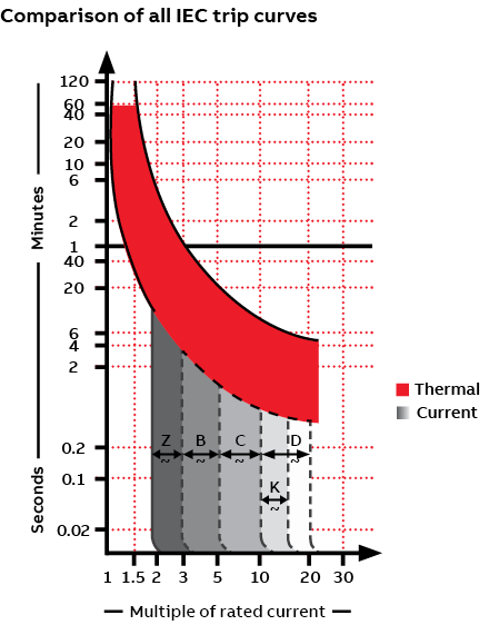
Referring back to the “Comparison of all IEC trip curves” graph, you can see that higher currents trigger more rapid trips.
The ability to tolerate inrush current is an important consideration in trip-curve selection. Certain loads, notably motors and transformers, experience a momentary change in current, the inrush current, at contact closure. Faster protective devices, like a B-trip curve, would see this inrush as a fault and open the circuit. For these types of loads, trip curves with a higher magnetic tripping point, either D or K, can “ride through” the momentary inrush of current, protecting the circuit without nuisance tripping.
Choosing the right trip curve The availability of a range of trip curves and options for different current levels within each range enables selection of an appropriate breaker to protect a variety of loads in various applications.
With large, molded case circuit breakers , you can select one of a number of breakers and then adapt it to the application by adjusting its operating parameters. The same isn’t true for miniature circuit breakers. Their operating parameters are fixed, making it critical that you select the breaker to meet the required specs, including the appropriate trip curve for the application.
Armed with the operating values for a circuit or application/load, it’s possible to make a good selection of the appropriate trip curve. However, this may require some trial and error to arrive at the optimum breaker. Recurring nuisance tripping may be a sign an alternate may be a better fit.
To help ensure the optimal balance between protection and minimal nuisance tripping, the best approach may be to consult with the device manufacturer or distributor. Provide them with the details of your application, and they should be able to recommend the right miniature circuit breakers to meet your needs.
— Thomas Weinmann Senior Product Marketing Manager
ABB Electrification Business
Presented by:
This site is created by ABB application engineers and experts as an educational tool to help engineers.

IMAGES
VIDEO
COMMENTS
A circuit breaker has two types of tripping unit i.e. thermal and magnetic tripping unit. Thermal Tripping Unit: the thermal tripping unit is used for protection against overloading. It uses a bi-metallic contact that bends with a change in temperature. The current flowing through the bimetallic strip heats up contact & trip the circuit breaker.
All Support & Contact. Find answers now. Search for a solution on your own, or connect with one of our experts. Schneider Electric USA. Quick links to pre-filtered listings of tripping curves available in our download center.
The trip curve of an MCB (B, C, D, K, and Z curves) tells us about the trip current rating of Miniature Circuit breakers. The trip current rating is the minimum current at which the MCB will trip instantaneously. It is required that the trip current must persist for 0.1s. Table of contents. Definition.
Understanding Circuit breaker tripping Curves. Circuit breakers are essential components in electrical systems as they protect the circuits from overloads and short circuits. One important characteristic of circuit breakers is their tripping curve, which determines the response time and sensitivity of the breaker to different levels of fault currents.
circuit breaker will override all settings and will trip instantaneously. 14 - INSTANTANEOUS PICKUP SETTING: the nominal value of current that an adjustable circuit breaker is set to trip instantaneously. 15 - INSTANTANEOUS TRIP: a qualifying term indicating that no delay is pur-posely introduced in the automatic tripping of the circuit breaker.
Altech discusses Circuit Breaker Trip Curves.
This portion of the curve is said to have an inverse time characteristic, which means that the CB will trip in less time at higher levels of current flow. Typical time-current characteristic curve for a 3P, 600A frame size molded-case circuit breaker in open air at rated temperature, usually 40 degrees Celsius.
3. Consider system coordination: In a system with multiple circuit breakers, it is essential to ensure they coordinate correctly. For example, electrical control panel builders should select the trip curves to provide the downstream circuit breaker trips before the upstream breaker.
Every circuit breaker has a characteristic curve that reports the manner in which it trips. As this curve is reporting the amount of current vs time, it is a...
Trip curves may be called tripping characteristics, current curve, current-time curve or other terms. A trip curve is simply a description of how an overcurrent based on time will trip a fuse or circuit breaker. For this video we'll focus on breakers but the same applies to fuses. You may see breakers sold based on trip curve. Looking at the ...
Power Break II Insulated Case Circuit Breaker; Types SS, SH with Power +, MicroVersaTrip Plus or MicroVersaTrip PM; Long-time, Short-time and Instantaneous ... (RELT) Trip Curves. DES-091A. EntelliGuard G & R: Long-Time Trip Curve (Fuse/ I^4t) DES-090A. EntelliGuard G & R: Long-Time Trip Curve (Thermal/ I^2t) DES-092B ... Residential Circuit ...
quickest the circuit breaker will trip is forty seconds (1). Forty seconds at 2X the rated current is the slowest the circuit breaker will trip (2). The bottom of the chart is for the magnetic trip of the coil/solenoid; 0.02 to 2.5 seconds at 3X the rated current is the soonest the circuit breaker will trip (3).
Learn the basics of circuit breaker trip curves by understanding what they are and how we use them.Get the FULL video transcript here: https://www.rspsupply....
Miniature Circuit Breaker (MCB) Trip calculation. First, look for the amperage marking on the switch of the MCB. This is usually between 15 or 20. Also look for the voltage marking on the breaker switch, this will be between 120 or 240. Second, locating the voltage and current rating, multiply the volts and the amps.
6. The end of the curve is determined by the interrupting rating of the circuit breaker. 7. SHORT TIME: FLAT only Tolerance is +0/ -80 ms of setting except 0.10s setting is 0.06 to 0.13 0.15s setting is 0.10 to 0.17 0.20s setting is 0.15 to 0.22 8. Curve applies from -20°C to +55°C ambient. Temperatures above +85°C cause automatic trip. 9.
Trip curves in circuit breakers represent the relationship between the magnitude of the fault current and the time it takes for the circuit breaker to trip. These curves help determine the response of the circuit breaker to different levels of fault currents. The trip curves are typically categorized into different classes, such as B, C, D, K ...
the trip curve has no counterpart on the UL side. Trip curve origins The concept of trip curves originated in the IEC world. The alphabetic code used to categorize miniature circuit breakers (B, C, D, K, and Z) carried over from IEC standards. The standard defines the lower and upper thresholds for tripping, but manufacturers have
Series C F-frame circuit breaker time current curves. Contents (continued) Two-, three-, and four-pole thermal-magnetic trip units Page ... It is not to be used to build catalog numbers for circuit breakers or trip units . 5 Time Current Curves TC01200002E Effective April 2022 Series C F-Frame EATON www.eaton.com Figure 2. Digitrip 210+ Nameplates
https://www.AutomationDirect.com/circuit-protection - (VID-CP-0009) Circuit breaker and fuse trip curves (CB Trip curves) explain how a trip occurs based on ...
The numbers you want are the ampacities of the breaker they should trip close to this value. the normal load for a breaker is 80% of the value on the handle. As breakers age or have been tripped many times sometimes they do trip early. If you need the curve values we need the type and brand. The type is normally something like "QP".
MCB or Miniature Circuit Breaker is an electromechanical device that protects an electric circuit from an overcurrent. The overcurrent in an electrical circuit may result from short circuit, overload or faulty design.. This article explains different MCB types, their working and trip curves. In short, MCB is a device for overload and short circuit protection.
Trip Curves TC003002EN Effective April 2016 Type BR thermal magnetic trip curve results EAT www.eaton.com Figure 6. Types QFP, VQFP - 125-225 Amperes, 2 and 3 Poles. Circuit Breaker Time/Current Curves For application and coordination purposes only. Based on 40°C ambient, cold start. Connected with four (4 feet of rated wire (75°C per terminal.
Trip curves are defined by IEC standards 60898-1 and 60947-2. The curves actually represent two different trip functions within the miniature circuit breaker - thermal and electro-magnetic. The thermal section (top section of the chart) that responds to overloads typically consists of a bi-metallic strip. The response of the thermal trip unit ...