
Travelling Wave Tube (TWT)
A travelling wave tube is a high power amplifier used for the amplification of microwave signals up to a wide range. It is a special type of vacuum tube that offers an operating frequency ranging between 300 MHz to 50 GHz .
Travelling wave tubes are non-resonant structures that offer continuous interaction of applied RF field with the electron beam over the entire length of the tube. Due to this reason, it provides wider operating bandwidth.
Content: Travelling Wave Tube
Basic concept.
- Construction
Need of Slow-Wave Structure
- Applications
Travelling wave tubes are abbreviated as TWT . It is majorly used in the amplification of RF signals. Basically a travelling wave tube is nothing but an elongated vacuum tube that allows the movement of electron beam inside it by the action of applied RF input.
The movement of an electron inside the tube permits the amplification of applied RF input. As it offers amplification to a wide range of frequency thus is considered more advantageous for microwave applications than other tubes.
It offers average power gain of around 60 dB . The output power lies in the range of few watts to several megawatts.
A travelling wave tube is basically of two types one is helix type and the other is coupled cavity. Here in this section, we will discuss the detailed construction and working of a helical travelling wave tube.
Construction of Travelling Wave Tube
The figure here shows the constructional structure of a TWT:

As we can see that the helical travelling wave tube consists of an electron gun and a slow-wave structure . The electron gun produces a narrow beam of the electron. A focusing plate is used that focuses the electron beam inside the tube.
A positive potential is provided to the coil (helix) with respect to the cathode terminal. While the collector is more positive than the coil (helix). In order to restrict beam spreading inside the tube. A dc magnetic field is applied between the travelling path by the help of magnets.
The signal which is needed to be amplified is provided at one of the ends of the helix, present adjacent to the electron gun. While the amplified signal is achieved at the opposite end of the helix.
In the figure, we can clearly see that attenuator is present along both the sides of the travelling wave tube. This is so because travelling wave amplifiers are high gain devices, so in case of poor load matching conditions, oscillations get build up inside the tube due to reflection.
Thus in order to restrict the generation of oscillations inside the tube attenuators are used.
Attenuators are basically formed by providing a metallic coating over the surface of the glass tube. Aquadag or Kanthal are majorly used for this.
It is to be noteworthy that a slow-wave structure is considered here, the reason is to maintain continuous interaction between the travelling wave and electron beam.
We know that the velocity of the electromagnetic wave is very much higher when compared with the phase velocity of the electron beam emitted by the electron gun.
Basically the RF wave applied at the input of TWT propagates with the speed of light (i.e., 3 * 10 8 m/s ). While the propagating velocity of the electron beam inside the tube is comparatively smaller than the velocity of RF wave.
If we try to somehow accelerate the velocity of the electron beam, then it can be accelerated only to a fraction of velocity of light. So it is better to reduce the velocity of the applied RF input in order to match the velocity of the electron beam.
Therefore, a slow-wave structure is used that causes a reduction in the phase velocity of the RF wave inside the TWT.
The slow-wave structures can be of different types like a single helix, double helix, zigzag line, corrugated, coupled-cavity or ring bar type etc.
A single helix slow-wave structure is formed by wounding a wire of element like tungsten and molybdenum in the form of a coil. The helical shape of the structure slows the velocity of the wave travelling along its axis to a fraction of about one-tenth of c.
This is so because due to the helical shape of the structure, the wave travels a much larger distance than the distance travelled by the beam inside the tube. So, in this way, the speed of wave propagation depends on the number of turns or diameter of the turns.
More specifically we can say that change in pitch can vary the speed of wave propagation inside the tube.
The equation given below shows the relation of phase velocity of the wave with the pitch of the helix:

: c = velocity of light (3 * 10 8 m/s)
V P = phase velocity in m/s
P = pitch of helix in m
d = diameter of the helix in m
Therefore, this causes continuous interaction between the RF input wave and the electron beam as the velocity of propagation of the two is not highly different. As such interaction is the basis of working of TWT thus slow-wave structures are used.
Working of Travelling Wave Tube
Till now we have discussed the complete constructional structure of TWT. Let us now understand how the signal gets amplified while travelling inside the tube.
The applied RF signal produces an electric field inside the tube. Due to the applied positive half, the moving electron beam experiences accelerative force. However, the negative half of the input applies a de-accelerative force on the moving electrons.
This is said to be velocity modulation because the electrons of the beam are experiencing different velocity inside the tube.
However, the slowly travelling wave inside the tube exhibits continuous interaction with the electron beam.
Due to the continuous interaction, the electrons moving with high velocity transfer their energy to the wave inside the tube and thus slow down. So with the rise in the amplitude of the wave, the velocity of electrons reduces and this causes bunching of electrons inside the tube.
The growing amplitude of the wave resultantly causes more bunching of electrons while reaching the end from the beginning. Thereby causing further amplification of the RF wave inside the tube.
More specifically we can say that forward progression of the field along the axis of the tube gives rise to amplification of the RF wave. Thus at the end of the tube an amplified signal is achieved.
The positive potential provided at the other end causes collection of electron bunch at the collector.
The magnetic field inside the tube restricts the spreading of the beam as the electrons possess repulsive nature.
However, as the TWT is a bidirectional device . Therefore, the reflected signal causes oscillations inside the tube. But as we have already discussed earlier that the presence of attenuators reduces the generation of oscillations due to reflected backwave.
Sometimes despite using attenuators, internal impedance terminals are used that puts less lossy effects on the forward signal.
Applications of TWT
- Travelling wave tubes are highly used in continuous wave radar systems.
- These amplifying tubes also find application in broadband receivers for RF amplification.
- TWT’s are also used to get high power output in satellite transponders.
So from the above discussion, we can conclude that no resonant structure is present in the interaction space. Thus provides amplification up to a wide bandwidth operating range.
However, the input and output coupling arrangements must be considered carefully as they limit the operating range.
Related Terms:
- Transmission Lines
- IMPATT Diode
- Backward Wave Oscillator
Leave a Comment Cancel Reply
Your email address will not be published. Required fields are marked *
Traveling Wave Tubes
Traveling Wave Tubes are vacuum-based devices that amplify microwave signals with high gain and wide bandwidth, used in radar, communication, and satellites.

Traveling Wave Tubes: A Comprehensive Introduction
What are traveling wave tubes.
Traveling Wave Tubes (TWTs) are specialized vacuum tubes that are commonly used as high-power, wideband, and linear amplifiers for microwave frequency signals. Invented by Rudolf Kompfner in 1943, TWTs have since become an essential component in radar, communication systems, and satellite technology, enabling the transmission of signals over long distances with minimal loss and distortion.
How do Traveling Wave Tubes work?
At the core of a TWT is a helix, a coiled wire that acts as a slow-wave structure. The helix is housed in an electron beam-controlling cylindrical tube, which is encased within a vacuum. The electron beam is generated by an electron gun, and its velocity is controlled by an external magnetic field.
When a microwave signal enters the TWT, it travels along the helix, interacting with the electron beam. The electrons, which move at a similar velocity to the microwave signal, transfer energy to the signal, amplifying it. As the microwave signal continues to travel along the helix, it accumulates energy, resulting in significant amplification by the time it exits the TWT.
Key Components of a Traveling Wave Tube
- Electron Gun: Generates the electron beam that interacts with the microwave signal to amplify it.
- Helix: A slow-wave structure that enables the interaction between the microwave signal and the electron beam. The helix is critical to the performance of a TWT, as it determines the frequency range and gain of the device.
- Collector: Captures the spent electron beam after it has transferred its energy to the microwave signal. The collector converts the remaining kinetic energy of the electrons into heat, which is then dissipated by a cooling system.
- Magnetic Field: An external magnetic field is used to control the velocity and trajectory of the electron beam, ensuring that it remains focused and properly aligned with the helix.
- Vacuum Tube: The TWT operates within a vacuum to minimize energy loss due to interactions with air molecules and to prevent the formation of plasma, which could damage the device.
Advantages of Traveling Wave Tubes
Traveling Wave Tubes offer several advantages over other microwave amplification technologies, such as solid-state amplifiers and klystrons. Some of the key benefits include:
- Wide Frequency Range: TWTs can operate over a broad range of frequencies, typically from 0.3 GHz to 50 GHz or higher. This makes them suitable for a wide variety of applications, from radar systems to satellite communications.
- High Gain: TWTs can achieve high gain, often in the range of 40 to 60 dB or more, enabling the amplification of weak signals for transmission over long distances.
- Wide Bandwidth: The bandwidth of a TWT can be several gigahertz, allowing for the simultaneous amplification of multiple signals or channels.
Disadvantages of Traveling Wave Tubes
Despite their numerous advantages, TWTs also have some drawbacks that must be considered when selecting an appropriate microwave amplifier for a specific application. These include:
- Complexity and Cost: TWTs are complex devices with many components, making them more expensive to manufacture and maintain compared to some solid-state amplifiers.
- Size and Weight: The vacuum tube and cooling systems required for TWTs can result in larger and heavier devices, which may not be suitable for all applications, especially in space-constrained environments.
- Lower Efficiency: TWTs tend to have lower power efficiency compared to solid-state amplifiers, which can lead to higher power consumption and increased cooling requirements.
Applications of Traveling Wave Tubes
Traveling Wave Tubes have been widely adopted in various industries and applications due to their unique capabilities. Some of the most common uses for TWTs include:
- Radar Systems: TWTs are used in radar systems for both military and civilian purposes, providing high-power amplification for signals used in air traffic control, weather forecasting, and defense applications.
- Communications: TWTs play a crucial role in satellite communications, enabling the transmission of signals over long distances with minimal loss and distortion. They are also used in terrestrial microwave communication links and undersea cable systems.
- Electronic Warfare: TWTs are employed in electronic warfare systems, such as electronic countermeasures (ECM) and electronic support measures (ESM), to amplify signals for jamming or intercepting enemy communications and radar signals.
- Particle Accelerators: TWTs are utilized in some particle accelerator facilities to provide high-power microwave signals required for accelerating charged particles to high velocities.
Future of Traveling Wave Tubes
Despite the ongoing development and adoption of solid-state amplifiers, TWTs continue to be relevant in many applications due to their unique capabilities. Research efforts are being directed towards improving the efficiency, size, and weight of TWTs to enhance their competitiveness with solid-state technologies.
One promising area of research involves the development of new materials and manufacturing techniques for TWT components, such as advanced helix structures and electron guns. These innovations could result in significant performance improvements, making TWTs even more attractive for a wide range of applications.
Traveling Wave Tubes remain an essential technology for amplifying microwave signals in a variety of industries and applications, from radar systems to satellite communications. Their wide frequency range, high gain, and wide bandwidth make them indispensable for many critical systems. Although solid-state amplifiers have gained traction in recent years, ongoing research and development in TWT technology ensure that they will continue to play a vital role in the future of microwave signal amplification.
Related Posts:

The primary purpose of this project is to help the public to learn some exciting and important information about electricity and magnetism.
Privacy Policy
Our Website follows all legal requirements to protect your privacy. Visit our Privacy Policy page.
The Cookies Statement is part of our Privacy Policy.
Editorial note
The information contained on this website is for general information purposes only. This website does not use any proprietary data. Visit our Editorial note.
Copyright Notice
It’s simple:
1) You may use almost everything for non-commercial and educational use.
2) You may not distribute or commercially exploit the content, especially on another website.
Accessibility Links
- Skip to content
- Skip to search IOPscience
- Skip to Journals list
- Accessibility help
- Accessibility Help
Click here to close this panel.
Purpose-led Publishing is a coalition of three not-for-profit publishers in the field of physical sciences: AIP Publishing, the American Physical Society and IOP Publishing.
Together, as publishers that will always put purpose above profit, we have defined a set of industry standards that underpin high-quality, ethical scholarly communications.
We are proudly declaring that science is our only shareholder.
Recent theory of traveling-wave tubes: a tutorial-review
Patrick Wong 1 , Peng Zhang 1 and John Luginsland 2
Published 3 June 2020 • © 2020 IOP Publishing Ltd Plasma Research Express , Volume 2 , Number 2 Citation Patrick Wong et al 2020 Plasma Res. Express 2 023001 DOI 10.1088/2516-1067/ab9730
Article metrics
4267 Total downloads
Permissions
Get permission to re-use this article
Share this article
Author e-mails.
Author affiliations
1 Department of Electrical and Computer Engineering, Michigan State University, East Lansing, MI 48824, United States of America
2 Confluent Sciences, LLC, Albuquerque, NM 87111, United States of America
Patrick Wong https://orcid.org/0000-0002-8437-6990
Peng Zhang https://orcid.org/0000-0003-0606-6855
John Luginsland https://orcid.org/0000-0002-6130-6156
- Received 3 March 2020
- Revised 8 April 2020
- Accepted 27 May 2020
- Published 3 June 2020
Peer review information
Method : Single-anonymous Revisions: 1 Screened for originality? Yes
Buy this article in print
The traveling-wave tube (TWT), also known as the traveling-wave amplifier (TWA) or traveling-wave tube amplifier (TWTA), is a widely used amplifier in satellite communications and radar. An electromagnetic signal is inputted on one end of the device and is amplified over a distance until it is extracted downstream at the output. The physics behind this spatial amplification of an electromagnetic wave is predicated on the interaction of a linear DC electron beam with the surrounding circuit structure. Pierce, known as the 'father of communications satellites,' was the first to formulate the theory for this beam-circuit interaction, the basis of which has since been used to model other vacuum electronic devices such as free-electron lasers, gyrotrons, and Smith-Purcell radiators, just to name a few. In this paper, the traditional Pierce theory will first be briefly reviewed ; the classic Pierce theory will then be extended in several directions: harmonic generation and the effect of high beam current on both the beam mode and circuit mode as well as 'discrete effects', giving a brief tutorial of recent theories of TWTs.
Export citation and abstract BibTeX RIS
This article was updated on 22 April 2021 to add permission lines to the figures.
Introduction
Throughout the history of commercial and defense applications involving electromagnetics, there has always been a high demand for microwave and millimeter wave amplifiers that offer both high power output and wide bandwidth. One candidate that may fulfill these stringent requirements is the traveling-wave tube (TWT), also known as the traveling-wave amplifier (TWA) or traveling-wave tube amplifier (TWTA). This device is widely used in satellite communications and radar applications.
It turns out that a viable method of amplifying a given electromagnetic wave is by passing this signal through a periodic structure and co-propagating it with a linear DC electron beam. To reduce complexities, this beam-circuit interaction takes place in vacuum. In such a set-up, the traveling wave gains energy at the expense of the kinetic energy of the electron beam. This continuous interaction and subsequent amplification of the electromagnetic wave happens over a distance (the length of the interaction region of the TWT) until the amplified wave is extracted at the output.
Before the invention of the TWT, the klystron amplifier (1935) was one of the first microwave amplifiers used [ 1 – 4 ]. This device though had several limitations. The most notable one is that the klystron had narrow bandwidth, as amplification is restricted to the resonant frequencies of the klystron cavities. The idea then came about to couple the individual cavities of a multi-cavity klystron to a common transmission line so that there may be a continuous in-phase interaction between beam and circuit [ 3 , 4 ]. This eventually led to the development of the traveling-wave tube amplifier. Figure 1 shows the evolution of the klystron to the traveling-wave tube.

Figure 1. Schematic diagram showing the evolution of a multi-cavity klystron (a) to a traveling-wave tube amplifier (c). (b) shows the multi-cavity klystron with its cavities coupled to a common transmission line.
Download figure:
Rudolph Kompfner of England, interestingly an architect by profession, was the first to propose the idea of a traveling-wave tube. He and Nils Lindenblad of the United States used a metallic helix as the circuit structure for propagating the signal in phase with the centered pencil electron beam in vacuum and are credited with being the first to create the TWT as it is known today [ 5 , 6 ]. Prior to this, Haeff proposed a similar idea but had the electron beam on the outside of the circuit, leading to poorer efficiency [ 7 ]. Kompfner's invention of the TWT then aroused the intense interest of John R Pierce who then laid the foundation of the TWT theory and was later known as the 'father of communications satellites' [ 8 ]. A schematic diagram of a modern TWT is shown in figure 2 .

Figure 2. Schematic diagram of a traveling-wave tube amplifier. There are many components to a TWTA. In this paper, we will concentrate only on the middle section, the helix, of the above figure: the beam-circuit interaction region. The slow-wave circuit shown here is a helix (with support rods). Image from [ 9 ]. This diagram of helix TWT has been obtained by the author(s) from the Wikipedia website, where it is stated to have been released into the public domain. It is included within this article on that basis.
As can be seen in figure 2 , an actual TWT is a complex device, consisting of components (left: cathode, electron gun, etc) that create and form the electron beam, the beam-circuit interaction region (middle: helix, electron beam, etc), and components (right: collector) that collect the 'spent' beam. Each of these topics in and of themselves constitute a library of study. In this paper, the focus will be restricted to the physics in the beam-circuit interaction region within the helix (figure 2 ). In particular, the standard beam-circuit mode coupling theory of Pierce will be examined. Using the Pierce theory as a basis, we will then extend it to describe effects originally neglected by Pierce: harmonic generation and the effects of high beam current on the circuit as well as connecting the continuous wave picture of Pierce to a discrete circuit formulation.
To begin, it must be emphasized that the operation of a TWT, or virtually any beam-driven microwave source, is predicated on the interaction of an electron beam in vacuum with an in-phase, co-propagating electromagnetic wave on a circuit structure. As such, it is instructive to analyze each of these two components: beam and circuit separately and then describe their interaction, as was also done by Pierce [ 10 ]. This method of analysis and mode coupling is not restricted to TWTs, rather, the techniques presented here are quite general and applicable to all beam-circuit interactions between charged particles and electromagnetic radiation.
The electron beam
As can be seen in figure 2 , the electron beam is formed outside of the beam-circuit interaction region. Electrons are boiled off from a thermionic cathode (thermionic emission) or emitted from a material using strong electric fields (field emission). In either scenario, a voltage is externally applied to the cathode and this is essentially the kinetic energy of the beam entering the interaction region. We will denote the kinetic energy of this beam by voltage V b , corresponding to a DC beam velocity v 0 . Invoking conservation of energy in the non-relativistic regime,
For simplicity, it is assumed that there are no temperature effects on the beam so that the beam is 'cold' or mono-energetic (introducing temperature effects will be slightly more complicated but will essentially introduce a spread in electron velocities centered around a mean value). We further assume that the DC beam motion is one-dimensional, i.e., we implicitly assume that there is an infinite axial magnetic field confining the beam. In reality, this is provided by an external solenoid or periodic permanent magnets.
The two externally adjustable parameters of the beam: the DC beam voltage V b and the DC beam current I 0 control the unperturbed electron beam velocity v 0 and the electron charge density ρ 0 , respectively. In the absence of any perturbation, the electron beam travels through vacuum in the axial direction with these unperturbed properties.
The electromagnetic circuit
There are of course other SWS designs for different purposes. A listing and description of some of these SWS designs can be found in [ 11 ]. Traditionally speaking, all of the structures are metallic, but much effort has, in recent years, been placed in studying metamaterial SWS's [ 12 , 13 ]. These have very different dispersion characteristics than their metallic counterparts leading to different gain properties. However, their beam-circuit interaction may still be captured by the mode-coupling theory of Pierce (in the small-signal regime); the physics and mathematics of the beam and circuit coupling remains the same. Different beam configurations (e.g. pencil beam versus sheet beam versus annular beam) will also play a role in the gain characteristics of the tube (see [11a] for a comparison between pencil and annular beams and [11b] for a discussion comparing sheet beams, an 'unwrap' of annular beams, to pencil beams; [ 14 ] talks about the plasma frequency reduction factor for different beam configurations, a topic we will come back to soon). Still to this date though, the helix SWS coupled with a pencil electron beam remains the 'go-to' for high power microwave amplification because of its wide bandwidth and ease of construction.
The reason why a helix TWT may offer a wide bandwidth is qualitatively illustrated in figure 3 .

Figure 3. (a) Depiction of the TEM fields of a thin wire over a perfectly conducting metal plate. (b) The formation of a helix TWT from 'wrapping' the set-up in (a).
where E C is the circuit electric field, Γ 0 is the effective propagation constant of this circuit wave (= β ph with an imaginary part to account for attenuation in the circuit), and K is known as the interaction impedance (essentially a pure geometrical quantity that is a proportionality constant between the voltage and current of the 'cold' no beam system). Assuming time and spatial harmonic fields, equation ( 3 ) may be written as:
β 0 (or just β in the literature) is called the fundamental, and β n ( n ≠ 0) is called the n th space harmonic.

What we have allured to but have neglected to discuss thus far is the space-charge electric field E SC coming from the beam, with good reason. Space-charge calculations in general are notoriously difficult, and there is no general model that can capture this internal self-force of the beam. It turns out, see the section 'Beyond Pierce', that one model of space-charge effects is intimately tied to the higher-order passbands of the circuit and the higher-order beam modes. This higher-order interaction was not initially captured by Pierce as his analysis was concerned with the interaction of the fundamental passband and beam mode only. It should be noted though that he did hypothesize the role of higher-order passbands of the circuit on space charge; for now, we will group space-charge effects under the term 'QC' or 'Q', following Pierce's original notation. Thus, accessing space-charge effects in TWTs boils down to finding an expression for 'Q', known as Pierce's AC space-charge parameter.
The Beam-Circuit Interaction and Pierce's theory of mode-coupling
Now that we have described the beam and circuit separately, how do they interact in such a way to produce amplification of the injected signal? When the beam enters the beam-circuit interaction region and feels the circuit wave, the electrons in the beam will respond to the sinusoidal nature of the electric field of the signal. Consequently, one can imagine that some electrons will be accelerated by the accelerating portion of the wave and some electrons will be decelerated by the decelerating portion of the wave. This leads to the formation of electron bunches in the electron beam. These bunches in turn cause the electric field in the circuit to increase by inducing more current in the circuit; electron motion inducing currents in external circuits can be attributed to the famous Shockley-Ramo Theorem [ 20 ]. The resulting amplitude increase in the electric field in the circuit causes more bunching in the beam. The physical mechanism is succinctly illustrated in Gilmour's book [ 1 , 2 ].
From a wave mechanics picture, a pair of space-charge waves on the electron beam are created from the beam interacting with the circuit wave. These space-charge waves on the beam are analogous to longitudinal pressure waves in air consisting of compressions and rarefactions. In this case, we have the fast and slow space-charge waves that co-propagate on the electron beam with the circuit wave. The energy difference from the slowing-down of the electrons in the beam to the slow space-charge wave phase velocity is given to the circuit, causing amplification of the circuit wave. This beam-circuit interaction has proven to be effective: the growth of the input signal, at least in the small-signal regime, is exponential with distance along the tube [ 1 , 2 ]. TWT power gain of 60 dB (1 million times) can be realized [ 21 ].
As stated before, the classical theory of beam-structure interactions in a TWT was developed by Pierce [ 10 ], whose treatment also provided the foundations for the understanding and design of a wide range of contemporary sources such as free-electron lasers [ 4 , 22 – 24 ], Smith-Purcell radiators [ 4 , 23 – 26 ], gyrotron amplifiers [ 4 , 26 – 30 ], metamaterials TWTs [ 12 , 13 , 31 ], and NonLinear Transmission Line (NLTL) based sources [ 32 ]. We will present the standard Pierce theory and further develop it to indicate other novel effects not previously considered by Pierce. Pierce described the energy transfer mechanism in terms of the interaction between the space-charge waves on the electron beam and the electromagnetic mode supported by the electromagnetic circuit. Amplification of a signal of frequency ω is described by the complex wavenumber β that is a solution of what is known as the Pierce dispersion relation, which, in its most basic form [ 1 , 3 , 4 , 10 , 13 , 22 – 24 , 26 – 30 ], is a third-degree polynomial for β(ω) . This dispersion relation describes the coupling between the beam mode and the circuit mode [ 33 , 34 ]. It has been used in the validation of non-linear, large-signal numerical codes in the small-signal regime.
An interesting side note is that unlike most topics, such as plasma physics and electromagnetic wave theory, here we consider the propagation constant as a function of the frequency. That is, one is generally given a frequency (the frequency of the input signal to be amplified) and is tasked with finding the corresponding propagation constant, which is in general complex. The imaginary part corresponds to either the growth (amplification) or decay (attenuation) of the wave in the system.
We are now in a position to self-consistently solve the governing equations for the beam (equations ( 1 ), ( 2 )) and circuit (equation ( 3 )) to yield solutions describing the evolution of both, as a coupled system. With some manipulation, the three equations can be combined to yield:
To simplify matters (this was back in the day when solving quartic polynomials was a chore!), a common approximation is to assume that C is small and to neglect the backward circuit wave, as it is primarily the forward waves that contribute to the gain of a TWT downstream. Doing so and using the notation of Pierce, the so-called 3-wave dispersion relation reads:
For comparison purposes (c.f. equation ( 5 ') below), Pierce's 3-wave dispersion relation for β reads:
It should be noted that reflection from the ends and waves near the band edges cannot be accounted for by Pierce's 3-wave theory. A classical look into Pierce's 4-wave theory and its reduction to the 3-wave theory is provided by Birdsall and Brewer [ 35 ]. The importance of the 4-wave description, and the effects of reflection on the TWT stability may be found in [ 36 – 38 ].
Beyond pierce
The above was a tour-de-force through electron beam dynamics and electromagnetic wave theory culminating in a simple yet powerful description of beam-circuit mode coupling and interaction in a TWT. One must remember that this type of analysis was done back in the early to mid-20th century. Many advancements in terms of modeling and mathematics and the advent of scientific supercomputing have taken analyses of such devices to new heights. Consequently, more complex and accurate descriptions on the inner workings of a TWT exist. Nevertheless, there is still a subtle charm to a simple theory. Not only can it give a 'back-of-the-envelope' assessment of a given problem but it can provide great physical insights into the nature of such interactions and processes. In this vein, we will now attempt to relax some of the assumptions of Pierce and extend his theory in a simple manner and draw further insights into the beam-circuit interaction. The topics covered here will be harmonic generation and space charge in TWTs as well as 'discrete cavity' effects, relating TWT analysis to klystron analysis. A brief synopsis of the first two topics are provided in the following paragraphs.
The classical Pierce theory was formulated for a single (fundamental) frequency, that of the input signal. However, in a TWT with an octave bandwidth or greater, in particular the widely used helix TWT, the second harmonic of the input signal may also be within the amplification band and thus may also be generated and amplified, with no input at this second harmonic frequency. An extension to the Pierce formulation that incorporates the generation of harmonics will be presented here. It is shown that the second harmonic arises mostly from a newly discovered dynamic synchronous interaction instead of by the kinematic orbital crowding mechanism that is the most dominant harmonic generation mechanism in other microwave devices. The methodology provided here, which is a natural extension of Pierce's original theory, may be applicable not only to TWTs but to other high-power microwave sources.
In beam-circuit interactions, the space-charge effect of the beam is important at high beam currents. In Pierce's TWT theory, as stated before, this space-charge effect is modelled by the parameter which he called Q in the beam mode. A reliable determination of Q remains elusive for a realistic TWT. Previously, Wong et al [ 39 ] constructed the first exact small-signal theory for the beam-circuit interaction for the tape helix TWT, from which Q may be unambiguously determined. In the process of doing so, it was discovered that the circuit mode in Pierce's theory must also be modified at high beam current, an aspect overlooked in Pierce's original analysis. This circuit mode modification is quantified by an entirely new parameter called q , introduced for the first time in TWT theory. For the example using a realistic tape helix TWT, we find that the effect of q is equivalent to a modification of the circuit phase velocity by as much as two percent, which is a very significant effect. A brief summary of q will be provided here.
Harmonic generation in TWTs
The subject of harmonic generation in a TWT has traditionally been studied in the non-linear, large-signal regime. We will not delve into large-signal theory here as it is beyond the scope of this text. The theory itself is more complete as it can not only capture non-linear phenomena such as saturation, wave-trapping of beam electrons, etc. but can also recover the linear, small-signal regime. However, it is much more complicated than the relatively simple linear theory presented here thus far and simple insights, which we stress here, cannot be easily drawn. We will note here that large-signal TWT theory and also the study of harmonics of the input signal can be traced back to the classical paper by Nordsieck [ 40 ], who also provided the first analysis of TWT efficiency. References may be made to Tien et al , Rowe, Giarola, and Dionne [ 41 ] whose subsequent works relied heavily on Nordsieck's initial theory.
Taking a step back, it is well-known in klystrons that the dominant cause of harmonics of the input signal to be generated is due to linearized orbital motion from an input signal leading to orbital crowding, which leads to harmonic generation kinematically [ 3 , 42 ] (see figure 5 below). In such scenarios, the extreme case of charge overtaking may also occur and contribute to harmonic generation. It was not until recently that such a theory on harmonic content in the beam current of a TWT was developed by Dong et al [ 43 ] in the small-signal regime. In that work, the linearized electron orbits might lead to a second harmonic AC current as high as 25% of the DC beam current, and this was favorably compared to the large-signal TWT code CHRISTINE [ 44 ].

Figure 5. An (exaggerated) illustration of harmonic generation due to orbital crowding. Crowding in the linear orbits may lead to harmonic current generation, as shown in klystron theory [ 3 ] and TWT theory [ 43 ].
A little after Dong et al 's paper, another source of harmonic content in a TWT was discovered: weak non-linearities in the electron orbits. It turns out, with respect to the RF power output, that this source of harmonic generation is much more important as it possesses the property of synchronism between the beam and circuit in both space and time , the underpinning concept behind the operation of TWTs. The effect of orbital crowding described in the preceding paragraph is negligible in comparison [ 45 ].
The main idea behind this alternative view on harmonic generation in TWTs stems from carrying out higher-order expansions of the governing equations for the beam [recall: Pierce's small-signal analysis is a linear theory; this is the answer to the above question posed in Footnote 1]. These minor corrections on the quantities of the beam corrects the linear quantities of Pierce [ 46 ] but also turn out to be the harmonics; basically, we regard the quantities of interest: the electric field (potential), beam density and velocity (current) to be represented by a Fourier series. This interpretation then is a quasi-linear theory.
The electromagnetic signal causes the electrons in the beam to bunch. To first order, these bunches are at the frequency of the signal itself, leading to Pierce's linear theory. The orbits of the beam electrons though are better represented at higher orders and thus contain more frequencies of the input signal. In response, the circuit picks up each of these frequencies individually (Maxwell's Equations are linear). The circuit then not only supports an amplifying signal at the fundamental (input) frequency but also a spectrum of harmonics of the original signal, all being spatially amplified. This of course can only happen if the spectrum of frequencies is within the bandwidth of the TWT: any frequency outside of the characteristic bandwidth will not be supported by the structure. The ubiquitous helix structure is one such circuit structure that can have octave bandwidth, as evidenced by figure 4 above.
Space-charge effects in TWTS
Let us now go back to the notorious problem of space-charge effects, or finding a closed form expression for Q in the Pierce picture. Many theories have been proposed that attempt to give a general formulation for calculating Q for a general beam and circuit structure. A treatise of the subtlety of this problem is given by Lau and Chernin [ 49 ], who ultimately advance the idea that Q is due to the interaction of the beam with the higher-order circuit modes (passbands higher than the fundamental). This interpretation of Q originating from residual interactions between beam and circuit, the 'remainder,' was actually also proposed by Pierce [ 10 ], who quickly abandoned such an interpretation [ 49 ], adhering instead to what the standard Pierce theory is now: the interaction between the fundamental circuit and beam modes.
Physically speaking, the calculation of the space-charge parameter boils down to calculating the 'reduced' plasma frequency ω q of the beam. Like a plasma, the beam, which can be considered to be a non-neutral plasma, has a natural frequency called the electron beam plasma frequency, which is the frequency of the space-charge waves in an unbounded medium. However, in reality, the beam is bounded in the sense that it has a definite shape and is enclosed by the finite circuit structure. Thus, the plasma frequency of the beam is 'reduced'. In this view, the task is to calculate the reduction factor to the plasma frequency that accounts for the circuit structure (including the SWS, taking into account, for example, the 'field leakage' in the opened sections of a helix). It turns out that this calculation is intimately tied to the higher-order circuit modes mentioned in the preceding paragraph. Before we delve deeper into the mystery of space charge, it is instructive to first understand the prior art.
A study using the pedagogical model of a dielectric TWT that consists of a planar dielectric slab and sheet electron beam was done by Simon et al [ 51 ]. In that model, where an exact 'hot tube (including the beam)' dispersion relation may be readily derived, the idea of the higher-order circuit modes yielding Q was established conclusively. In addition, that paper showed how to accurately evaluate the Pierce parameters once a closed analytic form was found. This model however is deficient in that there is no periodic slow-wave structure in this dielectric TWT (the dielectric slows down the wave), so higher harmonics in the beam mode are excluded.
If, however, we may find an exact dispersion relation for the circuit structure including all of the geometric complexities and the beam dynamics for a realistic TWT, then possibly we stand a chance at determining an expression for Q . As in [ 49 ] and [ 51 ], we may cast the derived analytic dispersion relation into the form of Pierce (equations ( 5 ) or ( 6 )) and extract an exact expression for the Pierce parameters. In [ 15 ], a formally exact treatment of the tape helix TWT without the electron beam (the 'cold-tube' dispersion relation) was presented by Chernin et al Later, in [ 52 ], this analysis was expanded on by the inclusion of the electron beam, giving a formally exact 'hot-tube' dispersion relation. However, because of the complexity of the analytical dispersion relation, it was unfeasible to rewrite it in a Pierce-like form. The alternative then was to numerically solve the dispersion relation and 'backtrack' to find what the Pierce parameters ought to be. In the process of doing so, it was found that it was necessary to introduce a new parameter, termed q , in order for the equations to be satisfied [ 39 ].
This new parameter q turns out to modify the circuit mode in much the same way that the original space-charge parameter Q that we were looking for modifies the beam mode, shown here for the 3-wave dispersion relation:
Because of this, the interpretation of q has been attributed to the effects of space charge of the beam on the circuit mode, i.e. beam loading of the circuit. This view is supported by the fact that q increases with beam current [ 39 ]. From a dispersion diagram perspective, much like how Q arises from the interaction of the fundamental beam mode with the 'remainder' of the circuit modes apart from the fundamental circuit mode, q arises from the interaction of the circuit mode with the beam modes of order higher than the fundamental, completing the symmetry. Because the dielectric TWT discussed above does NOT contain any periodic components that make up the slow-wave structure, the new parameter q = 0 in this model as there are no spatial harmonics of the beam [ 39 ].
To demonstrate the effects of this q term, a plot of the roots of equation ( 6 a ) using the standard definition of C and ubiquitous models of Q (Branch and Mihran and sheath helix [ 14 , 44 ]) are given in figure 6 below along with the roots of the exact hot-tube dispersion relation for a tape helix. The three roots represent the resultant three waves from the beam-circuit interaction in the system: a neutral root, a decaying (complex with negative imaginary part) root, and an amplifying (complex with positive imaginary part) root. We, of course, care about the amplifying part as it represents the linear gain of the TWT. The other two waves however are also important as they constitute what is known as the launching loss of the TWT (where the remainder of the initial power of the signal is channeled to). Note that adding the fourth root (from solving the original 4-wave equation ( 5 )) representing the backward propagating wave will change the results. Qualitatively, the three (main) roots will remain the same, and the fourth root will be a neutral root with a negative propagation constant.

Figure 6. Plot of the three roots (propagation constant β ) as determined from: Pierce theory with Q modeled by Branch and Mihran (gray, dashed) [ 14 ], Pierce theory with Q modeled by the sheath helix model as used by CHRISTENE [ 44 ] (blue, dashed), and the exact dispersion relation (red, solid) as a function of input signal frequency. Image adapted from [ 39 ]. © [2018] IEEE. Reprinted, with permission, from [ 39 ].
As can be seen in figure 6 , there are differences in the solution and hence the predicted gain of a helix TWT depending on the models used. From the numerical solution to the exact hot-tube dispersion relation (red in figure 6 ), one can find what the Pierce parameters, namely C and Q here, ought to be. These are plotted as a function of frequency below in figure 7 along with the parameters' respective models/usual definitions. The new necessary parameter q is also plotted. We see that if q = 0, the values of the traditional Pierce parameters take on unrealistic values, necessitating this new parameter to fit the prediction of the exact dispersion relation to Pierce theory.

Discrete cavity analysis of TWTs
While the formulation thus far presented has centered around the groundwork laid by Pierce and therefore has concentrated on treating the beam-circuit interaction as a continuum, it is also important to consider 'discrete cavity' effects, relating back to the klystron-TWT picture presented in figure 1 . After all, the beam-circuit interaction is not always purely continuous in a real system and having discrete effects allows for more freedom on the part of the microwave engineer to account for various effects, as will be briefly discussed below, not amenable to standard Pierce theory. This also allows us to tie the TWT to other microwave structures such as the klystron [ 54 ] and the magnetron [ 28 ], where there is not a continuous interaction.
As we have shown, Pierce theory reduces the complex geometry of the slow wave circuit to individual traveling waves that must then interact with a driving beam. In high frequency tubes [ 55 ], as well as potential designs with relatively small numbers of cavities, the detailed adjustment of an individual cavity, either due to manufacturing errors, or for attempts to control oscillation and reflections, might be necessary. This can be challenging for Pierce theory, where we have implicitly used a wave analysis. One way to handle this is to simply allow the phase velocity mismatch, the gain parameter, and the cold-circuit loss to vary spatially in equations ( 6 )–( 9 ) [ 48 ]. Alternatively, another potential avenue of theoretical development comes from treating the individual cavities as discrete circuit elements with explicit coupling between the cavities. This allows individual cavities to be tuned, both in frequency and in shunt impedance, to engineer the dispersion between the beam and the electromagnetic structure, giving additional degrees of freedom to the tube designer. In terms of Pierce theory, however, the individual cavities and their coupling results in a set of normal modes. These normal modes have well-defined phase and group velocities due to the explicit nature of the coupling, just as in standard Pierce theory, but allow for non-uniform cavities to be used. Naturally, the transition from discrete normal modes to a wave formulation is well understood, as the number of cavities tends to large (infinite) values.
It should be noted that the discrete theory of TWTs has a long history. As a consequence, many developments have been made to account for various effects and ultimately advance the theory. Some more recent examples of this are listed in [ 56 ]. There is current, on-going theoretical, simulation, and experimental work in better understanding the transition from a discrete number of cavities to an infinite continuum in a tube, from the effects that a finite number of cavities introduces to the continuous wave interaction picture of Pierce. New tube designs with a low number of cavities have been set up for this purpose of determining the limits of the Pierce theory and the transition point to the discrete cavity regime. Here, we will lay out the basics of the theoretical formulation.
For illustration purposes, we can start by considering a traveling wave structure with just four cavities. After this pedagogical introduction, we will apply the method to a real TWT. We assume a cavity can be modeled as a circuit with bulk parameters that can be well described as a harmonic oscillator. This circuit then develops a voltage due to electron beam current, source signals, and coupling between the cavities. If we define the harmonic oscillator operator L as
we can then write the following set of equations for our four cavity system:
where ( A , B , C , D ) represent the cavity voltages, Z represents the cavity impedance, S is a general input source, c is the coupling between the cavities, and I ( x ) represents the electron beam current at a given cavities' location. This current naturally has the impact of the previous cavities, so needs to represent a history of the current interaction with the upstream cavities. Here, we only study the cold tube properties, so we set these currents to zero, and set the source term to zero. Furthermore, take the usual actions of normalizing the resonant frequency of the isolated cavities to one without loss of generality, assuming sinusoidal solutions, and setting the quality factor to infinity, equation ( 11 ) can then be recast into matrix form,
This equation has a number of nice features—first, it is tri-diagonal, which allows considerable linear algebra tools to be used. Second, all of the cavity details can be included in the matrix M . Thus, equation ( 12 ) gives us the homogenous solution to our slow wave structure. Sources can be added to the right hand side of equation ( 12 ) as we go forward.
Here, however, we will continue to focus on the eigenvalues of this system. These eigenvalues give the resonant frequencies of the system and the eigenvectors are the characteristic modes. Analytically, we can exploit the fact that tri-diagonal systems have a recursion relationship for the determinant. Furthermore, we use the fact that we have only four cavities and thus have a quartic equation, which is actual bi-quadratic. Alternatively, we can use Octave's symbolic package to solve for the roots of the system, or numerically solve for them. Because the resulting equations are polynomial in nature, the numerical solution with Octave is quite tedious, even for four cavities. Once a given root is found, the equations need to be deflated by hand for Octave's numerical solver to find the next root [ 57 ]. Despite this challenge, analytic, symbolic and numerical all gave the same resonant frequencies for our four cavity system:
where we note, for clarity, that ' c ' is the coupling between adjacent cavities.
We can then use equation ( 13 ) to solve for the eigenvectors of the system. The plot of these is shown in figure 8 . Initially, these eigenvectors were difficult to interpret, but noting that these are normal modes, the shape of these fields makes more sense. To do this, we need to fix the boundary conditions outside of the cavity structure—a typical choice is to set the fields to zero, which would be consistent with a TWT slow wave structure inside a cutoff waveguide. With these conditions, the normal modes become the typical phase advance per cavity if one assumes an additional 'virtual cavity' with amplitude of zero on either side of the slow wave structure. This is shown in figure 9 . Comparing figures 8 and 9 , we see that the orange points in the plot, representing the cavity field amplitude, are following a given sinusoidal pattern, albeit with a difference in phase for two of the eigenvectors between the Octave result and our normal model analysis. These modes can be directly tied to the phase advance per cavity, which is given by m π/4, where m is an integer. With this insight, it is possible to plot the dispersion relationship for our model with frequency versus phase advance (or mode number) as shown in figure 10 .

Figure 8. Eigenvectors for the four cavity system roots given in equation ( 13 ) from Octave. This plots mode amplitude versus cavity number. Thus, the horizontal axis gives the axial location of the field.

Figure 9. Analytic normal mode analysis of the 4 cavity eigenvectors.

Figure 10. Dispersion relation for our four cavity circuit model. Cavity coupling c = 0.4.
It is worth noting that figure 10 has the typical characteristics of dispersion relationships that we expect from relatively short slow wave structures. The correct phase advance and mode shape have been found. Additionally, variation in the number of cavities and/or the cavity coupling allows the relative 'flatness' of the curve near the π mode to be observed, consistent with experimental and frequency domain analysis of TWT structures. Finally, it is a positive sign that we have tested the computational tools that are necessary to handle realistic numbers of cavities for a non-trivial if small, example, and verified these tools against analytic results.
Next, we extend the coupled-cavity circuit model to simulate a realistic TWT [e.g. using the parameters from [ 55 ]], as opposed to the four-cavity proof-of-principle. The effort proceeds by building a tridiagonal matrix with the harmonic oscillator operator on the diagonal and the coupling term on the bands. For our exercise here, we assume no ohmic loss and symmetric coupling between the cavities. In this case, we have a Toeplitz matrix, and there are recursion relations for the eigenvalues. This allows us to compute the dispersion relationship from the normal modes. Because the harmonic oscillator operation has two roots, there are two harmonic oscillator modes for the dispersion relation. The dispersion relation is shown in figure 11 . This result is in excellent agreement with HFSS results published in the literature [ 55 ].

Figure 11. Dispersion relation for a 20 cavity sine waveguide TWT constructed from a coupled cavity approach. Individual cavities have a resonant frequency of 8 GHz and the dimensionless coupling between the cavities is c = 0.19.
The next passband is found in a similar manner, with the resonant frequency of an individual cavity changed to 12.5 GHz and the coupling reduced to c = 0.03. The physical reason for the reduction in the cavity coupling for the second passband is the higher frequency allows the electromagnetic waves to be concentrated more tightly to the structure. It is also worth noting that both passbands have significantly more coupling than the klystron cases previously examined. This is simply the nature of the traveling wave tube structure. The second passband is shown in figure 12 .

Figure 12. Second passband for the sine waveguide TWT with individual cavity frequency of 12.5 GHz and cavity coupling of c = 0.03.
Comparing the coupled circuit model and HFSS does unveil an interesting feature. Simply taking one harmonic oscillator mode (or 'branch cut' as it is referred to in figure 12 ) of the normal mode structure yields the orange curve in figure 12 . This is clearly different than that seen in the HFSS calculation. However, switching to the other harmonic oscillator mode allows us to find the correct dispersion relationship for both modes in the second passband. The jump between harmonic oscillator modes is not clear, and further work needs to be done to understand why this additional step is necessary to reproduce the second passband. That said, we believe this kink is physical, and structures like these are often found in band edges of TWTs. Additionally, the HFSS calculations were run on a unit cell, and it is not clear if that makes it easier to choose between the harmonic oscillator modes [ 58 ].
We have demonstrated that a coupled circuit model can reproduce the electromagnetic structure of a full TWT, and that this allows one to add spatial non-uniformity to the slow wave circuit. Additional work that we have done shows that as the number of cavities becomes large, the normal mode analysis naturally transitions to a wave description. This provides an explicit link between standard Pierce theory (wave) and a means to incorporate finite length effects, internal reflections, manufacturing errors, and individual cavity differences into a Pierce style analysis.
Concluding remarks
In conclusion, we have just glossed over the mode-coupling theory of Pierce in describing the beam-circuit interaction of a TWT. We have talked qualitatively and quantitatively about the linear DC electron beam and the electromagnetic signal on the surrounding structure constituting the circuit, separately, and then how both interact to produce the desired amplification of the signal. Even though Pierce's classical theory is a linear (so-called 'small-signal') theory, it is still powerful and widely used. The key to its endurance is its simplicity as well as tradition, as it was the first comprehensive theory to describe the inner workings of a TWT. Its simplicity allows for relatively fast 'back-of-the-envelope' calculations and insights into the underlying mechanisms of beam-circuit interaction. Here, we stress what we believe are the core ideas of Pierce's theory: synchronous interaction between and coupling of the beam and circuit producing amplification of the input signal.
In keeping with this, we attempt to provide several natural extensions to the Pierce theory to describe phenomena not previously considered in the small-signal regime. These include harmonic generation (from dynamical synchronous interaction between the beam and circuit in an octave bandwidth tube) and beam-loading on the circuit (stressing the symmetry between beam and circuit and their coupling). Additionally, we have discussed the links between normal mode analysis associated with coupling individual cavities and its relationship to Pierce theory.
It should be stressed that this paper is by no means a comprehensive overview of TWTs. This paper is much too immature to tackle such a subject. We wish to introduce the reader to the world of TWTs and beam-circuit interactions via the classical theory of Pierce and try to extend the core ideas behind the theory to tackle more modern topics: harmonic generation, space-charge effects, and discrete cavity effects. There are still many topics to explore. The reader is encouraged to look through the references (which is by no means extensive), especially [ 59 ] on the history of the TWT in telecommunication. Louisell's textbook [ 60 ] provides excellent, more in-depth discussions on many of the topics addressed here, especially space-charge waves (c.f. Chapters 2 and 3).
Acknowledgments
This work was supported by the Air Force Office of Scientific Research (AFOSR) Multidisciplinary University Research Initiative (MURI) Grant No. FA9550-18-1-0062, Air Force Office of Scientific Research (AFOSR) YIP Grant No. FA9550-18-1-0061, and the Office of Naval Research (ONR) YIP Grant No. N00014-20-1-2681.
Certain images in this publication have been obtained by the author(s) from the Wikipedia website, where they are stated to be in the public domain. Please see individual figure captions in this publication for details. To the extent that the law allows, IOP Publishing disclaim any liability that any person may suffer as a result of accessing, using or forwarding the image(s). Any reuse rights should be checked and permission should be sought if necessary from Wikipedia and/or the copyright owner (as appropriate) before using or forwarding the image(s).
The authors would also like to thank Professor Y. Y. Lau for valuable discussions and his advice and encouragement.
What happens if we keep more terms in the expansion? See the section, 'Beyond Pierce' below.
Search form
Travelling wave tubes: timeless precision that goes a long way.
Share this article
Do you know what a travelling wave tube is, what it does and how it is made? A new video highlights the innovation, craft and precision required in this technological marvel, refined by world-leader Thales over many decades.
In an age propped up by quintillions of solid-state devices - the semiconductors and microprocessor chips in all our consumer electronics - should you even care about vacuum tubes? Yes is the short answer, because without these intricate objects amplifying the signals coming from satellites and radars, many of the tools we rely on today to travel, to work and for our leisure would not be possible.
Put simply, the tube is an integral part of these transmitters, where the input signal is often very weak and the output needs to be high power. Solid-state devices – which need large amounts of energy to function and to keep them cool - cannot perform this role, especially given the immense distances the signals need to travel, the length of time the transmitters need to function and the amount of power available.
Revolutionising communications
The story of these tubes – known as travelling wave tubes (TWTs) - goes back nearly 80 years, to research performed by Rudolf Kompfner in a British Admiralty radar laboratory during World War II. His invention centred on a vacuum electron tube that could amplify wide-band microwave signals to hugely increase the range of wireless communications.
Shortly after the war ended, Thales – then known as CSF – had set up its own specialised TWT R&D and production centres, producing radars and communication systems that would help launch the space industry in the 1970s. Today, Thales is the world's leading supplier of traveling wave tubes for space, defence and satcom markets.
Most data sent by satellites today uses a Thales amplifier. Many thousands of Thales TWTs have been launched into orbit since 1974 providing over 900 million hours of operation. They are even helping to transmit data from the Exo Mars mission, and to understand worlds at the very edge of our solar system through the New Horizons mission. You can see details on all the missions our TWTs are involved with here .
Over 60 individual skills to build one tube
For over 70 years, the women and men of Thales have been pushing the boundaries of physics to connect people through exceptional products that are designed to last in even the most severe environments. At our sites in Vélizy, Thonon and Ulm, engineers, technicians and operators share unrivalled expertise split over more than 60 individual skills. Each component is built and tested with an extreme precision because the success of each space mission – and the communications we all rely on – depend on our tubes.
See how all the elements are put together, and how the tube functions in the video below.

Traveling-Wave Tubes Travel Far Subheadline Electronic components designed for NASA see use in satellite systems and ground applications
Forty-five years ago, the Voyager 2 spacecraft launched on a mission to visit the outer planets. One vital component of the craft that still works is the key to getting data as it leaves the solar system. But this piece of the now-interstellar spacecraft, the traveling-wave tube (TWT), has also become a necessary component for utilizing microwaves in several applications back on Earth. For example, satellite radio spacecraft use the amplification power of TWTs, and thanks to NASA’s help, listeners have coverage over all of North America and receive better sounding audio.
Wherever you see a specialized microwave radio transmitter, there’s usually a traveling-wave tube somewhere within. Traveling wave tubes were initially created during the 1940s and were instrumental to the development of technologies like radar. Like the cathode-ray tube in an old television, the traveling-wave tube works due to the movement of electrons within it: Inside a vacuum tube, a stream of electrons is fired from one end of the tube, which causes movement back and forth between electrodes on either side of the tube. A spiral of wire wraps around the path of the beam, and a radio signal is passed through it. The movement of electrons synchronizes with the radio frequency, boosting the signal. All-in-one traveling-wave tube units that include a power source gain the additional moniker of “amplifier.”
In the early 1960s, Hughes Space and Communications Group received contracts from NASA’s Jet Propulsion Laboratory in Pasadena to build spacecraft for NASA’s Surveyor program, which successfully landed five robotic Moon missions before astronauts arrived during Apollo. To maintain communications 238,000 miles from Earth, these landers’ transmitters needed massive amounts of amplification, with the additional constraint of having to fit on a small spacecraft. When Surveyor 1 landed on June 2, 1966, it was able to send signals carrying television images of the Moon’s surface back to Earth, paving the way for astronauts to land there a few years later.
Throughout the 1970s and 1980s, Hughes supplied the traveling wave tubes for every deep space mission, working to the exacting standards that NASA set, including the two Voyager spacecraft, as well as the Galileo and Cassini missions to Jupiter and Saturn respectively. This work pushed the tube’s capabilities further. Thanks to NASA’s need for better ways to transmit data, modern traveling-wave tubes are smaller and able to amplify signals in a wider range of frequencies, such as the Ka band that space telescopes use to send back high-resolution imagery of distant stars and galaxies.
“If it wasn’t for NASA, the technology wouldn’t be anywhere near how advanced it is today,” said Nick Gritti, executive vice president of strategy and business development at Stellant Systems of Torrance, California, a successor company to Hughes.
In a Solid-State World, Vacuum Tubes Endure
It might seem strange that a component most associated with retro aesthetics is still relevant in modern technology, but there are several reasons why the venerable tube is better than alternatives.
“This is the last field where vacuum tubes thrive,” said Wayne Harvey, an engineer at JPL who’s worked on numerous spacecraft missions.
Much as some high-quality audio amplifiers still use vacuum tubes, microwave amplifiers made from tubes can have much better performance than other signal-strengthening methods developed with more conventional solid-state electronics.
“Solid-state electronics can’t keep up in the ranges we need,” said Rainee Simons, a microwave electronics engineer who specializes in traveling wave tubes at NASA’s Glenn Research Center in Cleveland. “The TWTA has much higher efficiency at the same frequencies.”
Keep on Traveling
After splitting from the larger Hughes Aircraft Company, Hughes Microwave Tubes continued to make these specialized components. From the 1990s to the early 2000s, the company existed as part of Boeing before being sold to L3 Corporation, where the company was combined with another vacuum electronics manufacturer under the company’s portfolio, Litton Electron Devices. In 2021, the company split from the L3Harris conglomerate and became Stellant Systems, still operating at the same facility that Hughes did in the 1960s.
“I like to compare us to the island of Sicily,” said Gritti. “We’re the most conquered company in the world.”
Today, Stellant Systems is the only company in the United States that makes space-rated traveling wave tube amplifiers. In addition to being present in NASA spacecraft like the Lunar Reconnaissance Orbiter and the Kepler Space Telescope, Stellant amplifiers are also used in the National Oceanic and Atmospheric Administration’s Earth-observation satellites and in military applications like onboard radar for planes. Compared to the enormous TWTs used in applications on the ground like Doppler weather radar, the space-based TWTs are miniature but still powerful enough to boost signals enough to transmit massive amounts of data from orbit.
Privately funded operations are also benefiting from Stellant’s decades of experience with miniaturizing traveling wave tubes. In late 2021, Stellant sold traveling wave tubes to SiriusXM for its next generation of satellite radio spacecraft. And machines that provide Lasik eye surgery use these tubes to ensure their beams are properly amplified.
“I think for TWTAs, it’s a sort of a leapfrog process,” Harvey said. “Sometimes we’re taking advantage of developments in the commercial world, sometimes those come back around to NASA missions. There’s a synergy there.”
In 2020, the traveling wave tube amplifier was added to the Space Foundation’s Space Technology Hall of Fame. And as of 2022, the TWT on Voyager 2 is still plugging away, transmitting data as it continues to make the journey through interstellar space.
“Nobody can explain why the Voyager TWT is still working,” said Harvey. “There’s going to be life for this technology for some time.”

An engineer works on a Voyager spacecraft’s high-gain antenna dish. A component necessary to transmitting data on the Voyager 2 spacecraft, the traveling-wave tube, is still functioning over 45 years later. Credit: NASA

NASA electronics engineers Dale Force and Rainee Simons with an L3 (now Stellant) traveling-wave tube amplifier (TWTA). Today, Stellant is the only company making space-rated TWTAs and has several private sector customers in addition to NASA. Credit: NASA
Apollo 12 astronaut Charles Conrad examines the television camera on the Surveyor 3 lunar probe. To have reliable transmissions during the Surveyor program, Hughes Corporation worked to miniaturize traveling-wave tubes, which are used to boost the power of radio signals. Credit: NASA
Related Stories

Traveling Wave Tubes: Modern Devices and Contemporary Applications
From its conception in 1943 by Dr. Rudolf Kompfner in England, 1 and later its development by Kompfner and John R. Pierce at the Bell Laboratories in the United States, 2 the travelling wave tube (TWT) has become the microwave amplifier of choice for many commercial and military systems. Originally developed for communication, these devices have become fundamental to many military applications, including radar, electronic counter measures (ECM) and electronic warfare (EW) systems.
In simple terms all types of TWTs consist of an electron gun, a slow wave structure, magnetic focussing system, RF input and output couplers, and a collector. With operating voltages applied, the electron gun (containing an emitter) produces an electron beam, which is injected into the slow wave structure (SWS).
The magnetic focussing system constrains the electron beam, allowing it to travel longitudinally down the centre of the slow wave structure.
RF power of the appropriate frequency is injected through the input coupler onto the slow wave structure. The electron beam and the RF signal travel down the structure at similar speeds and an interaction between the two results in an energy transfer from the electron beam into the electromagnetic wave, thus achieving an amplification in the RF signal. The collector at the opposite end of the device to the electron gun is designed to collect the spent electron beam and dissipate the remaining energy efficiently.
TWT Technology
Developments in material and manufacturing technologies over the past 50 years have aided the advancement of TWT capabilities. Improvements in high purity vacuum-compatible materials such as nickel/copper alloys and pure oxygen-free, high-conductivity (OFHC) copper have been a major contributor to improvements in both life and reliability.
Advances in thermionic cathode technology, resulting in increased operating life, and the development of high-energy product magnetic materials such as Samarium Cobalt, have enabled the reduction in size of magnetic circuits. The use of computer controlled processing systems and component-manufacturing machines have seen achievable tolerances reduce by an order of magnitude, along with a considerable reduction in unit cost.
Numerous structure designs have been conceived since its original conception, offering various advantages to different applications. Ervin Nalos’s paper, first published in the December 1959 issue of Microwave Journal (reprinted this month), focused primarily on high power travelling wave tubes. 3 Other circuit types were discussed, including the simple helix, ring-bar and bifilar, demonstrating the considerable understanding and capability of different slow wave structures 50 years ago.
The major constraints to higher performance were materials technology, processing techniques and manufacturing capabilities. The 1959 paper discusses the simple helix, having the capability of continuous wave (CW) powers as high as 10 W at X-band. Today CW helix TWTs have achieved output power levels of several kilowatts at X-band, a considerable achievement, largely due to current material technologies and automated manufacturing processes.
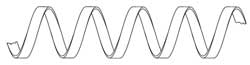
Figure 1 Simple helix slow wave structure (top) and photograph of a tungsten helix structure (bottom).
The ‘simple’ helix continues to be the most commonly used SWS in TWTs since its inception by Kompfner. In its simplest form, a wire or tape wound in the form of a helix, it exhibits the greatest potential of all SWSs, in terms of dispersion control and thus greatest operating bandwidth. Performance characteristics can be controlled through the design of simple and complex pitch tapering, to enhance both narrow and broadband operation, optimising gain, power and efficiency. Figure 1 shows both a sketch of a simple helix structure and a photograph of a tungsten tape helix.
Dispersion characteristics can be controlled through design of helix supports, in terms of material choice and cross-sectional shape and electrically conductive dispersive vanes. Vanes offer the greatest opportunity for dispersion control and are commonly utilized within broadband TWTs of greater than an octave bandwidth.
Bifilar Contra-wound and Ring-bar TWTS
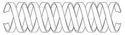
Figure 2 SBifilar contra-wound (top) and ring-bar (bottom) slow wave structures.
Variants on the simple helix include the bifilar helix (made up of two contra-wound helices of equal but reversed pitch), the ring-bar and the ring-loop structure. Sketches of both bifilar and ring-bar structures can be seen in Figure 2 . These types of structures enable higher power handling through both thermal capability and higher voltage operation without giving rise to backward wave oscillation (BWO), a major constraint in simple helix structures. The downsides to these types of structures (in relation to the simple helix) are the limitation of bandwidth due to the high dispersion characteristics of the SWS and the increased complexity in manufacture, which directly impacts the cost.
Coupled Cavity TWTs
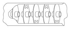
Figure 3 Slotted (top) and clover-leaf (bottom) coupled cavity slow wave structures.
The feature that distinguishes the coupled cavity TWT from other types is the SWS, which consists of a series of cavities, is coupled by slots. The benefits of this are that the cavities can be designed to operate with high voltage electron beams enabling peak output powers of 10s to 100s of kilowatts, with high average powers. The space harmonic coupled cavity circuit, favoured by most users because of the high (up to 20 percent) instantaneous bandwidth achievable, is particularly suited to integration of periodic permanent magnetic (PPM) focussing. The result is a very compact device that is used in mobile radar systems. Very high average power and CW coupled cavity TWTs are available but these utilise solenoid focussing, which requires significant electrical power and weighs more than PPM focussed devices. Figure 3 shows two of the more commonly used coupled cavity type structures: slotted and clover-leaf.
Cathode Technology
Developments in the field of emitters, the electron source of travelling wave tubes, have enabled the development of devices capable of 10s and even 100s of thousands of hours of life. Fifty years ago the electron sources used in vacuum devices, including the early TWTs, would have been of the oxide-coated type emitter, restricted to pulsed or low current density CW applications, ideally suited to high-power pulsed devices, like the coupled cavity TWT, used for radar-type applications.
Today, with advances in cathode technology, materials and processing, a range of impregnated tungsten matrix cathodes are the cathode of choice. Capable of considerably higher mean currents, operating CW at high current densities (> 20 A/cm 2 ), the coated tungsten matrix (M-type) cathode is the most commonly used. Other advantages over the oxide cathode include higher resistance to poisoning, increased life and improved manufacturing tolerances because of the machined emitting surface.
In addition to this, coupled with a potted heater assembly, cathodes have been manufactured to survive and function under the most severe vibration and shock levels.
Work continues towards making advances in cathode design and manufacture. Developments include mixed-matrix and reservoir cathodes, and more recently the field emitting cold cathode. 4 Although in its infancy, recent research has produced samples nearing the capabilities required for a TWT electron source.
TWT Design and Validation
The introduction of computer modelling and its advances over the past three decades have had a marked impact on the vacuum electronics industry, taking design from long-hand calculations (sometimes only comprehendible to the most advanced mathematicians) to user-friendly computer simulation of all aspects (electronic, mechanical, thermal) of the device design.
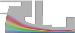
Figure 4 OPERA 2D finite element software-electron gun model.
3-D electron beam simulation programmes enable accurate simulation of beam entry, focussing systems and collection. Figure 4 shows a plot from an electron gun model, using OPERA 2D. Together with the constant advances in computing power, designs can be realised in hours or even minutes, and once validated, the latest software is capable of previously unprecedented levels of accuracy.
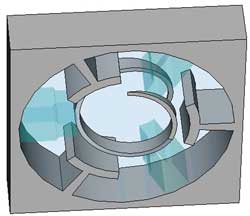
Figure 5 Microwave Studio parametric model of a helix SWS.
Advances in Particle in Cell (PIC) and parametric codes, combined with complex optimisers, enables accurate simulation of the interaction between electron beam and the slow wave structure. Increases in computing power have enabled the simulation of complex slow wave structures and complete RF circuits. Figure 5 is a cross-section of a helix SWS, showing dielectric helix support rods and dispersion vanes, typically used in broadband helix TWTs.
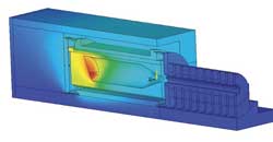
Figure 6 3D thermal simulation model of TWT collector assembly.
In addition to the advances in electrical design enabled by new codes and improved processing speeds, commercially available codes can be utilised for thermal and mechanical stress analysis. Thermal analysis of TWT collectors enables improved thermal management of new designs. Figure 6 shows a simple thermal model of a single stage collector. The modern-day designer now has a complete package of modelling and simulation codes that, when fully validated with real device data, enable a right-first-time design approach significantly reducing development times and costs.
Present State of the TWT Art
TWT production is limited to a handful of manufacturers throughout the world; major suppliers include CPI, L-3 and Teledyne in the US, e2v, Thales and TMD in Europe, NEC in Japan, and several developing manufacturers in both India and China.
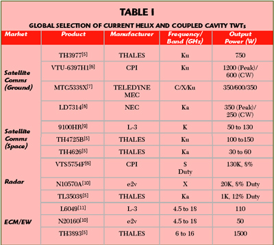
Table 1 Global Selection of Current Helix and Coupled Cavity TWTs
Determining the current state of the art is difficult; many government-funded programmes restrict the publication of data and commercial confidentiality is high due to the competitive markets. Table 1 shows a cross-section of products from various manufacturers, giving a broad view of current capabilities.
Satellite Communications (Ground-based)
Low cost, high reliability and high linearity are key in this commercially competitive market. Offerings are available from all the major manufacturers, whether it is earth stations, Satellite News Gathering (SNG) mobile systems, network hubs or small lightweight flyaway pack systems. Demands for bandwidth are forcing the move towards higher frequencies (Ka-band) and the onset of digital broadcasting requires higher powers.
Notable performance advances have been achieved by NEC and L-3 in the development of Ka-band helix TWTs for this market, with CW power levels as high as 500 W. Another growth area is in small lightweight amplifiers used in flyaway and hand portable systems. Reductions in luggage weight, by most airlines around the world, has forced demand for these systems to become smaller and lighter. In a market where solid state amplifiers and travelling wave tube amplifiers (TWTA) compete head to head, e2v has launched a range of TWTAs (StellarMini™) that are the smallest and lightest currently available.
Advances in multi-octave TWTs developed originally for military applications has lead to opportunities in multi-band TWTAs for both commercial and military communications. Dual- and tri-band devices have been developed by Teledyne, CPI and e2v.
Satellite Communications (Space)
Key attributes of the space TWT include long life (mission life greater than 20 years), high reliability, low power consumption (high efficiency) and low mass. The majority of all TWTs in space have been manufactured by Thales (France) or L-3 Electron Technologies Inc. (US; formerly Boeing/Hughes) with developments progressing at CEERI (India).
Future demand is moving up in frequency as advances in solid state technology capture the low frequency end of the operating spectrum (up to Ku-band) and the overcrowding of traditional bands forces the need for greater bandwidth utilization. The number of satellites being launched at Ka-band is growing fast and is set to continue.
Traditionally the realm of high peak power helix and coupled cavity TWTs, the development of active phased-array radar has seen a significant shift away from vacuum devices towards solid state technology, more suited to compact packaging required in an array system.
Although as requirements become more demanding, requiring higher efficiency, lower thermal dissipation and greater reliability, customers of microwave amplifiers are turning back to TWTs as the preferred option. Over the past three decades TWT reliability has increased considerably; space TWTs have achieved MTBFs of six million hours with efficiencies reaching 50 percent, which makes the TWT a viable alternative to solid-state amplifiers (SSA). Advances in mini TWT technology, driven by airborne towed decoys and MPMs, has lead to compact high efficiency devices ideally suited to phased-array and Synthetic Aperture Radar (SAR) applications.
The largest market for the helix TWT is in ECM and EW applications, which has seen tens of thousands of devices built into expendable decoy systems and ECM pods around the world. The demands on devices tend to be a combination of those for all other applications, with the added complexity of operation over multi-octave bandwidths. Current demands are for greater bandwidth and higher efficiency in smaller lighter weight packages that are able to operate over extreme temperature ranges and high altitudes. With the growth of unmanned air vehicle (UAV) applications, the military business for TWTs continues to grow.
Over the past decade, the likes of L-3, CPI, Thales and e2v have developed ranges of mini TWTs, predominantly for airborne applications with bandwidths of greater than 2 octaves covering 4.5 to 18 GHz and power levels now exceeding 100 W CW across the full band. Devices have been proven to survive and operate at temperatures ranging from –55° to > 150°C, altitude > 70 kft and shock levels in excess of 500 G.
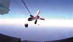
Figure 7 Deployed fibre optic towed decoy.
Utilization of multi-stage depressed collectors has seen mid-band efficiencies top 50 percent, resulting in reduced thermal footprints and prime power requirements. CPI 12 has, over the past two decades, delivered many thousands of mini TWTs into the Raytheon 12 Goleta ALE-50 towed decoy programme, which is a notable achievement. Figure 7 shows a typical fibre optic towed decoy (FOTD) TWT platform being deployed.
Advances continue to be made at higher frequencies covering the 18 to 40 GHz band for countering and jamming new threats. With continually changing and advancing threats, plus the upgrades to existing systems, demands on the microwave amplifiers in this market are increasing, continuing to enhance efficiency and expand bandwidth will be necessary to keep ahead of the advancing SSA sector and meet the expectations of customers.
Status of Coupled Cavity TWTs
Many modern radar systems, including new developments, continue to use coupled cavity TWTs. This is because, contrary to popular opinion, coupled cavity TWTs are often more robust, long-lived, reliable and efficient than the solid state alternative. Coupled cavity TWTs currently manufactured cover the frequency ranges from D-band up to M-band. Instantaneous bandwidth of 10 percent is required for most applications, but various techniques have been employed to increase this to 20 percent (normally compromising efficiency or power considerations).
The conventional manufacturing technique for coupled cavity TWTs employs individual cavities and coupling plates brazed together. At Ka-band and above, this technique becomes very expensive, as the machining tolerances become extremely tight.
Alternative methods of production for high frequency TWTs have been investigated, with the ladder structure used by CPI being the most popular. Modern computer aided design techniques have been used to redesign existing coupled cavity TWT designs; the result of this has been much higher manufacturing reproducibility, and hence yields. 13
New radar transmitter specifications continue to demand more from the TWT designer; the areas of particular interest are higher mean power, faster warm-up time and higher efficiency. The use of computer aided design tools to investigate these areas has been successfully employed. Notably, e2v has developed and built RF circuits for high mean power that overcome the natural limitation of heat being conducted through iron pole pieces. 14 Other manufacturers have increased mean power by improving the electron beam confinement under RF conditions. There is no reason why both techniques cannot be combined to produce coupled cavity TWTs of higher mean power capability.
Future Developments
Figure 8 Frequency and power capabilities of present amplifier technologies.
With the recent development of compound semiconductors into the power amplification domain, a number of power applications have now migrated from tube-based to solid state amplification. This is especially true of sub-kilowatt, narrow-band requirements, with recent developments in Silicon Carbide (SiC) and Gallium Nitride (GaN) extending these devices into multiple-kilowatt capability, to frequencies around 10 GHz and above. 15 Figure 8 shows the current solid-state and vacuum tube landscape, with respect to frequency and power.
As solid-state devices increase in capability, more applications will migrate from a tube to a transistor embodiment. However, for the present it is clear that travelling wave tubes continue to offer a compact and efficient amplifier solution, particularly under harsh operating environments. TWT amplifiers can also span a broad frequency bandwidth, approaching three octaves of coverage from a single tube.
Future Direction for TWTs
The future remains bright for TWTs, albeit in a tougher and more competitive market place. The continued progress of solid-state amplifiers will eat into the edges of the TWT domain, but there will remain to be requirements for the amplification of microwaves beyond the present capabilities of solid-state.
For systems with limitations on size, weight, power dissipation and consumption, there are, and will continue to be, numerous applications for vacuum electronic devices (VED). Higher power levels and higher frequencies are areas where tubes have no equal. The continued advances in VED technology will sustain growth.
In the commercial market, High Definition Television (HDTV) and the onset of the digital age are demanding higher powers and higher frequencies. These are major opportunity areas for the TWT.
The defence business worldwide continues to grow, upgrades to existing systems and new platforms, such as UAVs, require higher efficiencies, smaller lighter payload packages and improved reliability. Higher definition radar systems such as SARs and phased-array radar offer opportunities for small, lightweight, high-efficiency devices. Also, government and defence funding is being made available to the industry to continue developing products for the future. An area of considerable interest at present is in the terahertz and sub mm-wave frequency regimes. Research and development in this area include CAD design of MEMS type structures, manufacturability, detection techniques and prototype manufacture. Programmes are as yet undefined but potential uses include UAV SAR for tactical targeting and terrain avoidance and security imaging. 16
Acknowledgments
Inputs on TWT product history and technology development have been provided by Alan Griggs (e2v principal TWT engineer) and Ian Milsom (e2v cathode development and test manager). The overview of current power amplifier technology was compiled by Dr. Cliff Weatherup (e2v strategic technology manager) and Dr. Trevor Cross (e2v chief technology officer). Product and application photographs were provided by Andy Bennett (e2v marketing).
1. R. Kompfner, Travelling Wave Electronic Tube , US Patent no. 2630544, Filed 20th March 1948, Issued 3rd March 1953. 2. J.R. Pierce, “Travelling-wave Tubes,” Proc. IRE , Vol. 35, No. 2, February 1947, pp. 108-111 . 3. E.J. Nalos, “Present State of Art in High Power Travelling-wave Tubes: Part I,” Microwave Journal , Vol. 2, No. 12, December 1959, pp. 31-38. 4. D.R. Wahley, et al., “Operation of a Low Voltage High-transconductance Field Emitter Array TWT,” Proc. IEEE Vacuum Electronics Conference , April 22-24, 2008, pp. 78-79. 5. Product data from Thales web site: http://components-subsystems.thales-catalogue.com . 6. Product data from CPI, Microwave Power Products Division web site: http://www.cpii.com/product.cfm/1/19/65 . 7. Product data from Teledyne MEC web site: http://www.teledyne-mec.com/products/productCatalog.aspx . 8. Product data from NEC Microwave Tube web site: http://www.nec-mwt.com/english/products/twt/seihin/index.html . 9. Product data from L-3 Electron Technologies Inc. web site: http://www.l-3com.com/eti/product_lines_space_twt.htm . 10. Product Data from e2v. 11. Product Data from L-3, Electron Devices web site: http://www.l-3com.com/edd/products_mini_tubes.htm . 12. ALE-50 Contract reference, Business Journal, September 19, 2007, http://www.bizjournals.com/sanjose/stories/2007/09/17/daily44.html?ana=from_rss . 13. C. Ar, A.V. Piring and P. Tibbs, “F-Programs TWT Design Upgrades,” Proc. IEEE Vacuum Electronics Conference , April 27-29, 2004, pp. 20-21. 14. A. Griggs, “A New Coupled Cavity Circuit for High Mean Power Travelling-wave-Tubes,” IEEE Transactions on Electron Devices , Vol. 38, No. 8, August 1991, pp. 1952-1957. 15. R. Trew, “Wide Bandgap Semiconductor Transistors for Microwave Power Amplifiers,” IEEE Microwave Magazine , Vol. 1, No. 1, March 2000. 16. M.J. Rosker and H.B. Wallace, “Vacuum Electronics and the World Above 100 GHz,” Proc. IEEE Vacuum Electronics Conference , April 22-24, 2008, pp. 5-7.

Report Abusive Comment
Restricted Content
You must have JavaScript enabled to enjoy a limited number of articles over the next 10 days.
- Microwave Engineering Tutorial
- Microwave Engineering - Home
- Introduction
- Transmission Lines
- Modes of Propagation
- Types of Transmission Lines
- Avalanche Transit Time Devices
- Microwave Devices
- E-Plane Tee
- H-Plane Tee
- E-H Plane Tee
- Rat-race Junction
- Directional Couplers
- Cavity Klystron
- Reflex Klystron
Travelling Wave Tube
- Measurement Devices
- Measurements
- Example Problems
- Microwave Engineering Resources
- Quick Guide
- Microwave Engineering - Resources
- Microwave Engineering - Discussion
- Selected Reading
- UPSC IAS Exams Notes
- Developer's Best Practices
- Questions and Answers
- Effective Resume Writing
- HR Interview Questions
- Computer Glossary
Travelling wave tubes are broadband microwave devices which have no cavity resonators like Klystrons. Amplification is done through the prolonged interaction between an electron beam and Radio Frequency (RF) field.
Construction of Travelling Wave Tube
Travelling wave tube is a cylindrical structure which contains an electron gun from a cathode tube. It has anode plates, helix and a collector. RF input is sent to one end of the helix and the output is drawn from the other end of the helix.
An electron gun focusses an electron beam with the velocity of light. A magnetic field guides the beam to focus, without scattering. The RF field also propagates with the velocity of light which is retarded by a helix. Helix acts as a slow wave structure. Applied RF field propagated in helix, produces an electric field at the center of the helix.
The resultant electric field due to applied RF signal, travels with the velocity of light multiplied by the ratio of helix pitch to helix circumference. The velocity of electron beam, travelling through the helix, induces energy to the RF waves on the helix.
The following figure explains the constructional features of a travelling wave tube.

Thus, the amplified output is obtained at the output of TWT. The axial phase velocity $V_p$ is represented as
$$V_p = V_c \left ( {Pitch}/{2\pi r} \right )$$
Where r is the radius of the helix. As the helix provides least change in $V_p$ phase velocity, it is preferred over other slow wave structures for TWT. In TWT, the electron gun focuses the electron beam, in the gap between the anode plates, to the helix, which is then collected at the collector. The following figure explains the electrode arrangements in a travelling wave tube.

Operation of Travelling Wave Tube
The anode plates, when at zero potential, which means when the axial electric field is at a node, the electron beam velocity remains unaffected. When the wave on the axial electric field is at positive antinode, the electron from the electron beam moves in the opposite direction. This electron being accelerated, tries to catch up with the late electron, which encounters the node of the RF axial field.
At the point, where the RF axial field is at negative antinode, the electron referred earlier, tries to overtake due to the negative field effect. The electrons receive modulated velocity. As a cumulative result, a second wave is induced in the helix. The output becomes larger than the input and results in amplification.
Applications of Travelling Wave Tube
There are many applications of a travelling wave tube.
TWT is used in microwave receivers as a low noise RF amplifier.
TWTs are also used in wide-band communication links and co-axial cables as repeater amplifiers or intermediate amplifiers to amplify low signals.
TWTs have a long tube life, due to which they are used as power output tubes in communication satellites.
Continuous wave high power TWTs are used in Troposcatter links, because of large power and large bandwidths, to scatter to large distances.
TWTs are used in high power pulsed radars and ground based radars.
To Continue Learning Please Login
A high-power, traveling wave tube amplifier
Ieee account.
- Change Username/Password
- Update Address
Purchase Details
- Payment Options
- Order History
- View Purchased Documents
Profile Information
- Communications Preferences
- Profession and Education
- Technical Interests
- US & Canada: +1 800 678 4333
- Worldwide: +1 732 981 0060
- Contact & Support
- About IEEE Xplore
- Accessibility
- Terms of Use
- Nondiscrimination Policy
- Privacy & Opting Out of Cookies
A not-for-profit organization, IEEE is the world's largest technical professional organization dedicated to advancing technology for the benefit of humanity. © Copyright 2024 IEEE - All rights reserved. Use of this web site signifies your agreement to the terms and conditions.
On the Theory of a Hybrid of a Travelling Wave Tube with a Photocathode and an Amplifier with Complex Permittivity
- Published: 16 March 2021
- Volume 85 , pages 76–82, ( 2021 )
Cite this article

- A. A. Funtov 1
41 Accesses
Explore all metrics
A theory is presented for a hybrid of a photocathode with a Travelling Wave Tube (TWT) and an amplifier with complex permittivity. A linear theory of an amplifier with complex permittivity is used in the section with complex permittivity, and the linear theory of TWT is used in the TWT section. Defined motion and the given current are used to construct a nonlinear theory.
This is a preview of subscription content, log in via an institution to check access.
Access this article
Price includes VAT (Russian Federation)
Instant access to the full article PDF.
Rent this article via DeepDyve
Institutional subscriptions
Transparent Traveling-Wave Tubes with Multivelocity Electron Beams
Transparent traveling wave tubes with electron-beam modulation at the cathode, multiphase oscillator using traveling pulses developed in a system of transmission lines with regularly spaced resonant-tunneling diodes.
It is worth noting that QC decay is a phenomenon in photo-TWT that is due to the decay of the high-frequency component of the current at a certain length of the TWT (and thus R eq ) as a result of space charge effects. In contrast to the classical TWT, the phase difference between the current and the field is not constant because of space charge effects and varies with the length of the TWT (it pulsates). If the TWT is short, the current and the field are opposite in phase. A similar effect can be observed when the phase difference of the high-frequency components of the velocity and beam current is nonzero.
Duan, Z., Shapiro, M.A., Gong, Y., et al., Proc. 19th IEEE Int. Vacuum Electronics Conf. , Monterey, 2018.
Lu, X., Hummelt, J.S., Shapiro, M.A., et al., Proc. 18th IEEE Int. Vacuum Electronics Conf. , London, 2017.
Rowe, T., Behdad, N., and Booske, J., IEEE Trans. Plasma Sci. , 2015, vol. 43, no. 7, p. 2123.
Article ADS Google Scholar
Rowe, T., Behdad, N., and Booske, J., IEEE Trans. Plasma Sci. , 2016, vol. 44, no. 10, p. 2476.
Lu, X., Stephens, J.C., Mastovsky, I., et al., Phys. Plasmas , 2018, vol. 25, 023102.
Jeannin, M., et al., Proc. 20th Int. Vacuum Electronics Conf. , Busan, South Korea, 2019.
Kasatkin, L.V., Radiotekh. Elektron. (Moscow) , 1961, vol. 6, no. 2, p. 267.
Google Scholar
Shevchik, V.N. and Trubetskov, D.I., Analiticheskie metody rascheta v elektronike SVCh (Analytical Methods of Calculation in Microwave Electronics), Moscow: Sov. Radio, 1970.
Tseitlin, M.B. and Kats, A.M., Lampa s begushchei volnoi (Travelling Wave Tube), Moscow: Sov. Radio, 1964.
Download references
This work was supported by the Russian Foundation for Basic Research, project no. 18-02-00666.
Author information
Authors and affiliations.
Saratov State University, 410012, Saratov, Russia
A. A. Funtov
You can also search for this author in PubMed Google Scholar
Corresponding author
Correspondence to A. A. Funtov .
Additional information
Translated by I. Obrezanova
About this article
Funtov, A.A. On the Theory of a Hybrid of a Travelling Wave Tube with a Photocathode and an Amplifier with Complex Permittivity. Bull. Russ. Acad. Sci. Phys. 85 , 76–82 (2021). https://doi.org/10.3103/S1062873821010111
Download citation
Received : 20 July 2020
Revised : 28 August 2020
Accepted : 28 September 2020
Published : 16 March 2021
Issue Date : January 2021
DOI : https://doi.org/10.3103/S1062873821010111
Share this article
Anyone you share the following link with will be able to read this content:
Sorry, a shareable link is not currently available for this article.
Provided by the Springer Nature SharedIt content-sharing initiative
- Find a journal
- Publish with us
- Track your research
Ukraine-Russia war latest: Kremlin responds to claims Russia is targeting Olympics
After reports that Moscow is targeting the Paris Olympics with a disinformation campaign, the Kremlin has responded. Meanwhile, NATO only has two to three years to prepare before Russia regains its ability to launch a conventional attack on the alliance, Norway's top general has said.
Tuesday 4 June 2024 18:07, UK

- Big picture: Everything you need to know about the war right now
- Kremlin denies disinformation campaign targeting Olympics
- Russia could be ready to attack NATO in three years, Norway warns
- Baby among seven civilians injured in overnight missile strike
- Navalny's mother and supporters visit grave on his birthday
- Live reporting by Bhvishya Patel
We're pausing our coverage for today but we will be back tomorrow with more updates.
Here is a rundown of the key developments today:
- Norway's top general said NATO only has two to three years to prepare before Russia regains its ability to launch a conventional attack on the alliance;
- German Chancellor Olaf Scholz said Ukraine's use of Western-supplied weapons to strike targets in Russia will not "contribute to escalation";
- Microsoft made allegations in the New York Times that Russia was targeting the upcoming Olympics with a disinformation campaign;
- The mother of Alexei Navalny and his supporters visited his grave to lay flowers and pay tribute to the late Kremlin critic on what would have been his 48th birthday.
You can scroll back through the blog to read all our updates from today.
Kremlin spokesman Dmitry Peskov has said any foreign military staff training Ukrainian troops will not have any "immunity" from Russian strikes.
"Any instructors who train the Kyiv regime's troops don't have any sort of immunity," he said in a conference call with reporters today.
Reports have suggested talks are ongoing over whether French instructors could soon be sent to support training centres in Ukraine.
Ukrainian troops have been preparing to fire towards Russian positions on the frontline in the eastern Donetsk region.
Donetsk is one of the four provinces Vladimir Putin proclaimed as part of Russia in an illegal referendum at the start of the war and fighting here is particularly intense.
Russia's two biggest banks plan to open branches and offices in the regions of Ukraine that Moscow claimed to have annexed next month.
Sberbank chief executive German Gref said in Russia's upper house of parliament the bank would be "present throughout the whole country's territory".
VTB chief executive Andrei Kostin said they would open two offices in Luhansk in July and had plans to start serving clients in Donetsk and the port city of Mariupol by the end of the year.
For context : Vladimir Putin illegally annexed Ukraine's Donetsk, Luhansk, Kherson and Zaporizhzhia regions in September 2022, after what Ukraine and its Western allies branded sham referendums.
The move was condemned by many countries as illegal.
Russian forces only partly control the four regions.
Manufacturers and distributors need to improve compliance with Russia-related sanctions, the deputy secretary of the US Treasury has said.
American companies in particular need to pay more attention to their supply chains to ensure they are not complicit with Russia's evasion of sanctions over Ukraine, Wally Adeyemo said in an interview with CNBC.
He said manufacturers of microelectronics and machine tools especially needed to step up compliance to help cut off supplies of "dual use" goods to Russia, including from Chinese producers.
Freight forwarders and distributors need to do the same and financial institutions need to look at their relationships with small and medium-sized banks in "countries of concern" because Moscow is looking for ways around US sanctions, Mr Adeyemo said.
Volodymyr Zelenskyy's chief of staff has said that using Western weapons to strike inside Russia was a vital decision that would impact Moscow's tactical aviation and its offensive ability in border regions.
"This will impact the conduct of the war, planning of counteroffensive actions, and will weaken Russians' abilities to use their forces in the border areas," Andriy Yermak said on Telegram.
Russia has said the move would mark an escalation to the conflict and has threatened war with NATO if Western weapons are used in its airspace.
By Ivor Bennett , Moscow correspondent
Dozens of Alexei Navalny supporters have visited his grave to lay flowers and pay tribute to the late Kremlin critic on what would have been his 48th birthday.
The opposition leader died at an Arctic prison colony in February, prompting outrage from Western governments.
Nearly four months on, his family say the cause of his death remains unexplained.
His widow Yulia Navalnaya has accused Vladimir Putin of ordering his murder, and last week his allies called for additional sanctions to punish the Russian president's inner circle.
The Kremlin has repeatedly denied any involvement in his death. According to his death certificate, he died of natural causes.
Navalny's mother, Lyudmila, as well as his mother-in-law Alla Abrosimova, were among those who gathered at his grave in the Borisovskoye cemetery in southeast Moscow today.
Video posted by SOTAvision on the social media platform Telegram shows a memorial service led by Dmitry Safronov, a priest who was previously banned from clerical duties by the Russian Orthodox Church for presiding over a similar service in March, which marked 40 days since the activist's death.
According to the independent Novaya Gazeta newspaper, three police officers were on duty near the cemetery but they did not make any arrests.
Having been convicted of multiple charges, ranging from fraud to extremism, Navalny was serving sentences totalling more than 30 years when he died.
His Anti-Corruption Foundation (FBK) is outlawed in Russia, and has been accused by the authorities of having links to the CIA.
What remains of his team now operates in exile.
Polish farmers have resumed their protest blockade at the Ukrainian border crossing due to agricultural imports from the country.
Farmers in Poland have staged sporadic demonstrations at the border since last autumn.
The demonstrators are blocking trucks from leaving Ukraine.
Cargo vehicles heading to Ukraine are allowed to enter by 12 trucks per 12 hours and by four trucks with humanitarian aid per hour, the Ukrainian Border Guard Service said.
Other vehicles are continuing as usual.
"Representatives of Polish farmers demand reduced imports of Ukrainian crops to Polish territory from Ukraine," the Border Guard Service said.
Disputes over crop imports have strained the relationship between Warsaw and Kyiv, with both countries being major agricultural producers.
Polish farmers have complained that Ukrainian products create uneven competition, particularly since the EU lifted tariffs in 2022.
Poland banned the import of several products from Ukraine, including grain, corn, and rapeseed, in 2023.
In our last post, we brought you news that Microsoft had made allegations in the New York Times that Russia was targeting the upcoming Olympics with a disinformation campaign.
Moscow has now branded those accusations "absolute slander", with Kremlin spokesman Dmitry Peskov saying there is no substance to them.
Russia is widely accused of having waged disinformation campaigns over the years, often targeting elections in the United States, Europe and Britain.
Moscow has always denied it uses disinformation to influence public opinion.
The Paris Olympics are being targeted by a Russian-linked disinformation campaign, according to the New York Times.
Since last summer, efforts have been under way by a hacker group named Storm-1679, the paper reports.
The campaign "began in earnest" when a documentary was released with a doctored International Olympic Committee (IOC) logo, along with an AI-powered impersonation of Tom Cruise's voice.
The hackers "are trying to cultivate an anticipation of violence", said Clint Watts, the head of Microsoft's Digital Threat Analysis Centre.
"They want people to be fearful of going to the Olympics."
Storm-1679 makes around three to eight disinformation videos a week, Mr Watts told the newspaper, many of which appear as if they come from media outlets such as the BBC or Al Jazeera.
Both Russia and Belarus have been banned from competing in the Olympics over the war in Ukraine, but some athletes from those countries will be allowed to compete as "neutral athletes", the IOC announced in March.
The Paris games will take place between 26 July and 11 August.
Be the first to get Breaking News
Install the Sky News app for free

Arrests of Russian generals and officials raises questions about Putin's war machine
- Five senior figures in Russia's defense establishment have been arrested on corruption charges.
- A former UK defense attaché in Moscow described corruption as a "cancer" within Russia's MOD.
- The arrests follow the replacement of Sergei Shoigu as defense minister.
It began with Timur Ivanov, Russia's then-deputy defense minister, who was arrested after being accused of taking bribes "on a particularly large scale."
Then came Lt. Gen. Yuri Kuznetsov, head of the defense ministry's personnel directorate. He was arrested after more than 100 million rubles (over $1 million), gold coins, and other valuables were seized from his residences.
That was followed by the arrests of the ex-commander of the 58th Guards Combined Arms Army, Ivan Popov, and later Lt. Gen. Vadim Shamarin and defense ministry official Vladimir Verteletsky .
The wave of arrests came as part of a push to stamp out corruption in Russia's defense ministry, which, according to the UK Ministry of Defence, "is deeply rooted."
John Foreman, a former British defense attaché in Moscow, described corruption as a "cancer" within Russia's MOD, adding that the arrests and ministry reshuffle suggest that things aren't going to plan for Russia.
"You don't remove your defense minister and replace all your generals if everything is going well," Foreman told Business Insider.
Mark Galeotti, an honorary professor at University College London and senior research associate at the UK-based think tank the Royal United Services Institute, told BI he believed the clear-out was connected with the change in defense minister.
"Putin has been very disinclined to reshuffle the top tier of his security agencies in the middle of a war," Galeotti said.
But his inauguration for a fifth presidential term "provided a moment where he really felt he had to move Shoigu on," he added.
"If they're bringing in Belousov with a mandate to get absolute control of the defense ministry's finances, to cut down on waste and embezzlement, then now is the time to tackle the whole problem," he continued.
In a 2022 report , experts told the Organised Crime and Corruption Reporting Project that corruption was so rife among Russian forces that it could ultimately save Ukraine.
Following the launch of Russia's full-scale invasion of the country in February 2022, a former Russian foreign minister also claimed that widespread corruption was among the reasons for the Russian military's poor performance in the early days of the conflict.
Andrey Kozyrev, who served as the foreign minister under President Boris Yeltsin in in 1990s, wrote on X: "The Kremlin spent the last 20 years trying to modernize its military. Much of that budget was stolen and spent on mega-yachts in Cyprus. But as a military advisor you cannot report that to the President. So they reported lies to him instead."
Belousov's appointment is, therefore, an attempt by Putin to gain control of these high levels of corruption that Shoigu and, until now, Putin himself have allowed to occur, Foreman told BI.
"Putin has tolerated Shoigu building his empire, taking money from the defense budget, installing his corrupt cronies in return for loyalty," he said.
Related stories
Putin now needed someone who would bring "more bang for the buck," he added.
Echoes of Wagner criticisms
Yevgeny Prigozhin, the former leader of the mercenary Wagner Group who was killed in a plane crash in August last year, had previously hit out at Shoigu and Valery Gerasimov, Russia's Chief of the General Staff, accusing them of incompetence and corruption.
"Shoigu! Gerasimov! Where the fuck are the munitions?!" he shouted in one video, blaming the officials for some of the losses suffered by his Wagner Group.
Prigozhin is losing it. "Shoigu! Gerasimov! Where the f*$k are the munitions!" He directly calls them "b*tches." Makes you wonder what 'coup' Wind of Change is referring to that FSB resources have been redirected to prevent. pic.twitter.com/tyjpjDUWQK — Igor Sushko (@igorsushko) May 4, 2023
While Putin stood with Shoigu at the time, it was likely his "nail in the coffin as defense minister," Foreman said.
"The drip of accusations of corruption, the blatant nature of it at a time when Putin was demanding more and more sacrifice for the cause of the war, was not good," he said.
For a while, it meant that Shoigu was safer than ever because "Putin couldn't seem to be giving into Prigozhin's demands," Galeotti said. There needed to be "time for the dust to settle."
But Prigozhin "was actually telling the truth about some of these things. And for an authoritarian regime that depends on information control, nothing is more dangerous than the truth," he added.
Russia's top general could be next on Putin's list
Valery Gerasimov, Russia's top general, has been found wanting in his role as Russia's Chief of the General Staff, defense experts say.
"He's 68, unpopular and incompetent and there's a new defense minister: he has lost his cover," Foreman said, adding that there are also "credible alternatives."
Both Galeotti and Foreman said they would be surprised if Gerasimov remained in place by the end of the year.
Witn Shoigu gone, the speed and frequency of arrests in the defense ministry can now pick up.
Last week a Kremlin source told The Moscow Times that "the FSB is mopping up Shoigu's team. It's to be expected. This kind of operation can only be carried out with approval at the very top."
"Criminal cases have been piled up. But while Shoigu was a minister and had enormous influence, investigators were not allowed to pursue them," a second government official told The Moscow Times.
The UK MOD has also said that it "is likely that there will be further arrests," while one acting Russian government official told The Moscow Times that the moves could become part of the "largest purges" in modern Russian history.
Galeotti said that any such further arrests would likely aim at sending senior military figures a clear message: "You could be next."
But a solution to the problem would require a complete upheaval of the whole defense structure, and "that's not going to happen," Galeotti said. "It is an attempt to redefine the acceptable levels of corruption."
Watch: The 24-hour mutiny that could bring down Putin
- Main content
IMAGES
VIDEO
COMMENTS
A traveling-wave tube ( TWT, pronounced "twit" [1]) or traveling-wave tube amplifier ( TWTA, pronounced "tweeta") is a specialized vacuum tube that is used in electronics to amplify radio frequency (RF) signals in the microwave range. [2] It was invented by Andrei Haeff around 1933 as a graduate student at Caltech, and its present form was ...
A travelling wave tube is a high power amplifier used for the amplification of microwave signals up to a wide range. It is a special type of vacuum tube that offers an operating frequency ranging between 300 MHz to 50 GHz.. Travelling wave tubes are non-resonant structures that offer continuous interaction of applied RF field with the electron beam over the entire length of the tube.
Traveling Wave Tubes offer several advantages over other microwave amplification technologies, such as solid-state amplifiers and klystrons. Some of the key benefits include: Wide Frequency Range: TWTs can operate over a broad range of frequencies, typically from 0.3 GHz to 50 GHz or higher. This makes them suitable for a wide variety of ...
A Traveling-Wave Tube or TWT Amplifier is a high power, high-frequency amplifier that is built using traveling wave tubes. A traveling-wave tube is a type of vacuum tube used to amplify high-frequency signals. The RF signal is amplified by absorbing power from a beam of electrons as it goes through the tube. TWTAs usually operate from 300 MHz up to frequencies over 100 GHz (there are cases ...
The traveling-wave tube (TWT), also known as the traveling-wave amplifier (TWA) or traveling-wave tube amplifier (TWTA), is a widely used amplifier in satellite communications and radar. An electromagnetic signal is inputted on one end of the device and is amplified over a distance until it is extracted downstream at the output. The physics ...
NASA Glenn Research Center. First developed in the 1930s, Traveling-Wave Tube Amplifiers (TWTAs) were designed to amplify radio frequency signals. It was in the early 1960s that NASA and L3 teamed up to evolve the technology so it would meet the transmission needs of space missions. The first TWTA flew on a satellite in 1962, and they have been ...
The Basics of Travelling Wave Tube Amplifiers SCM01 Roberto Dionisio, Claudio Paoloni European Space Agency Lancaster University [email protected] [email protected] ... 17:25 - 18:10 Traveling Wave Tube Design with Simulation Monika Balk, CST AG, Darmstadt, Germany 18:10 - 18:20 Open discussion and concluding remarks . Slide 1
Today, Thales is the world's leading supplier of traveling wave tubes for space, defence and satcom markets. Most data sent by satellites today uses a Thales amplifier. Many thousands of Thales TWTs have been launched into orbit since 1974 providing over 900 million hours of operation. They are even helping to transmit data from the Exo Mars ...
In 2020, the traveling wave tube amplifier was added to the Space Foundation's Space Technology Hall of Fame. And as of 2022, the TWT on Voyager 2 is still plugging away, transmitting data as it continues to make the journey through interstellar space. "Nobody can explain why the Voyager TWT is still working," said Harvey.
Traveling Wave Tubes: Modern Devices and Contemporary Applications. From its conception in 1943 by Dr. Rudolf Kompfner in England, 1 and later its development by Kompfner and John R. Pierce at the Bell Laboratories in the United States, 2 the travelling wave tube (TWT) has become the microwave amplifier of choice for many commercial and ...
Kory, C. L. et al., ' Traveling-wave tube amplifier model to predict high-order modulation intersymbol interference ', in Third IEEE International Vacuum Electronics Conference, Monterey, CA, pp. 308 - 309, 2002.Google Scholar
Traveling wave tube amplifiers (TWTAs) and solid-state power amplifiers (SSPAs) are the two main RF amplifiers for onboard communications satellites. In fact, TWTAs are the first successful RF power amplifier technology for communication systems since the birth of space age and covers ~ 60% global market among vacuum tubes for various applications. Both uplinked and downlink signals experience ...
Construction of Travelling Wave Tube. Travelling wave tube is a cylindrical structure which contains an electron gun from a cathode tube. It has anode plates, helix and a collector. RF input is sent to one end of the helix and the output is drawn from the other end of the helix. An electron gun focusses an electron beam with the velocity of light.
Perhaps the most successful microwave and millimeter wave amplifier has been the traveling wave tube (TWT). In traveling-wave tubes (TWTs), the electron stream moves in the field of a traveling electromagnetic wave whose phase velocity is slowed to the beam velocity by e.g. helices, coupled cavities, or ring bar and ring loop.
We are market leaders in the design, development and manufacture of helix travelling wave tubes (TWTs), travelling wave tube amplifiers (TWTAs) and microwave power modules (MPMs). TWTs remain the best source for the efficient generation of microwave power over broad frequency bandwidths. Technological advances have enabled them to become ...
The new wave-ring helical (WRH) slow-wave structure for traveling wave tube amplifiers Article Open access 26 September 2017. Research and Development of Traveling Wave Tubes with Planar Microstrip Slow-Wave Structures on Dielectric Substrates ... C.E. Enderby, Ring-plane traveling-wave amplifier:40KW at 9mm, IEEE Trans. on ED, vol.ED-11, no.6 ...
High-power X-band traveling-wave tube amplifiers (TWTs) have been fabricated and tested. The tubes have gains ranging from 13 to 35 dB at 8.76 GHz and output powers ranging from 3 to 100 MW. The amplifiers are driven by the interaction of a slow space-charge wave, propagating on an electron beam, with an electromagnetic wave supported by the structure. The electron beam, which is produced from ...
A gyrotron traveling-wave amplifier (gyro-TWT) with the high-power and broad-band capabilities is considered as a turn-on key for next generation high-resolution radar. The book presents the most advanced theory, methods and physics in a gyro-TWT. The most challenging problem of instability competition has been for the first time addressed in a ...
Our traveling wave tube amplifiers (TWTA) networks provide precision phase and amplitude control to enable maximum in-orbit power efficiency and performance. We offer application-specific configuration which can include built-in TWTA redundancy. Honeywell's combiner/divider networks efficiently manage radio frequency (RF) power entering or ...
TWT Products. Leveraging our 50 year track record of continuous TWT production, Teledyne MEC today continues to be the world leader in the design, development, and manufacture of Traveling Wave Tubes (TWTs), Traveling Wave Tube Amplifiers (TWTAs), and Solid State Power Amplifiers (SSPAs). Solid State Power Amplifiers. TWTs - Airborne.
phase acceptance for the travelling wave section. Another difficulty that arises in the travelling wave section is associated with the damping of the phase and energy oscil lations of the non-synchronous particles. Consider the phase oscillations of the protons in the tanks of the travelling wave section. For small oscilla tions, the frequency ...
Abstract A theory is presented for a hybrid of a photocathode with a Travelling Wave Tube (TWT) and an amplifier with complex permittivity. A linear theory of an amplifier with complex permittivity is used in the section with complex permittivity, and the linear theory of TWT is used in the TWT section. Defined motion and the given current are used to construct a nonlinear theory.
Vol. 59. No. 8. P. 838-842. Results of the numerical simulation of the slowu0002wave structure and the electronu0002optical system of a wideband continuousu0002wave travelingu0002wave tube with an output power of 250 W and gain of 23 dB, which is designed for operation in an X/Kuu0002band vacuum solidu0002state amplifying module, are given.
NATO only has two to three years to prepare before Russia regains its ability to launch a conventional attack on the alliance, Norway's top general has said.
The wave of arrests came as part of a push to stamp out corruption in Russia's defense ministry, which, according to the UK Ministry of Defence, "is deeply rooted." Advertisement Vadim Shamarin.