Written by Johnathan R. Smith • March 15, 2020 • 2:22 pm • Guides

RV Electrical Diagram (Wiring Schematic)

Understanding you campers electrical wiring can be very confusing. Use the RV electrical diagram we made below to get an understanding of what powers what and to learn how an RV electrical system works.

Understanding AC vs DC Power
RVs are powered by two electrical systems, AC and DC.
AC, also called alternating current, is what typically powers a regular brick-and-mortar home. We call it alternating current because the flow of the electricity isn’t unidirectional. The electrons rapidly flow back-and-forth. Light bulbs use AC power. Have you ever heard that lightbulbs aren’t a steady source of light? They look steady to the human eye, but in reality, light bulbs rapidly flash like a strobe light. This effect is directly caused by AC power changing directions. This behavior causes brief interruptions in power, which isn’t a problem for electronics with simple circuitry.
However, this type of flow isn’t naturally compatible with more complex electrical systems. For the most part, you can assume that it requires DC if it has a microchip. To make them compatible with AC, many of those systems, such as computers, come equipped with onboard AC to DC converters.
You might be wondering, “If DC is a more stable power source, why don’t we just use it for everything?” The answer is that DC is difficult to transmit over long distances, which is why AC powers the national grid. The specifics of the why aren’t pertinent to the subject of this article, but you can watch this video if you would like to know more.
Converters vs. Inverters
The AC can be transmitted, but it can not be stored in a battery. That’s one reason why we need both. We hook up the DC batteries to the more easily transmitted AC power source, and the AC is converted into DC power .
This conversion happens through the use of the aptly named converter . This is the same type of device that you will find on computers. It is just used on an RV-wide scale rather than a single device.
Many RVs also have inverters. They do the same thing as converters, but it is reversed. Inverters convert DC to AC. You can see examples of this by directing your attention to the RV electrical diagram at the top of the page.
Netflix Apk
As you know, some devices require AC and some require DC. Provided that there is a sufficient source of electricity, converters and inverters give an RV the flexibility to power all of its devices regardless of the power source, AC or DC.
Quick Recap
- Converter: Converts AC to DC
- Inverter: Converts DC to AC
DC is for Priorities – AC is for the Extras
The most observant among you might notice that RV appliances and plumbing are all powered via 12-Volt DC. RVs have house batteries, so DC is the most accessible source of power for an RV. The essential devices pull from those batteries: fridge, slides, water pump , built-in lighting, etc. Of course, there are exceptions to every rule, but this is a reliable guideline.
Anything plugged into an outlet will receive the standard 120 Volts of AC that any household outlet would supply. If the RV is connected to shoreline power or a generator is running, the wall outlets will pull the needed AC power from that source. Otherwise, assuming that the RV is equipped with an inverter, 12 Volts of DC power will be pulled from the house batteries. That power will run through the RV’s inverter, and the produced 120 Volts of AC power will run whatever you connected to the power outlets: microwave, phone charger, laptop, TV, etc.
Sources of RV Power

Shoreline (AC)
An RV primarily draws its power from AC sources at “120 Volts.” In reality, the 120 Volts is more of a rounded estimate, so you might see a bit of variation in the stated voltages of shoreline power pedestals. In the past, power companies sent 100 volts through the lines, but the amount has changed a couple of times over the last century. For all intents and purposes, consider 100 volts, 110 volts, and 120 volts to be the same thing.
When hooking up to a pedestal, you will find two basic configurations:
- 30-Amp Socket: Its three-prong receptacle visually defines this socket-type. Only one of the prongs supplies power, and it provides the expected 120 volts at 30 amps. Using the calculation of “Amps(30) x Volts(120) = Watts,” this calculates the total provided power to a rough 3,600 watts of electricity.
- 50-Amp Socket: Due to its four-prong receptacle, the 50-amp socket provides significantly more power. Two of the prongs supply 120 volts each, and both of them deliver 50 amps. Using the same formula, “Amps(50 + 50) x Volts(120),” these pedestals will supply 12,000 Watts.
Generators (AC)
Unless you purchased an aftermarket DC generator and made modifications to the electrical system, the generator is also going to be a source of AC power. If you plan on doing any boondocking, this is going to be your noisy best friend. It will provide you with the same 120 volts of AC power that you receive from a shoreline connection.
Solar Panels (DC)
Solar panels are a great supplemental and sometimes primary power source for many RVs. They are both economically-wise and environmentally-friendly, and they quietly generate 12 Volts of DC power that can be fed directly into your RV’s batteries. Of course, the one downside is that these systems rely on a sunny day.
Wind Generators
If a storm is brewing, those clouds are going to cut off your solar panels from the sun. Wind generators aren’t as popular as solar panels. However, they deserve more attention than they receive. They are a perfect addition to a boondocking setup. They are also cheaper than solar panels, but they are also a bit more challenging to implement.
Using the Engine’s Alternator
Many manuals advise using the generator instead of the alternator whenever possible. This advisement was written because running a high-powered alternator to charge house batteries can generate damaging levels of heat. While the heat can slowly damage the alternators, they are still very durable pieces of hardware. They should hold up for a long time.
Generators are more efficient at producing electricity, so they are an economical choice too. There really isn’t any benefit to using an alternator over a generator. Only rely on the alternator if you don’t have another option.
Energy Management Systems
You can think of these ingenious devices as a more intelligent circuit breaker. They do much more than that, but this works as a simple definition.
The power demands of an RV shift from moment to moment, and sometimes those needs exceed the power available from whatever campground pedestal is supplying the power. If that happens, it will trip the circuit breaker on the pedestal. You might make quite a few trips outside, which is an annoyance that nobody wants.
An energy management system can monitor the power being supplied and temporarily cut power to low-priority devices. When there is enough power available, those low-priority devices will receive that power. This will prevent those circuit breakers from tripping.
A more expensive EMS will measure how much power the pedestal is delivering and compare that to the RV’s electrical demand. If the pedestal doesn’t supply enough electricity, it will drain what it needs from the battery to make up the difference.
Conclusion On Camper Electrical Systems
We hope that the RV electrical diagram we included above is helpful to you and that it was able to answer many of the questions you had. We recommend that you always reach out to a trained RV electrician in order to make any modifications or to troubleshoot any part of your RV.
About the Author / Johnathan R. Smith

Comments are closed.
- Affiliate Disclosure
- Privacy Policy
- More Networks
RV Electrical System [with Schematics and PDF]
RV’s electrical system consists of a 120-volt AC circuit (that is powered by shore power or battery power through the inverter) and a 12-volt DC circuit, which is powered from the battery, or shore power through the converter. RVs are generally wired for two different types of services, 30-amp, and 50-amp.
Direct Current (DC), Alternating Current (AC), and chassis (or vehicle) power are the three main electrical systems in your RV. The chassis power system is connected to the RV electrical grid and controls all vehicle-related power gadgets, lamps, etc.
DC (or Direct Current) is an electrical charge that flows in only one direction and is commonly used in electronic devices. It’s the same type of energy that is stored in your RV’s batteries.
Applications of DC power include:
- Charging batteries
- Automotive applications
- Aircraft applications
- Solar cells
- Water pumps
- Propane leak detectors
- Carbon monoxide detectors
- Smoke detectors
- 12-volt refrigerators (two-way or three-way)
It is the same type of outlet that is known as a “cigarette lighter”. This type of power converter or battery dependent.
AC (or Alternating Current) is a current that periodically reverses or alternates directions. AC power is commonly used in our houses and it is also the same power supply that is coming from a pedestal in the RV park.
Even though everything (besides computers) in our houses is powered by AC, not many things in your RV use this type of power supply. 12-volt DC power is usually sufficient for many applications, including lights.
For larger things in your RV, you may want to utilize the GREAT POWER of the generator. Solar panels could also assist you in refilling your battery bank while out there on the road.
So how do you interconnect them all? An ALL MIGHTY Automatic Transfer Switch (or Changeover Switch) will help you out with this complicated task.
2-way Transfer Switches change the power output between inverter (with batteries behind it) or shoreline power, to supply your RV with electricity:
You can download here PDF version of this picture for greater detail.
3-way Transfer Switches change the power output between inverter (and battery bank), shoreline power, and a generator to give your RV all the power you need, any time you need it!
Here is the schematic PDF and this is the wiring PDF .
Now, you understand why the electrical system in RV is a multitude of power devices that are there to support you and your lifestyle. Here are some of those devices that any RV must-have:
- Battery. A good set of batteries is a must-have in RV if you ever want to get away from shore power.
- Inverter. You will need this device to converter 12-volt battery DC power into 120-volt AC power, that some of your appliances probably use (like residential refrigerator).
- Converter. If you are serious about camping, you need a device that will charge your batteries. Also, it can convert 120-volt shore power into a 12-volt DC power supply that is used for your lights and few other DC-powered devices that you probably have.
Now, let’s talks about “optional devices” that will really help you with having an exceptionally comfortable RVing experience:
- Inverter-Charger. That is in case you would like to save on space and instead of getting two devices (inverter and converter), you can have one that combines both. Higher-end inverter-chargers include transfer switches as well.
- Automatic Transfer Switch. This device will assist you in automatically transferring power from your 120-volt shore power, batteries, and a generator. Some models offer a “power-assist” option, where high surges could be directed to another source of power if the main one cannot handle it.
- Battery monitor. It is not really an option if you don’t want to damage your batteries!
- Generator. Using a generator will allow you to power larger appliances if you have a very limited power service.
- Solar panels. Well, there is some space on the roof, right???
Here is how the complete RV wiring looks like:
An this is a PDF file of the schematic diagram and a PDF file of the wiring diagram.
The wiring that runs your RV (and conveniently powers all the electrical gadgets that we love and need) is getting its energy from a huge electrical cord that is connected to a pedestal with outlets in the RV park. This plug is wired to a 120-volt breaker panel that powers your 120-volt devices and a converter charger.
The converter (or converter-charger) is connected to the 12V DC fuse box. This panel contains wires for your fans, lights, water pump, and other 12-volt outlets. There is also a link between battery and converter, and it charges it by converting 120-volt shore power into 12-volt DC.
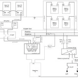
The power inverter gets connected to the batteries as well, but its only function is to convert 12-volt DC battery power into 120-volt AC. Here is how the inverter is wired to the battery bank:
Feel free to download this PDF file for your reference.
Types of RV wiring services
Many RV parks and campgrounds provide electricity service for RVs and you want to plug it into a receptacle that corresponds to your specific wiring type. The most common RV wiring services are:
- 20 amp. Smaller campers and trailers.
- 30-amp. Medium size RVs.
- 50-amp. Larger size RVs with 2 A/C units.
20-amp RV Service
A 20-amp power receptacle resembles a regular household socket and provides 20-amp power at 120 volts:
It is the same type of outlet that you find in your house:
From 20-amp outlet you will get 2,400-watt service:
20 amps x 120 volts = 2,400 watts
If you are not lucky and they only have 15-amp service, you will get a whopping 1,800 watts of power! In this case, use your electrical devices wisely and one by one.
30-amp RV Service
The majority of small and mid-size RVs have 120-volt 30-amp electrical services. If you have a three-prong plug that looks like this:
…find an outlet on your shore power pedestal that looks like this:
This service will supply you with more power than 20-amp service, but it still is not powerful enough to accommodate surge levels of large appliances (like A/C) or many devices used at the same time. So, how much power do you exactly get?
30-amps x 120-volts = 3,600 watts
This means that surpassing the total 3,600 watt capacity in your RV at any time, will most certainly trip the 30-amp breaker! Watch your wattage use and make sure you don’t use the microwave, coffee maker, hairdryer, space heater, and your TV at EXACTLY the same time!
What happens if only a 20-amp service is available at your campsite? You can acquire this wonderful Camco adaptor (paid link):

And watch your power intake even MORE CAREFULLY…
50-amp RV Service
Many larger RV parks have a 50-amp power outlet at your service! If your plug looks like this (with 4 prongs):
… then you have a 50-amp electrical service and need an outlet that looks like this:
This service includes 12,000 watts of power which can be used to power quite large devices like an air conditioner. How did I get this number when there is only 50-amp of power?
This particular service provides two 120-volt hot wires and if you multiply them by 50, you will get the following number:
(50+50) x 120 volts = 12,000 watts
What if you have 50-amp electrical service and only a 30-amp outlet available? NO problem, dog-bone adaptors like this one sold on Amazon (paid link) can help you out here! Woof!

The only problem in this situation is that you will NOT get your normal 12,000 watts service, but only 3,600 watts that 30-amp power supply offers.
Battery bank
The last, but not least important element of your RV’s electrical system is a battery! It is commonly referred to as a “house battery” and it is typically 12 volts.
Lead-acid batteries are the most popular batteries that RVers use, but lithium-ion batteries are gaining more approval now in the RV world. Lithium-ion batteries outlast traditional lead-acid batteries, they are more durable and their life expectancy is a lot longer.
These batteries are initially more expensive, but when you consider how long they last and how much power they provide, they may be worth giving a shot! Lithium-ion deep cycle 200AH battery (paid link) is a perfect choice for any RVer:

How do batteries get charged? Here are some wiring schematics for you.
Generator and shore power
They can be charged from 120-volt shore power or a generator:
This is a PDF file of the above schematics and another one for wiring (PDF) .
Let’s add some solar panels!
You can also add a photovoltaic system (or solar panels) to the setup and you get an ultimate power machine in your RV!
Here is the schematic PFD diagram and wiring PDF diagram.
Legal Disclaimer
Leave a reply cancel reply.
Your email address will not be published. Required fields are marked *
Save my name, email, and website in this browser for the next time I comment.
Automated page speed optimizations for fast site performance
Interactive RV Wiring Diagram: Perfect For RVs, Campervan Conversions, Skoolies, Travel Trailers & Motorhomes
Everything you need for a fully customized rv wiring diagram & design.
Introducing the Interactive RV Wiring Diagram – the ultimate tool for designing electrical systems for RVs, campervan conversions, skoolies, travel trailers & motorhomes.
Designed to provide a comprehensive and efficient solution to the complexities of the wiring systems in campers.
Automatically Create Your Bespoke RV Wiring Diagram
Includes 110v & 240v, solar, B2B, batteries, inverters, 12v, 24v & 48v systems, wire gauges in AWG & mm² & much more!
All-In-One Interactive RV Wiring Diagram Features
- Interactive PDF : With our user-friendly PDF, you can easily navigate through the wiring system of your RV at your convenience.
- Detailed Schematics : Our product provides a detailed wiring schematic for each component, ensuring that you have all the information you need at your fingertips.
- Customizable : With our product, you can customize your wiring diagrams to fit your specific needs.
- Printable : The PDF wiring diagram is a full colour, high resolution image and can be printed up to 91 x 67 cm (34.9 x 26.56 in).
✅ Choose shore power hook up for 110-130v OR 220-240v mains supply.
✅ Calculates how much power your solar panels can produce wherever you are in the world, year-round!
✅ Tells you if you have enough solar to provide all your power needs and if not, exactly what the shortage is in amp hours, so you can compensate by charging while you drive, shore power or extra battery capacity.
✅ 12v, 24v AND 48v battery banks supported.
✅ Calculates battery bank size for Lithium, AGM AND Gel.
✅ Calculates the minimum size inverter needed, without limitations.
✅ Select a combined inverter charger or a separate inverter and battery charger (converter).
✅ Calculates alternator charging B2B size.
✅ Enter your circuit lengths in metres OR feet.
✅ Automatically calculates wire gauges in either AWG OR mm².
✅ Every component is customizable when you want to override the calculated minimum sizes.
✅ One size fits all! Use the Interactive RV Wiring Diagram regardless of what size system you have.
Calculate & Customize Your Camper’s Entire Electrical System
Designing the perfect RV electrical system for your camper just got easier with the Interactive RV Wiring Diagram.
Our powerful tool allows you to effortlessly calculate the ideal solar, battery, wire gauge, fuse, switch, and relay sizes needed for your unique needs – no more guessing required!
With just a few simple details, our built-in calculator will size your entire electrical system and generate a personalized wiring diagram, making your installation process faster and hassle-free.
Plus, our customizable options allow you to tailor each component to your specific needs, ensuring a perfect fit.
Say goodbye to confusing and complicated electrical systems, and say hello to the stress-free and efficient solution provided by the Interactive RV Wiring Diagram.
Start planning your perfect electrical system today!

Audit Your Existing System & Upgrade Your Design
If you’re experiencing trouble with your RV’s electrical setup, the Interactive RV Wiring Diagram is the perfect solution.
It’s designed to help you audit your RV’s electrical system easily.
Visualize your existing setup, identify issues and discprenecies with the existing system size versus the recommended set up , and find solutions to optimize your RV’s power and ensure the most reliable travel experience.
Whether you think your battery bank isn’t big enough, the solar panels are inefficient or your inverter is struggling with overloaded circuits, the interactive RV wiring diagram has got you covered.
Our diagram comes equipped with innovative tools that allow you to customize and visualize the best power setup for your RV.
It simplifies the entire audit process, providing you with a clear assessment of your RV’s electrical system.
From overloaded circuits to underpowered inverters and usage limits, everything you need to optimize your RV’s electrical system is at your fingertips.
The interactive RV wiring diagram is the perfect solution to any electrical woes that you may be experiencing with your RV.
Knowing exactly which components are compatible with your RV’s electrical system will help you avoid costly mistakes down the road.
With the Interactive RV Wiring Diagram, you can be sure you’re buying, installing, and operating the right components for your RV’s electrical system, ensuring maximum reliability and efficiency.
By taking control of your RV’s electrical system, you’re sure to save money while ensuring efficient and reliable travels.
Join the growing list of RV travelers who have taken control of their electrical systems with our innovative Interactive RV Wiring Diagram.
What You Will Get

One electronic copy of the 27 page Interactive RV Wiring Diagram. This is an interactive pdf file.
You need Acrobat Reader on a laptop or desktop to fully utilise the interactive wiring diagram and in-built calculator.
The pdf won’t work with an internet browser or preview apps such as Apple Preview.
If you experience any difficulties, make sure that JavaScript is enabled in Acrobat Reader. You can set it by following these steps: Edit > Preferences > JavaScript > Enable Acrobat JavaScript.
Acrobat Reader will not request a password to open this PDF, unless you attempt to edit the source file. For hassle free access, make sure you use Acrobat Reader and not PDF editing software.
The download link is received immediately after the transaction is complete.
You can print copies of your wiring diagram in full colour, high resolution image and can be printed up to 91 x 67 cm (34.9 x 26.56 in).
Buy Your Interactive RV Wiring Diagram Now
Lots of educational material.
When designing your RV electrical system, we understand that knowledge is power. That’s why, in addition to our Interactive RV Wiring Diagram, we offer additional educational material through our Campervan Electrics Handbook , our website and YouTube channel .
Campervan Electrics Handbook
The Campervan Electrics Handbook provides a step-by-step guide to designing and setting up a functional electrical system.
It covers major components, circuits, battery technologies, charging methods, sizing components, conversion of AC to DC, installation, safety, and troubleshooting.
Readers will learn how to calculate their electrical usage and choose the best battery type, and will gain knowledge on wiring, fuses, busbars and breakers.

Everything you need to know about campervan electrics. Now available in ebook and paperback!
Learn how to design, size, install and troubleshoot your camper’s electrical system.
Mowgli Adventures Website
Our website is home to a wealth of informative articles, providing in-depth knowledge on all things related to electrical sytems for RVs, campervan conversions, skoolies, travel trailers & motorhomes.
From simple how-to guides to more advanced electrical principles, our site covers topics to suit camper enthusiasts of all skill levels.
Mowgli Adventures YouTube Channel
If you prefer a more visual learning experience, check out our YouTube channel.
We regularly upload informative videos that cover everything from product reviews to step-by-step guides for electrical installations.
Our videos are easy to follow and designed to help you feel confident tackling any electrical project on your camper.
We take pride in providing our community with the best possible resources for their camper electrics needs.
Community & Support
Need help & advice with your camper electrical setup?
Our book, website and YouTube channel are just some of the additional educational materials that we offer alongside our Interactive RV Wiring Diagram.
We don’t just provide top-notch resources for your camper electrical needs. We foster a community of like-minded individuals who share your passion for camper living.
Our page is more than just a resource hub – it’s a place where RV enthusiasts gather to share their experiences, knowledge, and expertise.
Whether you’re a seasoned pro or a novice in the world of RV camper electrics, you’ll find a welcoming and supportive community here.
From advice about common electrical issues to innovative DIY solutions, our page is the go-to place for all your RV electrical needs. With our friendly and knowledgeable members, no question goes unanswered.
Join us today and become part of a community that shares your love of RV living.
Together, let’s create a space where we can share our experiences, learn from each other, and build a genuine support group.
3 thoughts on “Interactive RV Wiring Diagram: Perfect For RVs, Campervan Conversions, Skoolies, Travel Trailers & Motorhomes”
I have a 1994 Coronado what are the wires and diagram to put it back together
I have a 1999 newn hitchhiker 5th wheel the shore power cord and wiring was removed, would like to hook it all back up. I need a little help with what wires go where. I have looked for a wiring/fuse box diragram but have had no luck.
I’m looking for a schematic for 2000 fleetwood bounder coach for the water pump system it has 3 switches
Comments are closed.
© 2024 mowgli adventures
Privacy Policy | Terms Of Service | Sitemap
Part of Mowgli Adventures Media Ltd. Registered in England and Wales. Company Number 13558893
Where You Make It
Understanding Your RV Electrical System
Hey! This site is reader-supported and we earn commissions if you purchase products from retailers after clicking on a link from our site.
As a rule, your RV will have two separate electrical systems that draw different voltages as well as two different types of current. Just as a “sticks and bricks” home is based upon 110/120v power system, so is your RV.
However, because your mobile home away from home is also dependent upon using a 12v system and in this article, we’ll take a look at some of the components that make up your system and what they are meant to do.
We’ll look at:
- Different power sources you can use
- Each component of your electrical system
- Proper setup of wiring, breakers, and fuses
- Where you should include outlets
- Other pro tips and watch outs
What are my sources of electrical power when traveling in my RV?
Unless you’re special ordering a manufactured motorhome or towable RV, the two basic sources of electricity in a manufactured RV will be shore power and house batteries which I will explain below as well as some alternative sources for power such as solar power and generators.
What is shore power?
Although this term is commonly used when referencing boats or marine vessels when docked at a marina and plugging their electrical system into the main grid used by the marina, the term is also used when referring to RVs being plugged into a main power grid supplied by a campground or an electrical circuit at someone’s home or business.

Most manufactured motorhomes and campers will have an electrical system and long power cord that allows you to plug into shore power , although some older models may be missing this feature especially if your RV was built before 1970.
Should you be doing a custom build or restoration of an RV, installing a shore power can be very simple to more complicated depending upon how you want your power supply to operate and the number of items you wish to power.
For example, you may have a small van that you have converted to an RV and it is wired with 12v lights and RV refrigerator, but you want to add a 110v line because you want to power a laptop computer, charge your camera batteries or watch some television.

Adding one or two outlets like this can be done easily by simply installing a weather appropriate inlet on the side of your van that is wired directly to those indoor outlets on a single line. This works well for people that have a limited need of shore power and you only need a good outdoor 110v extension cord to run from the power box or outdoor outlet to your inlet.
However, the larger your RV, the greater your shore power needs will be too. Generally, class A motorhomes are equipped with a 50-amp power plug and class C may have either a 50-amp or 30-amp power plug. Class B motorhomes are usually 30-amp as are smaller campers. Remember, the more bells and whistles you have on your RV determines the amount of amperage you will need.
Another thing to keep in mind when RVing is that smaller and older campgrounds may not have the electrical outlets that your rig requires. It’s not unusual to find many campgrounds are only supplied with 30-amp outlets. To avoid this happening to you, I would recommend that you purchase an adapter that takes your 50-amp power supply down to a 30-amp supply.
The downside of this, however, is that you will need to be especially mindful of the amount of electricity you are drawing at any given time. When your system is designed to be running efficiently at 50-amps and you lower the intake to a 30-amp draw while still trying to run as many appliances, electronics, and air conditioning then it is likely you will blow a fuse or pop a breaker.
What are house batteries?
Most RVs will have at least one deep cycle trailer battery that is used to supply power to 12v outlets and appliances such as exhaust fans, carbon monoxide detectors , RV style refrigerators, and some lighting. Usually, the bigger the RV, the more batteries you are likely to have.

- UB121000 SLA is a 12V 100AH Group 30H Sealed Lead Acid (SLA) Maintenance Free Rechargeable...
- The spill-proof SLA/AGM battery features high discharge rate, wide operating temperatures, long life...
- Rechargeable battery that can be mounted in any position, resists shock and vibration. Long lasting...
Last update on 2024-05-08 / Affiliate links / Images from Amazon Product Advertising API
Keep in mind however, that things like an RV refrigerator can drain your battery or battery bank rather quickly so you need to keep an eye on that power consumption by checking your battery monitor often.
You should also be mindful of the type of battery needed for your house RV battery and that it’s best to use a deep cycle battery that can handle heavy draws of power as well as being constantly drained and charged which will take a toll over time with cheaper RV batteries not designed for that type of use.
House RV batteries can be charged by various sources but are most often charged when you are plugged into shore power, while you are driving down the road by your engine components or a solar system. You can also use a deep cycle battery charger to power it up.
What is a battery monitor?
Battery monitors are used to keep track of the amount of power coming into your RV and the amount you are drawing from your battery or battery banks at any given time. Generally, the larger your trailer or motorhome, the more advanced your monitor will be.
For example, you may have solar panels that are adding power during the day and you may want to periodically check the amount of power coming into your RV during these times. The same can be said about usage during the night when you are more likely to be drawing from your RV batteries instead of charging them.

- Test range: Voltage: DC 6.5~100V; Current: 0~100A; Power: 0~10kW; Energy: 0~9999kWh
- Store energy data when power off (can be reset to 0). The blue backlight can be turned on/off...
- With overload alarm function (If active power is larger than threshold, backlight and power value...
Last update on 2024-05-07 / Affiliate links / Images from Amazon Product Advertising API
Depending upon how many functions you need your battery bank to perform and access to the data when it is working, you can decide on the type of monitor you will need. Manufactured RVs with house batteries will always have a battery monitor located inside and usually in the same proximity as your fuse boxes.
However, if you are upgrading or designing your own electrical system you may need to replace or determine the best monitor that works for you. As with most electronics these days, the complexities of these monitors vary any many of them can even be accessed online or via cell phone applications when you are away from your rig.
What are alternative methods for supplying my RV with power?
Many class A motorhomes and higher end campers such as 5 th wheels come with the option of including a generator when you order or purchase them. The advantages to having a generator that is installed on your RV from the manufacturer is that it is easily turned on by activating a switch inside your RV and that it is fueled by an onboard supply.
By this I mean that many class A motorhomes have their generator designed to burn the same fuel as the engine requires and this eliminates the need to refuel them separately as you travel.
Another advantage to having a factory installed generator for your RV is that it will be installed in a well-insulated yet well ventilated area of your rig. It’s also likely to be quieter and less disturbing to those camping near you.
However, factory installed generators can come with numerous disadvantages as well. Probably the major deterrent for most people is the added cost when they are initially exploring the idea of ordering and purchasing a new RV .
These type of systems are very expensive and come with numerous added components that through travel and frequent motion, are likely to fail more quickly than adding an aftermarket generator to one of your storage bays and setting it up for use outside and away from your RV as you boondock or visit dispersed camping sites with little or no power resources.

- This popular model can operate a wide variety of appliances, making it perfect for portable use at...
- So quiet, your neighbors will thank you. The EU2200i operates at 48 to 57 dBA, which is less noise...
- Add a second EU2200i for additional power. Two identical models can be paralleled with an optional...
While I’m not a huge fan of using gasoline or propane portable generators as a long-term source of electrical power, they do come in handy for short stays in an area where shore power is scarce or non-existent.
For short-term RVers and those looking to fish or hunt in remote areas, I would recommend having a good gasoline generator with you that will run continuously for longer periods of time on the fuel supplied to it.
Personally, I have always had a portable generator that uses propane and while more expensive to initially purchase, the safety I feel I gained by not carrying around filled gasoline cans was far worth the extra cost. I also don’t have any issues boarding a ferry boat.
Remember, when choosing a generator, always consider the fuel needed to operate your system where you are traveling. There are places in the most northern parts of the American continent where there is no gasoline and propane tanks are the main source of fuel.
On the other hand, there are several long stretches through Mexico and many Central American countries where you won’t find access to propane.
That said, generators are always a good option, but keep in mind that most of them are loud and gasoline or diesel fuel generators produce exhaust that smells bad. No one wants to be in a beautiful location and listen to the drone of a fossil fuel fired generator a few hundred feet away or worse yet, right next door.
In short, if you choose to use a generator, use it sparingly and respect the wildlife and those that may be camped near you.
Solar power
Frankly, my preferred method of alternative power is solar based, and I am amazed by the amount of technology and economic theory that has come with this source of power over the last few decades. I grew up in an era where solar power was just being developed. Its components were large, and it was cost prohibitive for most people that were interested in incorporating it into their lives.

Today, electronic components have become more advanced, solar cells are much smaller than when first developed and the prices have dropped considerably since they were first developed. I love my solar electrical system and it literally has allowed me to stay in comfort at places where I couldn’t have stayed just 10-20 years ago.
For a better understanding on how to install a solar electrical system on your RV, please take a look at my colleague Lindsey’s article where she give you an excellent tutorial about installing solar power on her RV. Also, take a look at our picks for the best RV solar panels .

- 【Efficient Performance】The 200W Solar Panel Starter Kit will produce an average of 1000Wh of...
- 【Solid Quality】Advanced encapsulation material with multi-layered sheet laminations protects...
- 【Smart Function】The Wanderer PWM Charge Controller is compatible with four different types of...
I have an inverter and a converter in my RV electrical system. AC vs DC
No, an rv power converter is used when you are hooked up to shore power at a campground and it converts your 110 volt AC power down to 12 volt DC power to keep your house batteries fully charged.
On the other hand, an inverter is used when you are not on shore power and want to use 110v for something like a coffee maker, microwave or television and this inverts your power from 12v DC power to 110v AC power. You can read my article on how to install an inverter for more info.
Proper setup for wiring, breakers, and fuses
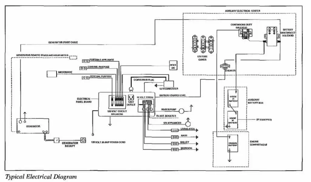
As I said earlier, RV electrical systems can be simple or complicated depending upon how you want your system to perform. In this diagram you’ll see that this is the most common RV electrical set-up and the basic type most often installed by manufacturers.
Normally, when you plug your RV into shore power, the current flows to your 110v A/C breaker panel where it is then dispersed to your RV electrical outlets for plugging in small appliances, 110v lights or electronics. It also will send current for some appliances such as larger exhaust fans or water heaters that are hard wired directly.
The breaker panel will also send a 110v current into the charge converter that I explained earlier. Remember, the converter reduces that 110v to 12v where it is stored and recharges your house batteries, part of your electrical system.
Once here, the 12v current will then supply electricity to a fuse box that works exactly as the larger breaker box that your shore power flows into initially. Smaller 12v light fixtures, your water pump, and some electronic power or chargers can also utilize your 12v power supply as well as some outdoor lighting and even your furnace fan motor.
You should also take note that in this schematic, they included a box that represents power being supplied to your house battery/batteries. This is the electric current being supplied when you are not using shore power but are instead driving down the road or even idling your motorhome engine.
Almost every motorhome has their engine’s alternator designed to supply current to their house batteries, and many towable RVs are wired through their tow vehicle and camper connections that supply power to your camper’s electric brakes and lights when driving while also recharging your RV batteries.
Where should I put my power outlets?
Most often, this question will have no direct or specific answer. It’s really all about what you want the design of your RV to be. Simply put, where do you think the power supply outlets should be based upon your needs?
For example, if you have no reason to have an outlet next to your bathroom sink, then don’t design one into your plan. Personally, I recommend having two 110v outlets near your cooking and food storage area to supply 110v to a dual powered refrigerator as well as supplying power to a coffee maker, microwave, toaster or any other item you may want to use when connected to shore power.
I would also make sure that I had an outlet or two wired to my living area and/or bedroom, so I could access my computer, watch my TV or listen to some of my favorite music while traveling. That said, I would include 2-3 outdoor outlets on my RV to cover security lighting as well as lighting for safety.
Final thoughts
In an upcoming article, I’ll be sharing some thoughts on how to troubleshoot RV’s electrical system as well as making some repairs for common problems you may encounter with that system while you travel. One I published recently is a guide on what to do when RV battery won’t charge . Until then folks, thanks for reading and as always, I hope to see you out there someday.
For other electrical work, read these related articles.
- Best RV surge protectors
- Best battery for travel trailers
- Best trailer brake controller
- Best RV monitor panels
- How to start your generator
Related Articles:

Born and raised in Michigan, contributing writer Brian C. Noell is a retired hospitality industry professional that now works remotely as a visual artist, writer and photographer as he travels around the United States in an RV with his dog Lizzy, an eighty pound Appenzeller hound dog.


RV electrical system: basics, design, problems and troubleshooting

- BEGINNERS GUIDE
G. Yoganand
Are you interested in knowing how travel trailer electrical system works? Well, then in this post i am hopefully going to be able to provide you with answers to some of the most-pressing questions. Lets try to understand RV electrical schematic, designs and common issues and solutions.
This way you should be able to get your travel trailer electrical system set up pretty well. Or At least have a good idea about what you should be doing and what you should be looking for which will make your life easier. This is a helpful RV wiring guide for dummies or beginners.
How do the electricals work in a travel trailer?
Honestly, the electrics inside of a travel trailer are not much different to your home. You will have a main ‘feed-in’ point for the electrics i.e. the initial power generator. You then connect this up to everything, and the juice will run through the travel trailer to the various lights and plug locations.
It is rather simple. The only difference between your home and the travel trailer is that you will have to connect the travel trailer up to that initial power supply on your own.
Basics of electrical components in an RV
Honestly, when it comes to the electrical components in an RV, you don’t really need to remember all that much.What you do need to know is that there are two different power systems in your RV.
You will have the 110-Volt system that will power all of those appliances, and then you have the 12-volt system.
The purpose of the 12-volt system is to keep the digital instruments in your RV running, just like a standard car. There is no overlap between the systems. The 110-volt system will run off a generator or shore power supply, while the 12-volt will be run off of a standard battery, just like a normal car.
It is imperative to think about the amount of wattage the 110-volt system will draw at once. This will ensure that you are able to feed the right amount of power into the RV. In fact, most of the things you need to think about when it comes to how travel trailer electrical system works will be related to wattage.
You don’t need to know much beyond that, as the bulk of the wiring will be done for you. In the vast majority of cases, you just need to plug in the cable that connects from the power supply to your travel trailer, and you are good.
Inverter and Converter : The only other components you will need to know about will be the inverter and converter. It is the former you will encounter the most, as it is the inverter which will convert DC current to AC. It is rare that you will need to convert AC to DC, but that is what the converter will do for you.
How does an RV or Travel Trailer Get Power?
Power for an RV or travel trailer doesn’t just come out of nowhere. You will need to have that initial power supply feeding into the system. We will look at the various power supplies in a short while. This power supply will be connected by via a heavy-duty cable. It is really a quick and easy process, and if you do it once, then you are always going to remember how to do it.
Different power sources used in a Travel Trailer
When it comes to power sources for a travel trailer, you have a few different options. If you are staying on a campsite, which most people will be, then you will be able to pay a little extra to have an electrical hookup that you can use.
Campsite Shore power : There may be fees for the amount of power that you consume. This is, essentially, like being wired into the ‘mains’ supply of a household. The power comes from the hookup and is fed directly into your travel trailer. It is a really simple method. You don’t need to think much beyond connecting up a wire and letting the system do the work for you.
Generator : If you are planning to be out on the road a bit, then it is likely that you will want to invest in a generator of some description. The generator can be loaded with fuel (normally gasoline or diesel) and it is switched on.
The fuel is burned, which in turn causes a reaction that generates electricity. It is basically like a mini-power plant. Generators can be heavy. But they work, and they can provide you with predictable power no matter where you are located.
Solar : The other option is to invest in some solar panels. The solar panels will charge a battery, which, in turn, will provide power to the rest of the travel trailer. These systems can be expensive. They can save money in the long run as you won’t need to worry about filling the system up with fuel.
It also means that you do not have to pay extra fees when staying on a campsite. Obviously, the solar panels can be used no matter where you are. This means that it may be one of the better options when you are out there on the road.
Battery : A DC 12 V battery can be source of power for your travel trailer. It can howevere may not able to run most of your electrical or elctronics items. But, its a necessary source of power to run smaller appliances.
30 amp vs 50 amp hookup in RV
There will be two types of electrical hookup for your RV. You will have either 30-amp or 50-amp. There are a few differences to them. For example:
The 30-amp will look much like a standard plug. There are three different prongs. One of these is neutral, one is ground, and the other is 110-volt live. The 50-amp will have four prongs. There are a neutral and a ground wire. There will be two 110-volt live wires.
Watts : The maximum number of watts that a 30-amp hookup can deal with is 3,600 watts. It can’t deal with anything more as it simply can’t pump out the power that is needed. Alternatively, the 50-amp will be able to provide 12,000 watts.
As you can probably guess; the 30-amp electrical hookup is going to be better for those RVs that have lower power consumption requirements. While the 50-amp will be more ideal for those larger appliances. You may or may not have both options available to you in your RV and on the campsites that you visit.
How much power or electricity do I need for my travel trailer
How much power you will need in your travel trailer will be completely dependent on what you are actually planning to power within your travel trailer. Perhaps your best bet will be to go through your travel trailer and add up the wattage of everything inside.
This should give you a rough overview of your power requirements. You will then want to add a small amount on top of this. This is because when you turn on an appliance or other electrical item on, it will require a slightly higher power load, just to boot it up. It will then reset.
If you don’t want to stagger turning on the appliances wired up to your trailer electrical system, then this is something that you are going to need to bear in mind.
Do bear in mind that the higher your power requirements, the heavier the generator you will need if you are bringing one along with you. Most people will not have every single appliance running in their trailer at once, so you probably do not need to go overboard with power. No sense buying a 5000 Watt generator if you are planning to only ever use 2000 Watts at once, right?
How does a converter work in a camper?
It is rare that you will need to use a converter in a camper, although they are useful to have, particularly if you are using a lot of smaller electrical items. This is because these smaller electrical items require DC power, and most hookups will be AC.
You will need a way to convert this AC current into DC current, or you run the risk of damaging your small electrical items e.g. phones, and some of the netbook-style laptops.
The reason why they tend not to see as much use as an inverter is the fact that most electrical items come complete with a charger that does basically the same job anyway. So, a converter is always useful to have, but it isn’t going to be 100% necessary.
Common travel trailer electrical problems and their troubleshooting
There are several issues which can be resolved by yourself should they occur in your travel trailer. Perhaps the simplest problem is the blowing of a fuse. Incidentally, most people don’t ever seem to realize that the power not turn on at all (or randomly turning off never to go back on again) is down to a blown fuse. Always carry a stash with you. This way you always have something to hand to replace the fuse.
If you find that the power is going when you turn on certain appliances, then you may want to reduce the load on the power supply. It is likely that you will be drawing a lot more wattage than the system is set-up to handle.
Other issues may be down to wires that are not grounded touching metal. This can cause a short circuit, which can cause the power to go completely, or not enough power to be spread throughout the system. This is easy to diagnose. Unplug everything. Replace the cable that feeds the travel trailer.
This information should help you to resolve the vast majority of issues that may occur in a travel trailer.
Using solar in travel trailer
If you want to save as much money on power as possible, then you may want to look into a solar generator, or solar panels. Throughout the day (it doesn’t necessarily have to be very hot and sunny!), the solar panels will absorb the rays from the sun.
This does a bit of scientific wizardry, and will charge batteries as it does so. These batteries then provide the power to where you need it. So, basically, solar panels will be charging batteries to store energy.
Hooking up solar power to your travel trailer is as easy as any other type of electrical hookup. Just connect it up to the main electrical socket for your travel trailer and it will work, that is assuming that the batteries are charged. The initial charge on the batteries may take a little while.
Is Solar reliable option?
Do bear in mind that solar panels will not always provide reliable power. You are at the whim of the sun and your batteries, and they are not going to charge overnight. This means that you may need to be a little bit more conservative with your power. Particularly if days are pretty cloudy as the batteries may not get the full amount of juice that they need, which could have an impact on the amount of power you can produce. If you are in one of the sunnier climates, then solar energy is fantastic.
Yes, it will cost a little bit more to buy the panel initially. There is little that can go wrong, and you will essentially be generating ‘free’ energy, although you may want to have a backup just in case the solar panel is unable to deliver all of your energy needs.
The good thing is that any backup power supply you need doesn’t have to be too big. Just enough to keep the ‘must haves’ running, like your fridge and freezer.
Obviously, this is not everything that there is to know about how travel trailer electrical system works. But, I do hope that it gives you a decent idea, and points you in the right direction of what you need to get up and running with your power supply.
After all, one of the true joys of having a travel trailer is the fact that you do have the opportunity to have electrical items set up in it if you want. This guide will have hopefully given you a good start there.

You Might Also Like

How To Install AC On Teardrop Camper

9 Tips To Negotiate When Buying A New RV

RV Air conditioner leaking – reasons and solution

Are Pop Up Campers Allowed in National Parks ?
What are you looking for?
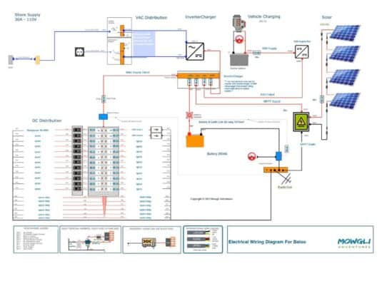
Below are some of our example power systems for camper vans/RVs. The Victron-based systems all have a corresponding blog post, free detailed PDF example wiring diagram, and a corresponding discounted product bundle . Ultimately, you'll probably customize your system to your particular needs and perhaps combine ideas from one or more of the example systems.
- A baseline camper van electrical system that uses lithium batteries with internal battery management systems (BMS) such as a Victron SuperPack, Battleborn, SOK, etc. This is our most affordable and simple system as well as the most DIY friendly.
- A more advanced camper van electrical system that uses Victron Smart lithium batteries with an external BMS and a Cerbo GX for monitoring. This system is a bit more complex and more costly, but adds features and allows for more battery storage in the same physical footprint. If you use the Victron Lynx Smart BMS you can upgrade to a dedicated secondary alternator with a Wakespeed regulator in the future.
- A super powerful (fast-charging) system that uses a dedicated secondary alternator . This system is the most expensive but also the most off-grid capable. We also have a 48-volt version of this system!
- We also have a power system accessories bundle that has all the circuit protection, shore power, distribution, and wiring you'll likely need.
Please consider purchasing your power system equipment from our store . Our bundles offer great pricing (yeah, better than Amazon), free shipping and you'll have access to expert support and you'll be supporting our ability to create more content!
Finally, there are a few things that we don't sell in our store (yet!) that you might need so we keep a list of these products in this Google Sheet of recommended camper van products .
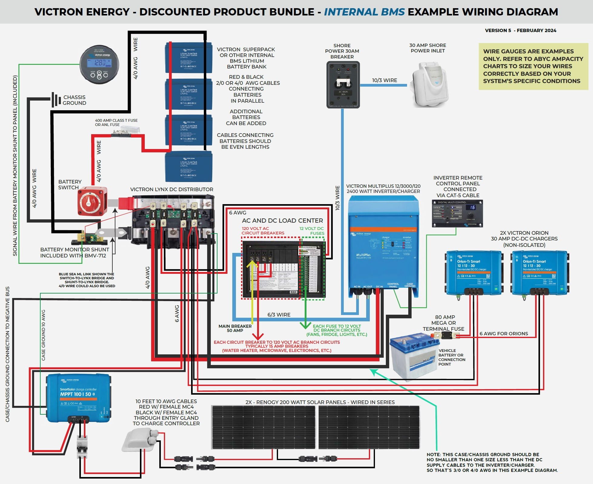
- 400 amp hours of lithium battery storage with built-in BMS
- 400 watts of rooftop solar
- 2400 watt inverter (up to 6000 watts surge) with 120 amp shore power charging capacity
- Integrated 12 volt DC and 120 volt AC load center
- 60 amps of alternator charging when driving/engine is running
- Optional pre-inverter shore power outlets
- Battery monitoring with Bluetooth
It’s super important to realize that there are hundreds of ways of skinning this cat. How awful. We won’t be skinning cats and neither should you. Anyway, the point is that this information should be considered a guide not gospel. You certainly could build out this system exactly as detailed but I would recommend considering your particular needs and then adjusting accordingly.
Also, wire lengths matter. This electrical diagram assumes that there is about a 20′ run from the vehicle battery back to the driver side wheel well where the “primary” electrical system is installed. What I mean by “primary” is most of the stuff you see on the wiring diagram – all the main parts but not the “branch circuits” that power the actual loads in the van like lights and fans, etc. It also assumes all those components are close together – not more than 5 (ish) feet of cable run between them. If your actual setup is different than this you need to adjust the wire gauge (AWG) accordingly. The Blue Sea Circuit Wizard is a great tool for understanding what gauge wire you need. You put in the load in amps, the length of the cable run and how long it will be running in minutes and it will tell you the correct gauge. I favor “over gauging” in general. Wire is pretty inexpensive relative to the other parts. In this wiring diagram I have also over gauged to keep it a bit more simple so that you don’t need so many types/gauges of wires and lugs and so on.
Speaking of wiring … you’ll probably use wire loom to protect your wires when you run them in areas they might be damaged by rubbing against stuff. So, let me introduce you to this “ wire loom insertion tool “. It’s pretty much a game changer.
Why A 50 Amp Breaker?!
With most 2000 or 3000 watt inverters you would match the shore power’s 30 amp inlet on the output side. However, Victron Multiplus inverters have a unique feature -they will actually supplement the utility power coming in from the shore power plug with their inverted power – up to 3000 additional watts. So, if you manage to have enough stuff running in your van to exceed the 30 amp service from the shore power, the inverter would actually fill in the gap instead of tripping the shore power breaker. So, while this is not likely to happen unless you’re running some kind of crazy loads in your rig, it’s important to provide circuit protection and adequate wiring “just in case”. Therefore this wiring diagram calls for a 50 amp breaker downstream from the inverter with 6 AWG wire instead of a more “typical” 30 amp breaker with 10 AWG wire.
Inverter Wattage
If you look closely at the specs of the Victron Multiplus inverters they don’t actually support continuous 2000 or 3000 watts respectively. This isn’t important but it can be a bit confusing because of how they’re named.
The MultiPlus 12/3000/120 outputs 2400 watt continuous output at 77 degrees, 2200 watts at 104 degrees and surge up to 6000 watts.
The MultiPlus 12/2000/80 outputs 1600 watt continuous output at 77 degrees, 1450 watts at 104 degrees and surges up to 4000 watts.
Victron MultiPlus Inverter/Charger Configuation
Once you get your system all wired up you’ll need to configure/program the MultiPlus to, at minimum, work with the batteries you’ve chosen and maybe tweak a few of the other settings. We have another post on how to do that .
A Little Battery Update (June 2021) In addition to the complexity, the other pain point around electrical systems is how expensive they are. In particular, the leading brands of lithium batteries such as the Victron SuperPack batteries we show in our example and other popular brands like Battleborn) are very expensive – about $1,000 per 100 amp hours. It’s a classic sort of “pay for what you get” scenario and there are good reasons to purchase the highest quality components. For example, the are excellent quality, designed to last for many years with 10 year (!) warranties. But, the truth is that not every van build needs the very best batteries and there are well-made alternatives that are just about half the price! In some cases, having more capacity (amp hours of stored energy) may be better than more longevity . You can ask yourself, do I want to run the stuff in my van twice as long for a few years or half as long for a decade?
Anyway, Will Prowse made an excellent video testing out well-built but lower cost lithium batteries that is worth checking out. One example is the SOK 206 amp hour battery that is currently selling on Amazon for $1,029.
Wiring Diagrams
The image below is for quick reference but I recommending downloading the PDF file (below) for much more detail and the ability to print/zoom in.
If you have AC loads that should ONLY be powered by shore (utility) power , (not inverted AC power), you can use the “AC out 2” connections on the MultiPlus inverter/charger which is only “live” when shore power is available. One good example of this would be an AC/DC refrigerator. Many of those will “default” to AC power when it’s available. If you wired up an outlet near your refrigerator that was powered by the inverter, the fridge would switch to that source of power anytime the inverter was on (inverting) which is less energy efficient that it continuing to run off the 12 volt DC power. If, instead you wire up that AC outlet that feeds the refrigerator, it will only run off the AC power when you have shore/utility power.
If You’re Using a Renogy DC-DC Charger Instead of the Victron Orion Units
Unlike some other battery-to-battery charging products that sense voltage and trigger the charging based on that, the Renogy DC to DC charger (or battery-to-battery charger) that I used requires you to connect up a 12 volt positive “signal wire” from the vehicle’s ignition switch so that it only charges from the van (vehicle) battery when the ignition is turned on. Without this ignition trigger on this unit or the voltage sensing on others, the battery-to-battery charger could easily drain the van battery since the battery-to-battery charger would be pulling current without the alternator providing a charge.
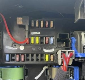
After some research I discovered that some Promaster vans (2016 or newer I think) have a “Upfitter Connector” on the passenger side “pillar” which is that area just behind the passenger seat where the seat belt connects to the van wall. If you remove the black plastic trim at the bottom of this “pillar” you’ll see a white multi-pin connector (photo below). This is the “upfitter connection” that provides a variety of connection points for the Promaster in one spot. This PDF file ( Promaster Upfitter Connector Diagram PDF ) details this connector including what each pin on the connector is/does. Turns out that pin #13 is an “ignition feed” that has 12 volt positive when the ignition switch is on. So, I used this to be the “trigger” for the Renogy DC to DC charger.
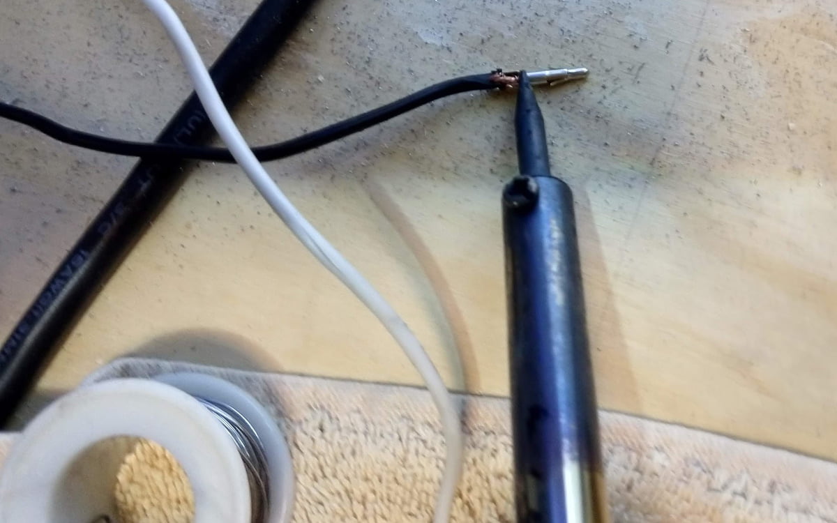
In order to do this, I had to order the correct, “male” version of this connector (part number 1-480710-0) as well as the “pin” itself (part number 350218-1). The way this works is that you solder the correct wire to an empty pin and then insert that pin into the correct position on the connector thus allowing you to access and wire up a variety of things to this upfitter connector. These parts are pretty inexpensive so I bought a few with the expectation that I’d destroy a few figuring out how this all works. I’m glad I did because I did indeed destroy a few experimenting. Ultimately, it’s not difficult but finding the right parts and how they fit together took some time. So hopefully this saves you that time!
The wire coming out of pin #13 on the Upfitter Connector runs back to the rear passenger side wheel well where the primary electrical system is installed and is connected to the Renogy DC to DC charger on a terminal labeled “D+”. Below is a photo of this connection:
Next I had to configure the Renogy DC to DC charger to correctly charge the lithium batteries using the DIP switches pictured above. The manual for this Renogy DC to DC charger is really bad and the section on setting up the DIP switches is complete gibberish. I gave up on it pretty quickly and called into Renogy support. The correct DIP switch settings for charging lithium batteries with the Renogy DC to DC charger is:
- Switch #1: Off
- Switch #2: On
- Switch #3: On
- Switch #4: On
- Switch #5: Off
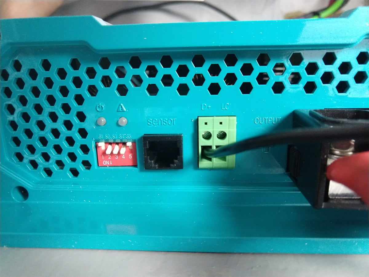
Turning On The LED Lights On The Lynx Distributor
There are LED lights on the Lynx Distributor that indicate if each of the circuits is live (the fuse isn’t blown). They light up green when it’s good and red when it’s not. These lights are normally powered when the Lynx Distributor is paired up with the Victron Lynx Shunt but you don’t need that if you use the “better-for-vanlife” (my opinion) BMV-712 battery monitor (listed above) which has it’s own shunt for monitoring.
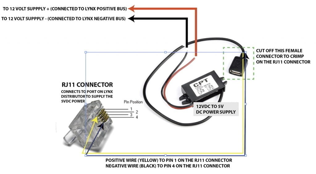
So, if you don’t want to buy that hardware but do want the fancy lights, you can “hack” the lights with a 12 volt DC to 5 volt DC converter and an RJ11 “phone style” connector . This will provide the 5 volt power the LED lights need to fire up. Below is an illustration on how you’d do this – at your own risk, of course .
We Appreciate Your Support!
Sign Up For Our Monthly Newsletter
We strive to make the newsletter worthy of your inbox. It's full of relevant news, featured campsites, DIY build tips, events/meetups and more!
- Mailing List
Interactive Wiring Diagram for DIY CamperVan, Skoolie, Small RV, etc.
Here is an interactive version of our wiring diagram for DIY campervan conversion, skoolie, RV, etc. You can click on products to learn more. To see a list of all the features available on our downloadable PDF wiring diagram, head to faroutride.com/wiring-diagram .
Optimized for off-the-grid / energy efficiency

KEY FEATURE:
The inverter and shore power are provided by two separate devices. No transfer switch to bypass the inverter when plugged to shore power.
MORE FEATURES:
- BATTERY BANK : 100Ah and up (one or more batteries)
- SOLAR : None or up to 700W
- ALTERNATOR : None or up to 60A
- SHORE : None or up to 80A DC
- AC IN: 15A (normal house outlet)
- INVERTER: None, 1000W, 1500W or 2000W
- TRANSFER SWITCH: None
- 120V AC Distribution Panel: None (loads are connected directly to the inverter)
CHOOSE THIS DIAGRAM IF:
- Your build has modest 120V needs (no device above 1,650W).
- You’re mostly off-the-grid (occasionally plug into shore power).
- You’re tracking your budget. Some components (bus bars, cables, switch, fuses,etc.) in this diagram are cheaper (and smaller) because they’re rated for lower current.
- Maybe you don’t need shore power or inverter at all?
Optimized for high-power devices (induction cooktop, microwave, etc.)

The inverter, shore power and transfer switch are combined into a single device (Victron Multiplus).
- BATTERY BANK: 200Ah and up (two or more batteries)
- SHORE : up to 120A DC
- AC IN : 30A (campground hookup) or 15A (normal house outlet, via adapter)
- INVERTER : 2000W or 3000W
- TRANSFER SWITCH : Yes (automatically bypass inverter when plugged into shore)
- 120V AC Distribution Panel : Yes (each load is protected by an appropriate breaker)
- Your build includes any high-power device: air conditioning, induction cooktop, electric water heater, electric space heater, etc.
- You frequently plug into shore power (serviced campgrounds).
- You simply prefer an inverter/charger (Victron) instead of a separate inverter & battery charger.
Just getting started? You might want to read our Electrical System Guide first, and work your way up!
DIY Van Electrical Guide: Build Your Knowledge
WE’RE JUST GETTING STARTED.

Stay in touch!
JOIN 40,000+ FOLLOWERS VIA FACEBOOK, INSTAGRAM OR YOUTUBE:
Support us on Patreon | Join our mailing list
NICE TO MEET YOU.

Hello! We’re Isabelle and Antoine 🙂 In 2017, we sold our house (and everything in it), quit our engineering careers, and moved into our self-built campervan. Every day is an opportunity for a new adventure... We’re chasing our dreams, and hopefully it inspires others to do the same!
Heads Up: Exclusive Deals!
Thanks to all of you, we managed to negociate group discount on these. Strength in numbers!
- Scopema Swivels and Cabbunk Bund Beds : 5% OFF with coupon code "FarOutRide".
- VanMadeGear Insulated Window Covers : 5% OFF with coupon code "faroutride5percent".
- Van Scans and 3D Models : 10% OFF Scans (code "FarOutRide") and 5% OFF 3D Models (code "FarOutModel").
- Bay Marine Supply : We're trying, let's see how it goes!
- Lolo Racks : $40 OFF with coupon code "FarOutRide".
Wiring Fleetwood RV Electrical Schematic (Diagram Download)
Working on wiring is secure as long as the proper safety measures are taken.
You shouldn’t have any trouble changing any wires on your RV or its appliances, etc., as long as you have a wiring schematic.
However, there are still hazards, therefore it is better to leave this duty to the experts.
For this model of RV, there are several places where you may acquire wiring or electrical schematics.
Remember that there are many models, floor designs, and electrical layouts to take into consideration.
This may not be a set-up that works for everyone.
Continue reading our post to find out more about this subject and how to get your schematic.
Although we are unable to connect to every model’s schematic, this article will point you in the correct direction.
Spend some time finding the appropriate way.
What Exactly Is A Wiring Diagram?
It is sometimes referred to as a wiring diagram, and both terms are equally accurate.
A schematic or wiring diagram is an abstract representation of how the cables appear inside your RV.
These schematics are produced by all manufacturers, including Fleetwood, to aid electricians in knowing where to look and what cables link to what.
These designs may be challenging to understand and may resemble a labyrinth or jigsaw puzzle to the inexperienced eye.
It is preferable to employ an electrician if you lack the necessary training.
The improper cables may lead to several additional issues that will cost more to fix or replace.
Even if you have access to a wiring diagram, be aware of your limits and leave any electrical issues in the hands of the professionals.
By downloading and printing the appropriate wiring schematic for your Fleetwood RV or travel trailer type, you can assist the experts.
Remember that not all Fleetwood models are covered by the schematics that are available here as a picture or for download.
For your specific size and type of Fleetwood RV or travel trailer, you may need to look a bit harder.
Fleetwood RV Electrical Wiring Diagram
Two straightforward wiring diagrams will be included in this section.
They originate from this website.
You may find some other, far more sophisticated schematics on that page.
They address several elements of a basic Fleetwood model.
All of the diagrams on that website seem to be available for download.
Each one includes the source for the diagrams as well as download instructions.
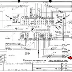
It seems that this schematic is for a 1995 Fleetwood Southwind RV.
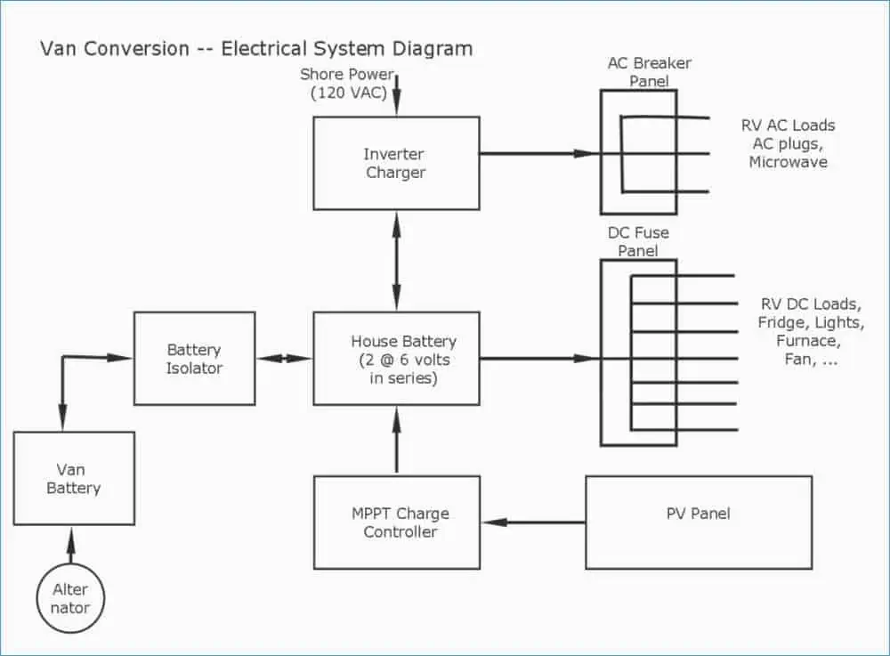
2. Van conversion
Although they are older models, there are still a lot of them on the road today.
Click on that link to obtain the download instructions.
Those looking to restore their homes may need this diagram.
We will provide some links to more recent models in the section that follows.
Remember that you can always get in touch with Fleetwood to see if they have schematics for the specific type of RV you have and can send them to you.
Fleetwood Motorhome Wiring Diagram Download
You may access a 2020 Fleetwood model at the first link, which seems to be for the chassis alone.
Even though we have made an attempt to look for more recent models, the older wiring schematics still appear in our search results.
Here are a few links to vintage Fleetwood RV models that could be useful to certain owners.
Check the picture results after doing the search to determine whether the image you need is among the many that are shown.
We spotted quite a few, but the pictures were too little to include on this page.
We particularly appreciate the final link in this list since it includes a graphic of a particular RV model and shows where the cables connect to the amenities and appliances that are incorporated into that kind of RV.
This last link provides a collection of illustrations and images that highlight various features of a certain Fleetwood model’s electrical system.
Fortunately, you can see and even download all of these wiring schematics for free.
Tip for Wiring Diagrams
- Keep in mind that travel trailers and RVs have two different electrical systems when you look at the diagram. One is an AC unit, the other a DC unit. Avoid confusing the wiring systems since doing so might get you into a lot of difficulty.
- Your RV or travel trailer’s DC wiring is for the installed priorities. The stove, oven, water heater, refrigerator, water pump, and other appliances will be prioritized. The features and accessories, such as televisions, stereos, lights, and anything else requiring 120 volts, run on AC power.
- You will need to deal with converters and inverters. You should not conflate the goals of the two gadgets since each has a different function. Inverters turn DC to AC, whereas converters do the opposite.
- There are several power sources. Typically, shore electricity is solely AC current. Solar and batteries often use DC current. Most generators solely produce AC power, but others may do both.
- Be familiar with the various plug types to avoid inserting the power source into the incorrect socket. While 30-amp plugs only have three prongs, 50-amp plugs have four.
Final Thoughts
Having a wiring diagram is not sufficient for doing repairs. Even if they’re useful, you still need practice interpreting those schematics and running and connecting wires. You should give the job to a professional if you lack the necessary expertise.
Alternately, spend the time learning to interpret these schematics so you can do the task yourself. If you know what you’re doing, wiring is simple. Just make sure the power is off before doing any wire-related work.
Fleetwood RV Battery Wiring Videos Suggestions From Youtube
Published on September 21, 2022

Meet Bob & Sarah

We're Bob & Sarah, the RVers behind RVing Beginner. We love RV travel, useful gear, and all things nature. Read more…
About Us - Contact Us - Privacy Policy - Terms Of Service - Affiliate Disclosure - Sitemap
Copyright © RVing Beginner 2022

JavaScript seems to be disabled in your browser. For the best experience on our site, be sure to turn on Javascript in your browser.
- My Purchase Orders
- Compare Products
- Understanding Towing
- Trailer Wiring Diagram and Installation Help - Chapter 7
Trailer Wiring Diagram and Installation Help

Equipping Your Vehicle with Proper Trailer Wiring
Any vehicle towing a trailer requires a trailer wiring harness to safely connect the taillights, turn signals, brake lights and other necessary electrical systems.
If your vehicle is not equipped with working trailer wiring, there are a number of different solutions to provide the perfect fit for your specific vehicle. Complete with a color coded trailer wiring diagram of each plug type , this guide walks through each available solution, including custom wiring, splice-in wiring and replacement wiring.
If you're looking to replace the wiring on your trailer, check out our trailer rewiring guide .

3 Options for Installing Trailer Wiring on Your Vehicle

A. Custom wiring
Vehicle-specific plug-and-play harness that requires no splicing and provides a standard trailer connector

B. Splice-in wiring
Taillight converter that splices into your existing vehicle wiring and provides a standard trailer connector

C. Replacement plugs and sockets
Trailer plugs and vehicle sockets to splice in and replace damaged wiring connectors

Option A: Custom Wiring Installation
Custom wiring is the ideal solution for installing trailer light wiring on your vehicle. A custom wiring harness or 'T-connector' is a vehicle-specific harness that plugs in without any spicing required and provides a standard connector output, such as a 4-way flat.
All CURT custom wiring comes with the exact components needed for a complete installation on the vehicle, including vehicle-specific plugs and an electrical converter, if needed.

Custom Wiring Harness Installation Example Video
Two Types of Custom Wiring

Custom Wiring Harnesses
A custom wiring harness has multiple plugs that are used to 'T' into the vehicle's taillight assembly, drawing power directly from the taillights or from a direct battery connection and providing a standard trailer light wiring connector. While custom wiring harnesses usually require two or more connection points, splicing and soldering are still not needed.

Custom Wiring Connectors
While some vehicles may not be equipped with a standard trailer wiring connector, they may have a special socket specifically intended for installing wiring, provided by the vehicle manufacturer. A custom wiring connector uses a single plug to plug into this factory socket and provide a standard trailer wiring connector.

Original Equipment Trailer Wiring for USCAR
Another type of custom wiring is original-equipment (OE) wiring or USCAR wiring. Select vehicles come with a standardized USCAR socket that provides a connection point for a CURT OE wiring harness.
Like a T-connector, an original equipment wiring harness plugs into the USCAR socket without any cutting, splicing or soldering required, and it provides a standard trailer wiring output, such as a 4-way flat or 7-way RV blade.
Learn more about USCAR wiring

Option B: Taillight Converter Splice-in Wiring
If custom wiring is not available for your particular make and model, a taillight converter may be required to equip your vehicle with the proper trailer light wiring connection.
A taillight converter or electrical converter splices into your vehicle and provides a standard trailer plug wiring connector, typically a 4-way flat. The converter converts the vehicle's complex wiring system to be compatible with your trailer's simple wiring system. To learn more about vehicle wiring systems, check out our vehicle wiring systems guide .

Splice-In Wiring Installation Example Video

Option C: Replacement Vehicle and Trailer Plug Wiring
If the trailer plug wiring on your vehicle or trailer is damaged or not working correctly, you can replace the connector with a CURT splice-in plug or socket.
Plugs (trailer side) and sockets (vehicle side) are available in all standard formats and can be spliced into your existing trailer plug wiring. Find the trailer light wiring diagram below that corresponds to your existing configuration.
If you are rewiring your trailer completely, check out our trailer rewiring guide .

How to Wire Trailer Lights
4-pin trailer pwiring diagram.
Following the standard method for wiring a trailer connector is vital to the safety of your vehicle while towing. Connecting the wrong color wires will result in mismatched taillight functions and confusion on the road.
Use this 4-pin wiring diagram to properly wire your 4-wire trailer plug.

• Green Right turn / brakes • Yellow Left turn / brakes • Brown Taillights º White Ground
4-Wire Trailer

Note: The ground wire color for a 4-flat plug is white and should be properly grounded at the trailer tongue. Read the complete rewiring guide for more.
5-Pin Trailer Wiring Diagram
5-pin trailer wiring is very similar to 4-pin wiring, but it adds in a blue wire for the reverse or backup lights.
Not all trailers have reverse lights, so consider your own trailer as you wire in a 5-way plug.

• Blue Reverse lights • Green Right turn / brakes • Yellow Left turn / brakes • Brown Taillights º White Ground
5-Wire Trailer

6-Pin Trailer Wiring Diagram
6-pin trailer wiring introduces two new functions, a wire for connecting trailer brakes and a wire for +12-volt auxiliary power.
6-way wiring is most common on gooseneck trailers and allows for use with a brake controller.

• Brown Taillights • Blue Electric brakes • Green Right turn / brakes • Yellow Left turn / brakes º White Ground • Black +12 volt
6-Wire Trailer

Round 7-Pin Wiring Diagram
The 7-way round trailer plug is to be distinguished from 7-way RV blade plugs. The wiring connections and placement are different.
Be sure to review your own trailer connector before wiring.

º White Ground • Brown Taillights • Green Right turn / brakes • Red Auxiliary power • Yellow Left turn / brakes • Black Reverse lights • Blue Electric brakes
7-Wire Trailer (Round Prongs)

RV Blade 7-Pin Trailer Wiring Diagram - SAE
The SAE configuration of a 7-way RV blade plug should not be confused with the traditional configuration. Different wire colors are used for different functions.
Review your own trailer before wiring.

• Brown Taillights • Yellow Left turn / brakes º White Ground • Blue Electric brakes • Green Right turn / brakes • Orange +12 volt • Grey Reverse lights
7-Wire Trailer (RV Blade - SAE)

RV Blade 7-Pin Trailer Wiring Diagram - Traditional
7-pin trailer wiring is one of the most popular wiring configruations, particularly the traditional configuration versus the SAE J2863.
Use this 7-pin trailer wiring diagram to properly wire your 7-pin trailer plug.

• Green Taillights • Red Left turn / brakes º White Ground • Blue Electric brakes • Brown Right turn / brakes • Black +12 volt • Yellow Reverse lights
7-Wire Trailer (RV Blade - Traditional)

Note: Not all trailers are equipped with reverse lights (yellow wire). The position of this wire may vary for your own specific setup.
Trailer Plug Wiring Colors & Diagrams
Note: The ground wire color on all trailer plug types is always white. Other colors vary in function, depending on the configuration.
Download complete table
7-Way RV Blade - Traditional Configuration
7-way rv blade - sae j2863 configuration, differences in 7-pin trailer wiring, traditional configuration.
The traditional 7-way RV blade format is typically used on 5th wheel trailers, travel trailers and campers. The trailer wiring colors for this configuration are different than those on the SAE configuration.
SAE J2863 configuration
The SAE J2863 7-way RV blade format is typically used on gooseneck trailers, utility trailers, cargo trailers and equipment trailers.
7-Way Round
6-way round.

6-Way Square
º White Ground • Red +12 volts • Blue Electric brakes • Yellow Left turn / brakes • Brown Taillights • Green Right turn / brakes

4-Way Round
• Green Right turn / brakes º White Ground • Yellow Left turn / brakes • Brown Taillights
Common Connectors by Trailer Type
Trailers are equipped with different plug types based on their electrical components. The chart below provides examples of common trailers and the types of plugs they typically use.
Towing 101 Table of Contents
Looking for more.
Discover more great tips and how-tos on the Lippert blog -- your destination for all things RVing, towing, boating and beyond!
12V System Guide for Camper Vans & RVs (With Wiring Diagrams)
For many camper van conversions, the 12V system is the most critical piece of the electrics. This encompasses the auxiliary (or “house”) batteries and the devices that are powered directly from these batteries without the help of any voltage converters (i.e., inverters).

If this is your first time building a 12V system, you might feel overwhelmed by the sheer amount of information to learn and the components to piece together. There is quite a lot to do, and safety is paramount!
This 12V guide is a free resource for assembling your own 12V ‘DC’ system in your camper van. We’ll help you size your system to meet your power needs and recommend all the necessary tools and materials for your installation. We’ll also include helpful wiring diagrams and graphics to ensure your system is built quickly and safely.
Beginner’s note: If you are a complete novice to everything related to electrical, we recommend starting with our comprehensive camper van electrical guide. It starts from the very beginning and provides a top-level view of every topic, including solar, inverters, and alternator charging. This post is just for the 12V ‘DC’ portion.
So, if you’re ready, let’s dive into it.

Disclosure: As an Amazon Associate, this site earns from qualifying purchases. Though we may earn a commission, the price you pay always remains the same.
Why 12V Systems Are Essential
Since your batteries already operate on 12V power, it is the most power-efficient to identify electrical devices that also operate on this same voltage so that they can be run directly from the batteries.
Power inefficiency: Electrical devices powered from the battery via an inverter would lose 10-15% efficiency because the inverter requires power to convert the voltage. In a camper van, being efficient with your power usage is essential because power is not unlimited (unlike traditional homes connected to the power grid). Skipping the inverter, as much as possible, minimizes your power loss.

Key takeaway: Prioritize 12V products instead of their 120V counterparts. Get a 12V fridge instead of a 120V fridge. Buy a 12V fan instead of a 120V model, and so on. 120V products should only be used if there is no 12V alternative.
Choosing 12V Batteries
Auxiliary batteries are the heart of your van’s 12V system. They store and distribute the power required to run each device. Please read our comprehensive camper van leisure battery guide for a detailed overview of everything battery-related. Below, we summarize the essential information from that post.
Lithium vs. AGM
Batteries come in different types, like lithium and AGM. In virtually every scenario, however, you should be buying lithium batteries. Their prices have decreased drastically over the years and are not nearly as expensive as they used to be. Below, we compare the two battery chemistries and highlight the most important differences.
Table Footnotes: 1. Renogy 200Ah x 12V AGM battery 2. LiTime 100Ah x 12V lithium battery 3. Lithiums cannot be charged if below freezing. 4. Lithium @ 100% DoD & AGM @ 50% DoD 5. Prices in March 2024
Key takeaway: AGM batteries might cost less upfront, but because of their much shorter lifespans (number of charge cycles), lithium batteries are considerably cheaper in the long run.
Recommended Batteries
Which batteries do we like? Our battery recommendations fall into three categories.
- Premium lithium. This type of battery is for those where money is no concern and premium quality, customer service, and warranty are prioritized. Batteries are usually assembled in the USA or Europe.
- Budget lithium. This battery is for those who still want to invest in a quality lithium battery, but getting the most value for every dollar spent is essential. Batteries are usually made in China.
- Budget AGM. This is for those with extremely tight budgets, and saving every dollar is mission-critical.
Our opinion: Get a “budget lithium” battery. With an extremely low “cost per charge cycle”, budget lithiums represent the best value on the market today. “Li Time” batteries have been frequently taken apart and reviewed to have genuinely high-quality parts and assembly. We have also personally reviewed the Li Time “TM” lithium battery and came away similarily impressed.

You get what you pay for. Batteries made in the USA with premium components.

Top recommendation. Get the power of lithium at a great price. Will Prouse on YT loves Li Time batteries, and so do we.

Weize AGM batteries are often the lowest price on Amazon. We recommend for extreme budget builds.
Battery Sizing
It is essential to have an adequately sized battery bank that meets your power demands. With too little battery capacity, you risk running out of power. To help determine your ideal size, download our free battery calculator below.
For a step-by-step tutorial, please read: How to size a camper van battery bank.
12V System Installation Guide (5 Steps)
This chapter will show you how to build the same system as the diagram below. It might seem daunting at first, but we will take a methodical, step-by-step approach and introduce each of the products we use here and their purpose.

If you are concerned about wire gauge, fuse sizing, breaker sizing, and general electrical safety, we will cover these throughout our post.
Just need the product list? Our 12V parts list provides a complete itemization of everything we use and recommend. This list is intended to be used alongside our electrical wiring ebook , which is completely free to download.
Step 1: Wiring Multiple Batteries Together
In this step, we’ll show you what you need (wires, components, & tools) to connect multiple batteries. This is essential to increasing your battery bank’s power capacity. (If you only have one battery, you can skip this step).
If you are building a 12V system and using 12V batteries, which we recommend, you should wire multiple batteries in parallel. This increases the power capacity without increasing the voltage.
To wire multiple batteries in parallel, connect each battery’s positive terminals together with red wire and each battery’s negative terminals together with black wire. The result should resemble the graphic below.

Recommended Battery Wire Size
The size of the wire you’ll need to connect multiple batteries depends on the amount of electrical current (amps) that will flow through those wires. The greater the amps, the thicker the wire required.
The ‘technically correct’ method: To calculate the total amps flowing through the battery cables, you must sum the wattage (W) of every electrical device in your camper van. Then, divide this total wattage by 12 to get the total amps. Take your total amps and refer to this wire amperage chart to determine the ideal battery cable size.
The better method: For a faster, simpler, and safer approach, follow our wire size recommendation below, which is based on the wattage rating of your chosen inverter.
- No inverter: 2 AWG
- 1000W inverter: 1/0 AWG wire
- 2000W inverter: 2/0 AWG wire
- 3000W inverter: 4/0 AWG wire
Unsure what size inverter? Jump to our inverter calculator for a quick size recommendation.
The brand we recommend most for battery cables is Windynation. These wires comprise 100% pure copper, stranded conductors encased in thick EPDM rubber insulation for high-temperature resistance. Windynation is based in the USA, and each cable is handcrafted at its workshop in California.

How To Connect Electrical Wire to the Batteries

You must crimp lug terminals onto the wire end to connect the wire to the battery. This is not a tricky process, but you will need the correct tools and learn about lug sizing. Please read our lug crimping tutorial for a quick, informational guide.
Most batteries use 5/16″ terminal posts. If you connect the batteries using a 2/0 AWG wire, you will need 2/0 – 5/16″ terminal lugs. We recommend these lugs from Wirefy, a US-based company that ensures high-quality copper lugs for maximum electrical transmission.

This specific copper lug size (M8) crimps onto 2/0 AWG wire and connects to most battery terminals and inverters. These are pure copper lugs for efficient power transfer.
By the end of this section, your batteries should look similar to the wiring diagram below, with electrical wires connecting to the batteries via lug terminals.

Step 2: Wiring the Batteries to the Bus Bars
Now that the batteries are wired together, you are ready to connect the batteries to the positive and negative bus bars. After completing this 2nd step, your system should resemble the wiring diagram below.
What are bus bars? Bus bars are power distribution and collection centers. They allow you to connect other devices (e.g., 12V fuse panels, inverters, and solar charge controllers) to your batteries.

Recommended Wire Size
Like in the previous step, the wire size you’ll need to connect the batteries to the bus bars depends on the number of amps passing through the wires. The greater the amps, the thicker the wire required. As mentioned earlier, we recommend sizing the wire based on the size of your inverter.
Avoid cheap wires. Our wire sizing recommendations assume you will use 100% pure copper wires. Copper-clad aluminum (CCA) wires are cheaper but transmit fewer amps at the same thickness as pure copper wires.
Recommended Components
Below are the four components we recommend for connecting the batteries to the bus bars. Our 12V parts list provides more detailed information for each product, including video reviews.

Protects wire from overheating.

Disconnects battery from electrical system.

Displays battery state-of-charge percentage.

Power distribution & collection
ANL Fuse Sizing
The ANL fuse protects the wire from overheating. The fuse ampacity rating you’ll need depends on the wire size you selected earlier. The thicker the wire, the larger the fuse rating required. Use the list below to identify which fuse size you need based on the wire size you are using.
- 2 AWG wire = 150A fuse
- 1/0 AWG wire = 200A fuse
- 2/0 AWG wire = 300A fuse
- 4/0 AWG wire = 400A fuse
Recommended Lug Terminals
You will need lug terminals to connect your wire to the recommended components. Some components (e.g., ANL fuse) require lugs with a 5/16″ ring diameter. Other components (e.g., battery switch, battery monitor, & bus bar) require lugs with a 3/8″ ring diameter.
Review the color-coded lug size chart below and refer to the previous “battery to bus bar” wiring diagram to see where each lug is used.

Note: You must finalize your wire size BEFORE buying the lugs. If you are using 2/0 AWG wires, the lugs below will work.

Step 3: Wiring the Bus Bar to the 12V Panel
The next step is to connect the bus bars to the 12V fuse panel. This panel distributes the 12V power from the batteries to each 12V device, such as the lights, fan, fridge, and more.
This diagram shows how to connect the bus bars to the 12V fuse panel. Below the diagram, we’ll help you select the correct wire size and components.

We recommend 4 AWG wires to connect the bus bars to the fuse panel. Windynation rates its 4-gauge wire at 150A, but the Blue Sea Systems fuse panel we recommend is rated for 100A. This means the wire will not limit the fuse panel, which is what we want.
Blue Sea Systems also recommends using 4 or 6 AWG wires. We use the larger wire for maximum safety.

Like the battery cables, we recommend Windynation-branded 4 AWG wires. With an extremely high strand count of 100% pure copper conductors, these wires provide maximum flexibility and temperature resistance.

100% stranded copper wire. Rated for 150 Amps of continuous current and is ideal for connecting the bus bars to the 12V panel. Resists UV, water, oil, and salt corrosion.
You will need a circuit breaker and a 12V fuse panel to complete this wiring section. We recommend spending a few more dollars on a good-quality fuse panel from Blue Sea Systems. A fuse panel constantly receives and distributes 12V power, and you don’t want the plastic from a cheaper model to melt and shut down your van’s electrical system (we’ve seen it happen).

Protects 4 AWG wire from overheating. Watch YouTube review.

Distributes 12V power from the batteries to each end device. Watch YouTube review.
Why a 120A circuit breaker? The manufacturer recommends a maximum 125A fuse/breaker in their wiring schematic. So, a 120A breaker will be effective.

To complete this section, you will need lug terminals with two different ring diameters (3/8″ and 1/4″). Refer to the lug size color chart below and locate the corresponding lugs in the earlier wiring diagram.

We recommend getting a lug terminal variety set, which covers 2 to 8 AWG wires, to save money. This set includes the 1/4″ and 3/8″ lugs you’ll need for this section and other lug sizes for different parts of the electrical system (e.g., solar, inverter, and alternator charging). Without a lug set, you would end up buying each lug size separately, which is more expensive and wasteful.

Save money with this convenient lug terminal set. It covers 12 different lug sizes from 2-8 AWG wires and M6-M10 ring diameters. Heat shrink is also provided.
Step 4: Wiring the 12V Panel to Each Device
In this step, we connect the fuse panel to each 12V device. The diagram below shows the wires and components needed to complete this section.

14 AWG wire is the ideal size for connecting all 12V devices to the fuse panel. These wires can handle up to 180W of power (15A) at 12V, which is more than enough for each device.
We recommend getting 14/2 AWG “twin wire,” which means two 14 AWG wires (red and black) are encased in a white outer jacket. This jacket protects against driving vibrations, sliced cables, and short circuits.

Get this 14AWG wire for all your 12V device connections. We like the tough outer jacket that protects the inner wires from the constant vibrations when driving. These tinned copper wires are 'marine grade' for superior resistance against corrosion.
Avoid voltage drops for longer circuits. If the circuit between the fuse panel and the 12V device will be longer than 20 feet, consider upgrading to 12/2 AWG wire to combat voltage drop across long wiring distances.
You’ll need the following components to connect the fuse panel to each of your 12V devices. Refer to the earlier wiring diagram to see where these components are placed.

Crimps onto 14-gauge wire and connects to the 12V fuse panel.

Extends the red & black wires from each 12V device to the fuse panel.

Insert these blade fuses into the appropriate slots in the 12V fuse panel to complete each circuit.
Blade fuse sizing: Blade fuses come in different ampacity ratings. To calculate the correct fuse size for each 12V device, find the device’s peak current draw and round up to the next fuse size. For example, the Maxxair vent fan uses a maximum of 5 amps of power. Rounding up to the next fuse size gives us 7.5A.
Step 5: Grounding The 12V System
The last step is to connect the inverter to a designated ground point on the van’s chassis.

Ground Wire Size Recommendation
The size of the ground wire you will need depends on the size of your inverter. The list below will help you identify your ideal wire thickness based on the size of your inverter.
- 1000W inverter: 6 AWG wire
- 2000W inverter: 4 AWG wire
- 3000W inverter: 2 AWG wire

Lug Size Recommendation
The lug sizes you’ll need to connect the ground wire to the inverter and chassis will depend on your wire size and the ground connection point on your vehicle’s chassis. We recommend this same lug terminal variety set as earlier to ensure you have the required sizes. This set is also helpful for other electrical system parts (e.g., 12V, solar, & alternator charging).
How To Locate a Ground Point
Your van’s user manual should help you identify a point on the vehicle’s chassis appropriate for grounding the inverter. Below is an excerpt from our Ford Transit’s handbook indicating the location of all 35 approved ground points.

Popular 12V Devices
You decide which 12V devices you want to put in your camper. Below, we list the six most popular 12V device groups for camper van builds.
Usefulness: 9.5/10 Energy Draw: 0.17ah per puck light
Installing lights that run on 12V is a great way to brighten up your van’s interior when natural sunlight isn’t sufficient. We recommend installing a pack of LED Puck Lights in your camper’s ceiling. They’re bright, provide warm colored light, and draw only a tiny amount of power from your batteries.

We use 12 of these 12V puck lights in our camper van. They fill the van with bright, warm white light and only consume 3W per device. Slim profile means they take up minimal ceiling space. Easy to wire to batteries.
To learn more about installing LED puck lights in a van ceiling, visit our other post, How to install a beautiful cedar plank ceiling.
Puck lights not what you’re looking for? Check out these two other popular alternatives.

Ventilation Fan
Usefulness: 10/10 Energy Draw: 0.25ah when on low
A roof vent fan is a must when living in a camper van. Vent fans not only help bring in cool, fresh air and expel stale air, but they also help regulate the internal temperature of your van and eliminate greasy smells when cooking.
We leave our vent fan on 90% of the time while we’re in the van.
Best of all, if you choose the MaxxFan, the product comes with a built-in rain cover, so you can even use the fan when it’s raining. In our experience, a rain cover is critical.

A high-quality vent fan is a top van life essential. It exhausts stale, greasy, & musty air and promotes fresh air flow into the van. The Maxxfan's unique rain cover allows you to continue operating the fan even when it's raining hard outside.
Want to learn more? Read our MaxxFan product review.
12V Sockets & USB Ports
Usefulness: 9.5/10 Energy Draw: N/A (depends on what is plugged in)
Having at least one pair of USB and 12V sockets is invaluable for van life. With sockets like these, you can power many different electrical devices, from smartphones to desktop fans, 12V fridges, USB propane detectors, cameras, portable inverters, and even aromatherapy diffusers. The list is endless.
We’ve installed three pairs of these USB & 12V combo sockets throughout our van, which are constantly in use.

Great charging outlet that supports standard 12V ports and USB A & C. Suitable for all iPhones and Android models and 'Quick Charge' ready.
Usefulness: 9/10 Energy Draw: 0.72ah
A 12V fridge is an under-appreciated appliance in many camper builds. Good quality RV fridges aren’t cheap and can take up valuable space inside a van. However, having a refrigerator is necessary when planning to live and travel long-term in a camper. Compared to cheaper coolers, having a proper 12v fridge keeps your food cool 24/7, eliminates the need to look for ice every 2-3 days, and allows you to boondock in the countryside for much more extended periods.
We love our 12V Dometic fridge and wouldn’t go any other route to keep our food cool. To learn more, check out our Dometic fridge review!

A 12V fridge is a top van life essential. It keeps food cold & fresh and allows us to wild camp for more days. We recommend getting a top quality fridge with a durable compressor, electric components, and frame. Our Dometic fridge has handled all the crappy roads we've driven on.
Diesel Heater
Usefulness: 9/10 in the winter Energy Draw: 1.7ah
Installing a diesel heater in a van is a luxury item, but it’s incredible how well they work, how fuel efficient they are, and how comfortable they can make winter van life.
We were stuck at a campsite in Grand Canyon National Park for two days after 2 feet of snow fell all around us. Though temperatures dropped to 9F (-13C) at night, we were still warm & toasty inside. Our diesel heater has also made getting up in the mornings so much easier because, with just a push of a button, our van heats up in minutes.

Keeping the camper van interior warm when it's cold out is a top priority. And this Chinese-made diesel heater can help you keep warm at an extremely affordable price. Comes with automatic high-altitude adjustment for up to 16,000 feet.
To learn more, check out our post, How to heat a camper van during winter
Usefulness: 4/10 Energy Draw: 1.7ah
A water pump is a convenient item to have when it comes to van life. We installed one because we wanted our camper van to feel more like a natural home with instant running water with just a flick of a switch. If we could build a second van conversion, we would 100% install a water pump again.
Check out our other post to learn more about installing a water & plumbing system in a camper.

Compact electric water pump for camper vans & RVs. Can be installed in any direction and comes with attached wires to connect to the leisure batteries. Pair with filter, accumulator, and silencing kit to complete installation.
Although both 12V and 24V systems are popular in van conversions, most first-time builders should focus on building a 12V system. It is simpler and requires fewer parts and voltage conversions.
14 AWG wire is the most popular size when wiring to each 12V device. For circuits longer than 20 feet, consider upgrading to 12 AWG wire. For wiring between the batteries and fuse panel, consider using 4 AWG wire.
A 200Ah 12V battery bank (2400Wh) is a popular size for most camper van 12V systems. However, a larger battery bank will be required for van conversions with larger electrical demands. Refer to our batter size calculator for more information.
Most camper vans install a 12V system. This is sufficient to power the lights, vent fan, fridge, water pump, and many other devices directly from the batteries. 24V systems are also popular but may require additional components, like a voltage converter.
Conclusion: Add Solar Panels & An Inverter Next!
Congratulations on reaching this point and successfully finishing your 12V system installation! This is no small feat.
But there is more to build than just the 12V system. If you want to power standard household appliances, you must install a power inverter. Or, if you charge your leisure batteries, you’ll need solar panels and a DC-DC charger.
We recommend reading our guides below for the following steps to extend your electrical system’s functionality.
- Inverter install guide
- Solar (PV) panel wiring guide
- DC-DC charger install guide
Or, if you’re looking to start from the beginning, visit our ultimate camper van electrical guide , where we take you from start to finish. And by the end, you’ll have a robust & multifaceted electrical system that resembles the diagram below.

And that’s it for this post. For additional 12V information, continue reading below, or if you have any questions, please post a comment in the section below.
Happy building!

Van Conversion Essential Bundles
Every resource on our website is 100% free to download and use. We don’t charge you, and we don’t require your email address. Happy building!
- Electrical Diagrams
- Battery Calculator
- Solar Diagrams
- Solar Calculator
- Plumbing Diagrams
- Full Product Lists
Similar Posts

How To Fuse a Solar Panel Array (With Diagrams)

Series vs. Parallel Solar Panel Connections

Camper Van Inverter Guide (With Wiring Diagrams)

How To Decorate A Camper Van: Seven Must Have Items

4 Ways To Charge a Camper Van Leisure Battery

How To Install RV Windows in a Camper Van
Have a question let us know cancel reply.
Your email address will not be published. Required fields are marked *
- You are here:
- Home »
- Blog »
- » Electrical Forest River RV Wiring Diagrams (Schematics)

Electrical Forest River RV Wiring Diagrams (Schematics)
- May 2, 2023 /
- By Phil Nash
If you expect the RV industry to be like every other industry, then you may be fooling yourself. The RV industry is more like the old wild west where every town, city, and county did its own thing. It is a strange world to be involved with.
When it comes to electrical schematics and other diagrams, a Forest River representative said all those drawings are kept at the engineering level and not released to the public. This is done for liability purposes which is an understandable position for the company to take.
To learn more about this issue, just continue to read our article. It will be filled with the best information possible concerning this topic. If the above is correct, we may not be able to furnish everything you need.
Electrical Forest River RV Wiring Diagrams
Everything that we provide in this and the following sections will be the best information we could find. Do not assume that because it is labeled that it belongs to a Forest River RV
The other problem is that we cannot possibly provide all the wiring diagrams for all Forest River-related RVs. The word is that every model is wired a bit differently and that Forest River does not release its wiring or plumbing diagrams.
You may have to contact Forest River directly to get the information you need. One owner did that but their attempt was not successful. What we can do is direct you to the information on this website and let you search its content to see if the information you need is there.
The wiring diagram below is a generic one that is labeled to be for a Forest River RV. We do not guarantee that every diagram is for a Forest River product due to the nature of people and how they run their websites. You can see it and other information at this link .

Forest River Travel Trailer Wiring Diagram
We know that ‘wiring diagrams’ are placed under the image section of the search engine results page but with Forest River there is no guarantee that those are actual Forest River wiring diagrams.
We checked a Forest River discussion forum and in 2015 the word was that there are no wiring diagrams released for this RV brand. We mention this because the answer is the same in 2020 and 2021 discussion forum threads.
We hope this diagram works for you but we make no warranties it will help everyone:

Forest River Salem Wiring Diagram
We will quote someone from a Forest River discussion forum and it provides information for this dilemma:
“ I've been told that there is no "official" wiring diagram to these trailers. Each installer has their own ideas about where the wiring for their particular component should run. You will likely have to trace the wiring hand over hand to find what you are looking for.” (2018 )
In the first link above, there is a section called component electrical or something similar. That would provide support for that statement. Here is the best we can offer:

Forest River Wildwood Wiring Diagram
Here is another problem. If the model of RV has been around for several years , then one wiring diagram will not cover all models for all model years. If the electrician has a lot of freedom to place the wires, then even in the same model year no two models may have the same wiring scheme.
This is the best we can do for this Forest River model:

Cargo Trailer Wiring Diagram
The same first link above will also take you to the cargo trailer manuals produced by Forest River. You just have to scroll down a little ways to get to them. There are 6 brands to choose from to find the wiring diagram or at least the owner’s manual for those brands.
In the 2 models of the one brand we investigated, their electrical sections only discussed the 4-way plug. For the Cargo Mate brand, this was the best we could do:

Forest River Fifth Wheel Wiring Diagram
Even in 2009 the story was the same- “Yep....I've talked with the reps at Forest River. There is no such thing as a wiring diagram (or any other diagram for that matter) on these things. Every unit is made differently, even units built right beside each other from what I was told.” ( 2009 )
The best we could do given the circumstances. This is for a Rockwood 5 th wheel trailer:

Forest River Wildcat Wiring Diagram
Given the information above, this is the best we could do. There are diagrams or images labeled as Wildwood but those only include the floor plan not the wiring diagrams:

Forest River Sunseeker Wiring Diagram
This diagram is labeled for Sunseeker so hopefully it is correct. Again we make no warranties as to the legitimacy of the labels or the diagrams. These are the best diagrams we were able to find:

The word is, if you read the different discussion forums, that you should be making your own wiring diagram. As the one owner stated, no two models of RVs have the same wiring.
That means that even Forest River will not have any wiring diagrams to send to you even if you ask nicely. The best thing to do is start at either the outlets and work backward or start from your breaker box and work forward.
But ask an electrician first before you get started on this project. Or hire him to do the job for you.
Some Additional Words
Actually, we cannot add too much more to what has already been said. Forest River does things its own way and that helps contribute to the wild west idea associated with the RV industry.
When you buy an RV, you are getting a unique model as its components are wired differently almost every time. Maybe that is why Forest River gets so many complaints made against it.
Related Posts
Jupiter 2000 Watt Inverter Guide (Manual, Fuse, Not Working)
What Would Cause RV To Shock You? (How To Stop RV Shocking)
No Power In Camper Except Microwave (Plugged In But No Power)
Leave a Comment:

12V Color-Coded Wiring Standard
Smart & simple.
Learn how Keystone’s EXCLUSIVE color-coded 12V wiring is different from conventional RV wiring and why it’s a better for both owners and service technicians.
- Easy-to-trace circuits help dealer service techs troubleshoot and complete repairs more quickly, saving owner’s time and money.
- Clearly labeled wiring helps savvy owners with DIY diagnosis and repair of technical issues.
Download a PDF copy of Keystone’s 12V Wiring Standard for more information .

Solar Wiring Diagrams for DIY Campers, Vans & RVs
As an Amazon Affiliate, EXPLORIST.life earns from qualifying purchases.

The following diagrams will get you well on your way to getting your camper prepared for off-grid adventures. There are several diagrams below for various applications of, not only ground-up DIY campers but also OEM RV retrofits. Each of the following diagrams use primarily Battle Born Lithium Batteries and Victron Energy Components.
The solar array size is incredibly flexible depending on the roof space you have available.
Full parts kits are available in our store. Check those out by following each link below its respective diagram.
EXPLORE LIGHT WIRING DIAGRAM
The EXPLORE Light line of electrical systems is perfect for those with smaller electrical demands and space or budget constraints. This line features:
- 12V Victron 2kVA Inverter Charger
- 200Ah Minimum Battery Bank Capacity
- Multiple Configurations Available
- Alternator Charging
- 30A/15A Shore Power Charging/Passthrough
The EXPLORE Light system is available for several different types of platforms including vans, motorhomes, towable RV’s and more. Swipe left/right to see the various options.
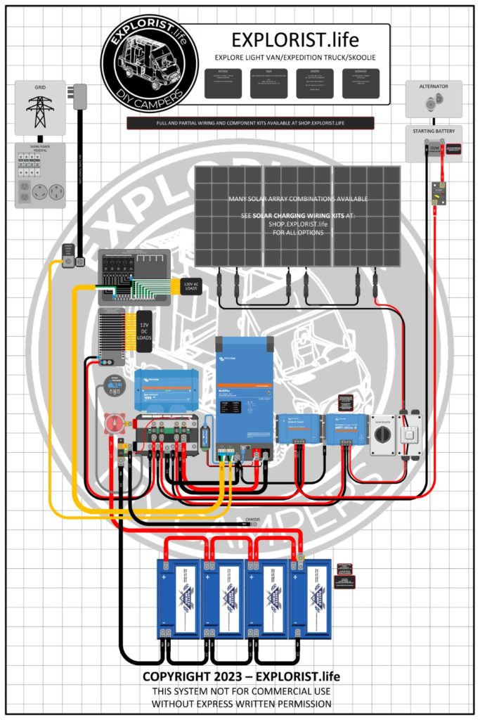
EXPEDITION TRUCK
TRUCK CAMPER
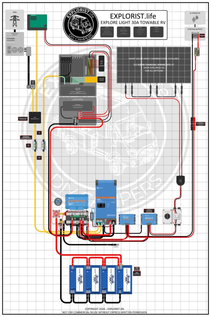
30A TOW-BEHIND RV
30A MOTORHOME

EXPLORE WIRING DIAGRAM
The EXPLORE line of electrical systems is perfect for those wanting a mid-sized electrical system with larger capacities. This line features:
- 12V Victron 3kVA Inverter Charger
- 400Ah Minimum Battery Bank Capacity
The EXPLORE system is available for several different types of platforms including vans, motorhomes, towable RV’s and more. Swipe left/right to see the various options.
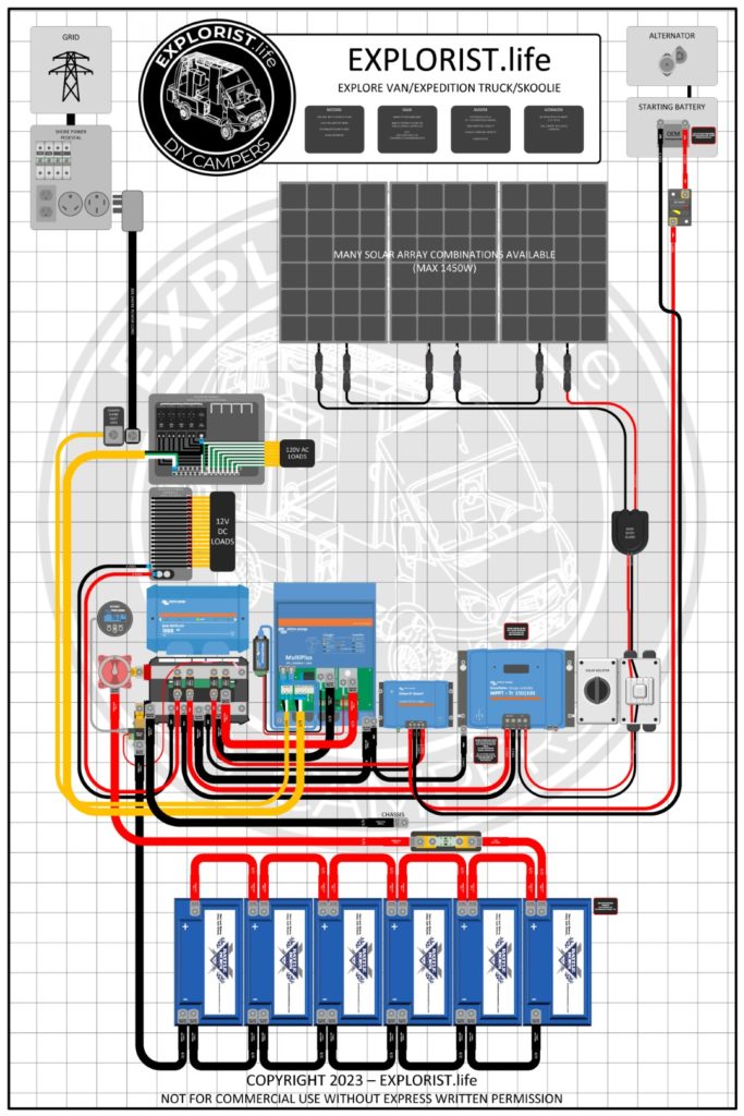
EXPLORE 50A WIRING DIAGRAM
The EXPLORE 50A line of electrical systems is perfect for those wanting a mid-sized electrical system but need 50A service. This line features:
- 12V Victron 3kVA 2×120 Inverter Charger
- 50A/30A/15A Shore Power Charging/Passthrough
The EXPLORE 50A system is available for several different types of platforms including vans, motorhomes, towable RV’s and more. Swipe left/right to see the various options.
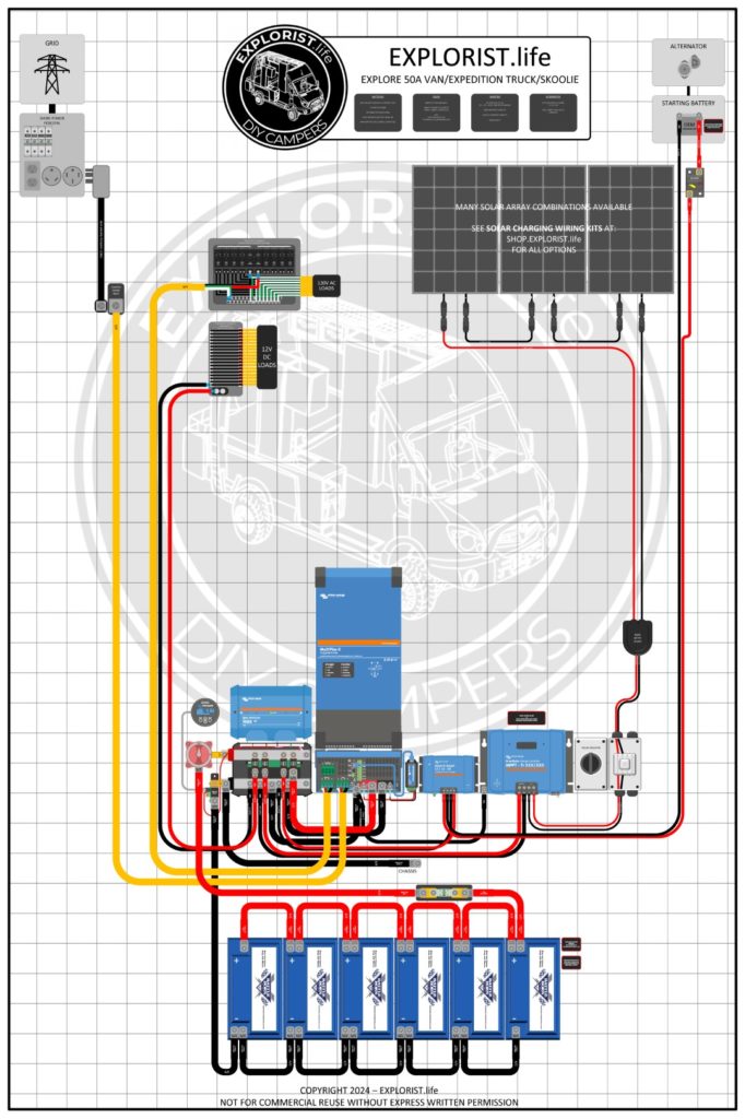
50A TOW-BEHIND RV

50A MOTORHOME

EXPLORE 24V WIRING DIAGRAM
The EXPLORE 24V line of electrical systems is perfect for those looking for a mid-sized electrical system with a very large solar array. This line features:
- 24V Victron 3kVA Inverter Charger
- 200Ah @ 24v = 400Ah @ 12V
The EXPLORE 24V system is available for several different types of platforms including vans, motorhomes, towable RV’s and more. Swipe left/right to see the various options.

EXPLORE MORE WIRING DIAGRAM
The EXPLORE More line of electrical systems is perfect for those who need higher inverting capacities to power large loads. This 24V system features:
- 24V Victron 5kVA Inverter Charger
- 400Ah @ 24V = 800Ah @ 12V
The EXPLORE More system is available for several different types of platforms including vans, motorhomes, towable RV’s and more. Swipe left/right to see the various options.
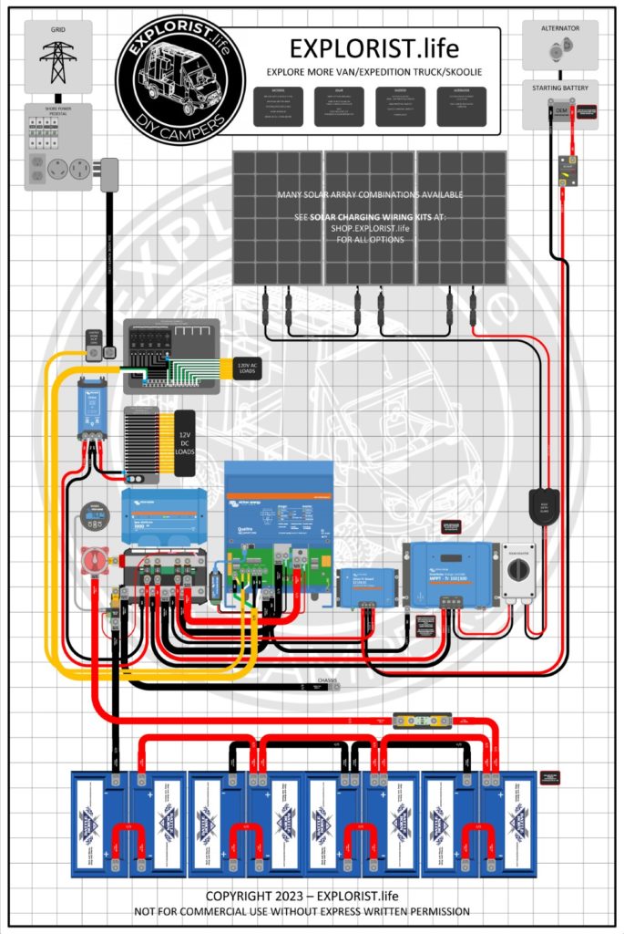
EXPLORE XX WIRING DIAGRAM
The EXPLORE XX line of electrical systems is perfect for those massive projects that need higher inverting capacities, 50A service capabilities, and the ability to power 240v loads while off-grid. This dual inverter 24V system features:
- Dual 24V Victron 3kVA Inverter Chargers
- 50A/30A Shore Power Charging/Passthrough
The EXPLORE XX system is available for several different types of platforms including vans, motorhomes, towable RV’s and more. Swipe left/right to see the various options.
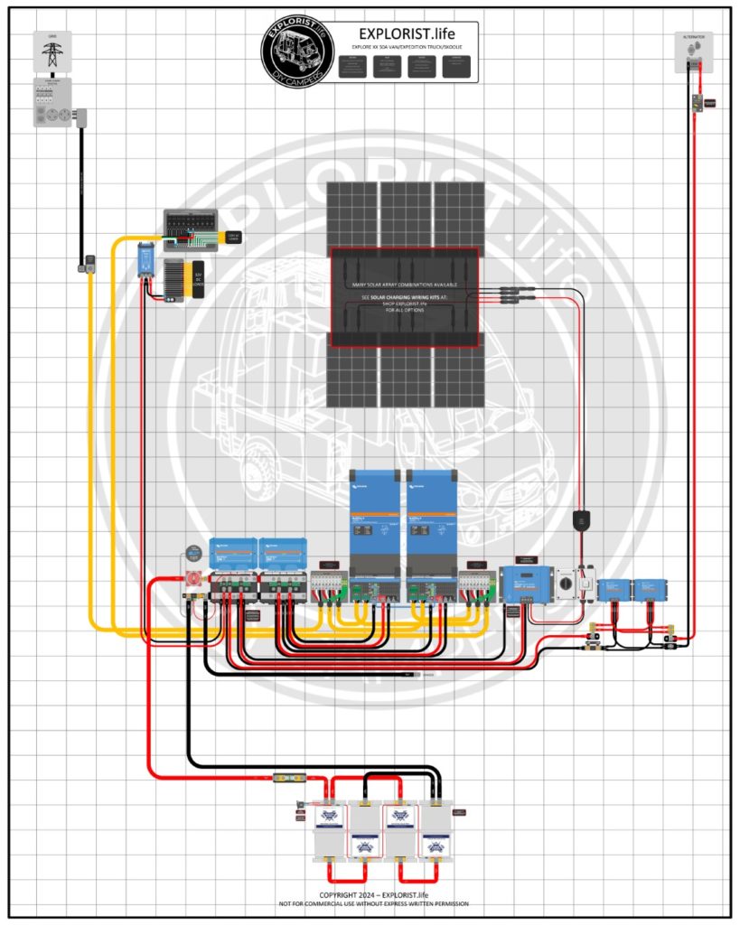
The EXPLORIST.life shop has everything you need for your DIY camper electrical upgrade, retrofit, or complete system.
Subscribe to the EXPLORIST.life weekly newsletter for updates, events, new tutorials & more oppourtunities.

Nate Yarbrough
373 responses.
As 48V components are becoming more readily available, have you explored installations at all and what a 48V system would look like? Victron Multiplus 48V is (soon will be) UL1741 certified. Pros/Cons?
Here are my thoughts on that: https://www.youtube.com/watch?v=sEW-ZaOOlq0
In my 3Kv RV wiring I would like to add second DC2DC charger, do you have a diagram for this?
You can simply copy/paste the entire alternator charging leg of the system over one space on the Lynx Distributor.
Great diagrams and thanks for all you do. I am putting solar in my barn and of course have to go through the permit process. What software did you use for these diagrams? It would be great to submit my permit application with great diagrams such as yours Thanks!
I use microsoft visio for all of my diagrams.
Hey Nate, Amazing site and YouTube channel. I took your advice and purchased from your site all the products except 2 things. My Victron 12v /3000w / 120 inverters. So how do I wire them up together?
Here is a playlist of full installs that will show you how to wire everything according to the diagrams found on the page you left this comment on: https://www.youtube.com/playlist?list=PLmvhcyi4n0TUU8FUc6LE38TBkdSLjdw_5
Hi Nate – I have your 12v wiring diagram- and im having a problem with a simple wiring install; all my 12V overhead lights i want on a dimmer (with on /off) and a simple on / off switch in another location. I followed your diagram- but it is still not working. could this be the type/ model of switch on these LED lights? any help would be great- thanks
This should help: https://youtu.be/WRQuVMFlric
Nate, I’m a subscriber to your channel, thanks for all the work you do. What program do you use to make your diagrams? I’m looking to make one for my system so I can ask/pay for advice on its setup, design, components. I can always hand draw or use an MS Office product but thought there might be something better.
Hey Adam! You should check out the 13:27 timestamp in this video: https://youtu.be/ZHFxLUOG8UE?t=807
Hi Nate! I read that you Highly recommend a dual pole solar cutoff switch , but don’t see any in any of the diagrams? And I wonder if I am to use one, I should install it down stream of the inline solar fuses if I was to add these as well?? Thanks so much for your help.
The dual pole solar disconnect is in literally every diagram just upstream of the charge controller. This is the disconnect I’m recommending now-days: https://shop.explorist.life/shop/all-products/switches-disconnects/solar-isolator-disconnect/
Hello Nate, Thanks for this amazing resource! We are starting from scratch, building out a new “mini” camper van (Mercedes Metris) for weekend/week long trips. We believe we can skip the inverter for now (although we may add it later) but definitely want all the charging options (shore, alternator and solar) and we’d like 2 separate solar inputs (roof-mounted and portable panels from the ground). Can you recommend a diagram that would work for this application? Thanks, Daphne
Sounds cool! I don’t have any diagrams without an inverter.
I have a commercial application in need of a full electrical build. Can I purchase a custom schematic for my needs? As well as a list of all the equipment I’ll need. Most of the diagrams you have are great, but I’m afraid my running needs will be bigger/different. The closest I saw was the 24v 6000w 120/240 diagram. Unsure if a 30a or a 50a build would be better for the 120 AC aspect. I know I don’t want to do a 24v for the DC aspect, I want to stick to 12v. SAMPLE OF MY POWER NEEDS: 2- 15000 BTU A/C units, each needs115v 15a 1725 w 1- electric water heater 120v 16.67a 2000w 1- commercial blower 120v 19a 2280w 1-Shop Vac 120v 9a 1080w Each with its own GFCI outlet and 20a breaker 2- rv 12v fans 1- rv 12v water pump 6- 12v 45” LED Strip high power/lumen output 4 watts/foot .03a/ft Imagine everything running full power for 8-10 hrs daily. Things I think I’ll need, 2- 3000kva power inverter chargers maybe 16-18 lithium ion 100ah batteries, brand to be decided 1 AC distribution panel 1 12v dc fuse panel or a combo of both AC/DC 1 solar charger(definitely will use all day everyday) 1 shore power automatic transfer switch and shore power connections/outlets 1 alternator charger (possibly unable to use this) minimum 4- 100w solar panels, will add as many as I can fit on the roof after install of the fans and A/C. 1 kill switch 1 Bluetooth monitoring unit tons of wires/fuses/terminals/heat shrink and such, and everything else you would recommend (lynx, busbar, shunt, etc.) for such a build. I also have a second build that would need way less, as it will be in addition to a 8k watt Diesel Generator. So that I could probably figure out based on the full electric build. Both builds would be on new Mercedes sprinter vans, high roof, 170 wheelbase, so you have an idea on space available. I can explain to better detail why I need such power if we could talk directly.
I am currently not offering custom wiring diagrams and parts lists, but I already have one publically available that will meet your needs with 2x 3kva Inverter/Chargers -> https://www.explorist.life/24v-6000w-120v-240v-split-phase-camper-solar-wiring-diagram/
Where are all of the older diagrams? The link to those is not working. I’m looking for a simple solar setup without an inverter. Thanks for all of the great videos!
Hey Anthony! I’ve never published a full system diagram without an Inverter.
I did purchase a diagram from you. The Diagram has no accession number that I can see but it is described by you as
https://shop.explorist.life/shop/all-products/solar-wiring-diagrams/200-400ah-battery-bank-up-to-700w-solar-2000w-inverter-dc-dc-charger-wiring-diagram/
The diagram includes a Victron Lynx Distributor 1000
I also ended up with a Lynx smart BMS 500
My Question is … What side of the Distributor does the BMS attach to ( or does it matter ) ?
Thanks, and best Regards Steve Cooke
My diagram does not utilize the Lynx smart BMS. Battle Born Batteries like shown in that diagram are also not compatible with the Lynx Smart BMS; so I would recommend not using it.
Hi Nate, I’m using your diagrams to setup my 5th wheel which came solar prepped with 60V 4Gauge cable battery cable it seems. Any issues pushing 800watts across this? I’m planning for parallel so : 20v 40amp
Or should I replace this now?
Thanks man!
There is no problem pushing 800W of solar panels across 4 AWG wire, but your solar array voltage is too low for an MPPT charge controller to operate optimally. The solar array should be at least 20V higher than your battery bank charging voltage to get the most out of your MPPT charge controller; so consider wiring in series or series-parallel to boost the voltage and lower the array amperage.
Thismlooks fantastic. I am still looking for a van. While I am doing that, I am trying to learn as much as I can so I can hit the ground run in the late winter to spring.
Looking to install 3000 watt inverter,600 watts solar,on a 2021 imagine grand design.I am using Victron system
You’ll be looking for either the 30A or 50A OEM RV Retrofit on this page you just commented on.
Hey Nate, I’m starting from scratch on a new ProMaster build and just about have everything to get started. I’m using a Victron 3000 12v Inverter/Charger, a 150/100 mppt (Overkill), Lynx Power In: fixed to take fuses from your instructional video, BMV-712 smart battery monitor, Victron DC-DC 30 and an Arterra 8930 50 amp combo fuse box.
1). I want to buy one of your wiring diagrams is this the correct one? 3000w INVERTER | 400-600Ah | 400 TO 1200W SOLAR -CAMPER SOLAR KIT.
2). I cannot get the lithium batteries at this time but want to use Six 100Ah Renogy AGM batteries, can I configure these batteries to the 12/3000 Multiplus Inverter Charger?
3). I am also using Six 100 watt Renogy Solar Panels connected in Series Parallel, Do you think this is the best configuration for the MPPT 150/100 charge controller?
I want to use one of your wiring diagrams to make sure I’m using all the wire sizes and fuses. Anything you see that would help me put this together as easy as possible would be greatly appreciated.
Thanks again for you great videos and instruction, you have the best information about this on the internet.
You made that easy on me. 🙂
Hi Nate, I have learned lots from you and am new to this so I am learning every day. I am using BB and all Victron components. I have a question about grounding the case for my Multiplus 3000W and the case of my MPPT 100|30 charge controller.
I notice in your wiring diagrams the negatives from the Multiplus and MPPT go to the Lynx which is connected to the BMV712 shunt which has a chassis ground. Cool.
I also notice that the ground for the Multiplus case also goes to the Lynx, and presumably also gets grounded via the shunt ground to the chassis.
Q1: Is the case ground for the MPPT connected to the case ground of the Multiplus (they are side by side in your diagram – daisychained??) which then gets grounded at the Lynx or does the MPPT case ground have its own chassis ground near the Multiplus? I can’t tell if they are connected.
Q2: I have a non-isolated Orion 12/12 30A charger. It only has one negative as compared to 2 negatives on the isolated version. All of you diagrams have the isolated version. Should the single negative from the non-isolated Orion go to the Lynx (and shunt) as well?
Q3: Kinda related. The support frame for my electrical components / batteries is made of 80/20 aluminum which I also plan to ground. Should I ground the 80/20 on its own chassis ground or should I ground it to the shunt and use its chassis ground?
Thanks and I really appreciate any feedback… Jim
1: MPPT to Multiplus, then Multiplus to Lynx. The 2 lugs on the Multiplus are stacked.
2: Correct.
3: Ground the Lynx Distributor/Shunt to the chassis and then simply attaching the 80/20 to the chassis via bolts/screws is enough of a ground for that as far as I’m concerned.
Friends, I bought the PDF wiring diagram for the system I want to build. That simple diagram, and all the videos that go long with it, really reduces my anxiety about this project. AND the detailed parts list with links to sources is fantastic. With this level of instruction I could do anything – brain surgery, build a space shuttle, anything. Thanks for all of this.
I am wanting to upgrade my 200w Renogy Kit I have had on my Fifth wheel trailer for about 5 years. I am wanting to replace them with 4 200w solar panels, a 60 amp charge controller, and a 3000 watt inverter. I will wire and designate 3 separate plugins in my trailer for 110v from my inverter. I will upgrade the battery bank to 4 12v lithium ion batteries 100ah each. I want to connect my 12v system from my RV that runs the converter to the battery bank. Should that be an issue with anything or should I have any shut off’s anywhere? I know I need fuses between the solar panels and the controller and between the controller and the battery bank. Also I will need a fuse between the battery bank and the inverter. Any diagrams that you could send me would be appreciated. Fuse types and sizes would help if you could send me them also. Thanks. Ray Keen
I’m not sure if you have a camper with 30A or 50A, but there are retrofit diagrams and parts lists for each available on the page you just commented on. Either of those should get you pointed in the right direction: https://www.explorist.life/solarwiringdiagrams/
Like your work,great stuff thanks
I have a travel trailer.40 amp mppt charge controller and 2 100 watt panels that I place out for power. I was also thinking of installing 2 100 watt panels on my trailer roof. If i wire them series parallel will the two panels on roof continue to charge if i have the portable ones put away?
Yep! They sure would!
Nate, do you do custom wiring diagrams? I’d like to have one for my components. If so how much would that cost me?
I am currently not offering custom wiring diagrams, but you can keep an eye on this page for if I open that back up: https://bookme.name/EXPLORISTLIFE/custom-wiring-diagrams Alternatively, my publicly available wiring diagrams at https://www.explorist.life/solarwiringdiagrams meet the needs of 95% of campers.
Hi Nate. We are just starting our research on this project. My question for the 30a OEM RV wiring, we have a generator in our class C, would that be connected in this?
Yep! You would be looking for this one: https://www.explorist.life/30a-camper-inverter-with-solar-and-alternator-charging-wiring-diagram/
I signed up for your newsletter. Thank you!
Which wiring schematic is for your Mother’s Cirrus truck camper please? I have a truck camper as well. Thank you.
Best wiring practices have changed since making the video, but here is the most up to date diagram for a 30A OEM RV Retrofit: https://www.explorist.life/30a-camper-inverter-with-solar-and-alternator-charging-wiring-diagram/
Good day Nate
Firstly, great YouTube vlog! Awesome info!!!
I need a bit of advice with my system if possible.
I ran a PWM controller with a 100w panel on an auxiliary battery that is connected to the starter battery with Cyrix. This only runs a small fridge and worked really well for the past 2 years.
Yet I decided to upgrade the system. 2x100w panels in series with a Victron 100/20 controller. Rest of the system stayed the same. I now get a spiking in the system constantly (unfortunately I can’t attach screenshots). I have checked and double checked for poor connections and errors but all is 100%. Am I missing something?
Many thanks Dewald
If you’re talking about voltage spiking on the solar array side of things, if it works most of the time, it could just be the MPPT sweeping for the most ideal power voltage. If that’s not the case. Triple check all of your connections and then give your charge controller a factory reset and see if a setting was wrong.
hi nate! im having a delima. i assume that your parents camper had something like a converter/charger built-in (june 8 2018 video). i have already bought all my solar equipment for my cargo trailer conversion, and now bought a converter/charger (progressive dynamics 4135) to add to the mix. kinda like the reverse of what people do after buying a camper and then adding solar. i cant find a diagram like this on your website.
i have: renogy 40a mppt controller renogy 2000w inverter renogy 400w solar panels progressive dynamics 4130 converter/charger
i decided to add shore power last minute, for occassional charging and ac/dc use. but cant seem how to figure out how to wire the converter/charger so that i will have 110v recepticals that run off both shore power when plugged in, and solar power when disconnected. id also like to not cycle my lithium batteries once theyre charged, while plugged in. shouldnt i have enough equipment? surely i wont need any more? thank you
The best and easiest way to do that is with an Inverter/Charger (instead of using a converter) like I have on this diagram: https://www.explorist.life/2000w-520w-60a-budget-friendly-camper-wiring-diagram/
I recently purchased two of your wiring diagrams – the 50amp OEM Retrofit and the 24V split phase. I’m working on a 50a 12v split phase setup with two 2000W multi-pluses from Victron.
My question is: on the 24v wiring diagram, you have 6/3 wiring going from the a/c power junction box down to each multi-plus inverter / charger. In looking at the diagram, the L1 wire shows the hot (black), neutral, and ground connected to the a/c busses as I would expect. However, the L2 wire only shows the hot (red) connected. Is this by design or an oversight on the diagram? If it is by design, can I get away with running a single 6/3 wire from the a/c box to the inverters and splicing the neutral and ground to each of the inverters?
Thank you!!
There are only 3 wires going to each multiplus. The one for the L2 Inverter will use 6/3 wire but you should just put a bit of red heat shrink on the ends of the black (hot) wire to denote that it is for L2.
Wonderful information, thank you for all you do. We are designing our system using 640w solar (Renogy 160w panels x4) in series connecting to a 150/45 Victron controller. We have calculated we will use 10AWG wire with 7.92amps running through it (the Imp of a single panel) over about 20ft. We also calculated that would mean we need a 15A fuse on the positive wire before connecting to the solar charger. Is that correct? Your information says to size up (originally calculated 11.88amp fuse) and the 15A is below the maximum fuse size for the wire gauge per the chart provided. Could you verify if this is a correct set up up until the solar charger? Other diagrams we’ve used have a lot larger fuses in similar set ups. Thank you!
If the panels are wired in series, you likely do not need a fuse. More info: https://www.youtube.com/watch?v=s1P31hxlD3I&list=PLmvhcyi4n0TUjVGA_O5aI5SQrS1kKLgEF&index=15
But you will need a solar disconnect: https://www.youtube.com/watch?v=HOXnWXvLXko&list=PLmvhcyi4n0TUjVGA_O5aI5SQrS1kKLgEF&index=15
@Nate Yarbrough, Thank you for your quick reply! You’re completely right, the solar panel has a max series fuse rate of 15A so we do not need a fuse. But we will instead add a solar disconnect per your video.
I’ve looked at most of you video’s and they have been most helpful, Thanks for them. FYI: I got to you because the Victron site mentioned that you are an ambassador for them which for me validates your expertise. I am installing solar on a 25 foot travel trailer whereas you video’s seem to focus on motorized RV’s or build outs of RV’s.
I do have some issues that I cannot find where you might have covered them. One is using you wire size calculator. I know my wire length is going to 12.5 from panels to inverter for a total of 25 feet. I have to assume that I need the data for my panels to determine the other information, volts/amps. As an example my system consists of three panels; I am using the REC 330 watt panels whose specs are: Vmpp=34.6, Impp=9.55, Voc=41.0 and Isc=10.33. How does one use that information to fill in the the fields in the calculator for amps and volts? An explanation in the calculator would help.
I would also like a one time consult via your private group, can I join for a month to have a review of my system and get suggestions for improvement without having to have continuing membership?
Here is a tutorial that will teach you how series vs parallel vs series-parallel wiring of solar panels affects the array voltage and amperage: https://www.youtube.com/watch?v=KJ5zCY5EBeQ
My private group is a month-to-month kind of thing. It auto-renews monthly, but you can cancel any time and not be charged for the next/subsequent months.
Hey Nate, Your an invaluable resource man! Ive watched most of your videos, the content is fantastic and easy to follow.
Have you ever used the Growatt 24v 3000w style all in one systems? they seem to be a great budget solution for travel trailer use . As much as I would like to do separate Victron.. it would be over 3x the cost. would you ever consider doing wiring diagram and a video doing a build with one of these units?
Glad it helps! There is a good chance I won’t do a system like that. Not anytime in the foreseeable future though. Hopefully, the skills and concepts I teach coupled with the diagrams I have already published will help you put together whatever kind of system you are after. If pinching pennies is the goal, here is the least expensive system I can recommend at this time: https://www.explorist.life/2000w-520w-60a-budget-friendly-camper-wiring-diagram/
If I start introducing too many different manufacturers, people start getting analysis paralysis and it makes teaching this stuff exponentially harder. Victron provides me with TONS of training and access to their engineers and R&D team to help me learn as much as I can not only about their products, but about system design in general, and that in-turn, makes it so I can more effectively teach this stuff to everybody.
Hi Nate – We recently purchased a new Jayco Eagle TT and I contact BB to put a system together for us. Our TT has 50a service. So they recommended we buy two (2) two-thousand watt investors instead of one 3000 watt so that all the ac plugs work in the rig. Do you or would you be willing to post a wiring diagram showing 4 100ah batteries and two 2000W Inverters connected together for a rig with 50amp service? Thank you!!!
Here is a diagram for a 50A OEM RV Retrofit: https://www.explorist.life/50a-camper-inverter-with-solar-alternator-charging-wiring-diagram/
And here is a diagram for a dual multiplus setup: https://www.explorist.life/24v-6000w-120v-240v-split-phase-camper-solar-wiring-diagram/
Hi Nate, the second diagram for a dual Multiplus setup is for a 24V right ? would it be possible to still run 4/0 wires in a 12V setup using two of the 12V 3000W Multi ? thanks
I do not recommend a 12V battery bank for 6000W of inverting power.
I have a couple questions regarding the breaker I should use between the panels and the charge controller. I eventually plan on having 1000w of solar on the roof and using your MPPT calculator in addition to Victron’s I have purchased the 150/70 MPPT. Now, also according to your calculator it says that I can expect to see 58.8 amps going into the charge controller (using specs from the panels im looking to get).
SO, with the potential of 58.8 amps running through the cable from the roof to the controller and using your fuse calculator, I believe I’ll need to step up the cable (probably going to run 2awg) and also expect to use a 80a breaker. Does this seem correct? Thanks for your help.
– Nick
Basically, with an array amperage that high, you will need to use something like this: https://amzn.to/3bfy0D6 I do think something has gone wrong in your solar array planning, though… That array amperage is REALLY high. I always shoot to have array amperages under 30A so I can simply use MC4 connectors, fuses, and a single breaker. I would HIGHLY recommend re-working your solar array plan so that the array is under 30A. This will likely mean wiring in series or series-parallel depending on the specific panels and number of panels you are trying to use.
@Nate Yarbrough, Interesting. Its five 200W panels in parallel. Newpowa model on amazon. Perhaps I listed something wrong using your handy calculator?
I would very much recommend re-plugging those numbers back in as wired in series. You will get MUCH better performance with those panels wired in series (and can use 10AWG for all of the wires if you go that route). See the 5x200W solar panel wiring diagram example in the ‘Solar Parts List’ section of this page: https://www.explorist.life/3000w-inverter-400-600ah-400-to-1200w-solar-camper-solar-kit/#solar-parts-list
Nate: I called BB batteries and ordered my system using your 30 amp solar/alternator schematic. Since I dont plan on using more than 400 watts of solar, BB recommended that I buy the lesser 100/30 charge controller, rather than the 150/100 as spec’d on your diagram. Will this be a mistake or problem down the road? I plan on subscribing to your monthly consulting service once the eqpt arrives and weather clears so that I can start building. Thank you! ~Dave Blood, Camino, CA
I have the 100|30 recommended in the “400 Watts – 4x100W Solar Panels – 12V Battery Bank” solar parts list at the bottom of this blog post: https://www.explorist.life/30a-camper-inverter-with-solar-and-alternator-charging-wiring-diagram/#solar-parts-list Under the “Solar Charging Parts List & Wiring Diagrams” header.
Hi, I would like to join your private group but the link does not work. Also, I am interested in the budget friendly guide with the renogy 2000w inverter but, I will be using a 3000w inverter. Will that change anything else other than the cables from 2/0 to 4/0? Thanks!
Private group link: https://community.explorist.life
The wires, lugs, fuses, and busbars would all need to be different (bigger) similar to this 3000w system: https://www.explorist.life/3000w-inverter-400-600ah-400-to-1200w-solar-camper-solar-kit
@Nate Yarbrough, oh okay, I will review the one you sent instead. thank you! Do you review wiring diagrams in the private group?
I do indeed review diagrams, but… The need to be based off of the same designs and principles as shown as the diagrams found on this page AND you must have specific questions about your diagram that I can answer. The more specific questions you have for me, the better I can help.
@Nate Yarbrough, makes sense. I just plan on combining the budget friendly wiring diagram and the one you provided since I am using renogy products. Thanks for the help!
Hi Nate, This might be a simple answer but would rather be safe then sorry.
I currently run a 20A renogy dcdc charger to charge my 100Ahr lithium battery, which runs my 40lt fridge which is 55w@12v.
The problem I have is I don’t do big drives so my dcdc charger doesn’t get times to charge up battery, I also have a 300w solar blanket but don’t want to pull it out every day to top up battery.
So I have been thinking why not pick up a cheap 48v house solar say 250-300w and run that on roof of vehicle through a MTTP 40w charger.
I’m pretty sure this will work? but I wanted to know if parked up could I put both solar to battery to charge at same time or couldn’t this be done as they are different volts?
You can have both solar and DC-DC charging connected to your system at the same time, but they won’t ‘combine’ charging. Victron components will be able to ‘combine’ solar and DC DC charging in the near future, but to my knowledge, that’s not something Renogy is working on.
I wish to build out a 7×16′ cargo trailer with both 12v@120v power. I don’t know what size solar panel/s I need, hoping for a suggestion. I’m retired, and would like to travel this coming spring thur late fall 2021. Thank you in advance, any help would be great. Skip Brooks
Battery Bank Amp Hours (at 12V) x 2 = Recommended watts of solar. However you get to that number, doesn’t REALLY matter (try to avoid mix and match solar panels). Here is a list of solar panels in various sizes I like: https://www.explorist.life/best-solar-panels-for-a-diy-camper-van/
First off let me say you are freaking awesome sir. I’m subscribed to your YouTube. I’m a builder with very little electrical knowledge and even less solar ( all of which I have learned from you). I am building a very simple setup in a 1989 ford e150 for myself and my awesome border collie Harley Quinn ( no my son named her lol ). I will have a charging station for my phone laptop and go pro, a vent/fan in the roof, and a small refrigerator (dorm room sized)(may or may not depends on worth versus cost. I’m just fine with MRE life lol.. I will be using propane for heat and cooking and have no plan for air-conditioning (If ya have an idea I’d love to know your opinion).
My two options I’m thinking of for power:
Two 325w panels (mounted on the roof)(seems like to much but??), breaker box, controller (guy suggested 40 amp?), battery(guy suggested 2x100amp/h lithium batteries or he was going to combine two to make one?), inverter(he suggested 1000w Epever), and all the wiring of course…… total cost around $1500.00.
my second choice would be a portable system, like a ……. Bluetti – 2400Wh/1000W Power Station: Super Long Lasting 2400Wh Power Station with High Load Continuous 1000W Inverter (1000W≤load<1200W@120S; 1200W≤load@1s) This Power Generator Can be Recharged from the Sun with Solar Panel , Input Voltage must be 16V~68V) or by wall plug. this set up is $1700.00 without panels
Jackery Explorer 1000 Portable Power Station …. 1002Wh(46.4Ah) lithium battery capacity, 1000W Rated Power and 2000W Surge Power. Multiple output ports: Two USB-C, two USB, one DC carport & three AC outlets (with the pure-sine wave) Efficient solar charging with MPPT built-in. this set up is $1000.00 without panels. also they make a all the way down to 160w ones.
I'm not sure how much panel juice I need for either of those my assumption is around 200w total for the smaller one and and 500w total for the bigger one. info on me… I'm a minimalist and my comfort needs are low. so I guess my question is based on my needs would all three work?? what would you suggest?? and if I get the portable ones could you suggest a panel w/specs watts/amps/volts?? and if you suggest going ahead and installing a fixed setup I would love your opinion on the power diagram
I would probably recommend either the Bluetti or the Jackery (You’ll have to decide if you need more vs less power by performing a power audit: https://www.youtube.com/watch?v=a406IxiU-Xg Just focus on the Amp Hours Used Per Day output when you get to the bottom. )
I would be wary of somebody saying they could install 200Ah lithium batteries, a 40A charge controller, 1000w Inverter, Breaker Box, and all of the wires for $1500, so I would not recommend that route. Lithium Batteries by themselves cost that much or more depending on the brand he’s using.
For panels… here are the panels I recommend, in general, but you’ll have to see what the max voltage input for the two units are and design the array to stay below that threshold: https://www.explorist.life/best-solar-panels-for-a-diy-camper-van/
Looking into adding solor system on a 95 lance 11.3 trk camper and being able to run a CPAP machine all night
Sounds like a great project. Hopefully you’re finding what you’re needing here. 🙂
Hey, I purchased the Aims 4000 watt split phase 240/120 inverter charger. I’m going to implement this in lieu of the Magnum you show on your 50 amp OEM RV retrofit diagram. It comes with a built-in transfer switch and battery monitor that is Bluetooth capable. I’m also going to omit the alternator charger portion for now. Can I still safely use your diagram with this equipment while omitting the battery monitor and leaving room for the alternator charger on the lynx distributor if I so desire to add it in later? Thanks for your help, I always learn a lot from you and really appreciate you putting out all this great info.
If you want to stray away from the parts list and components on the diagram, you’ll have to do your own due dilligence on the part you want to swap out. For example… the Aims only has a 40A transfer switch and the AC input and output terminals are only rated for up to 8 AWG. So, if you are planning on installing this in your camper with 50A shore power… the 6 AWG wire from your shore power connection will not fit. This is the biggest reason I did not use that unit in that diagram.
You should not omit the battery monitor. That would be like driving a car with no fuel gauge. I consider the battery monitor a piece of essential equipment.
Alternator charging can indeed be left off until it’s desired.
@Nate Yarbrough, Thanks Nate, After further investigation I must agree with you on the battery monitor and will be adding those components. So, will I not be able to pass through 50a shore power with this inverter? Will I have to change my input shore power to 30 amp? This would be a discouraging discovery. Thanks for taking the time to help me.
Ultimately there would be quite a bit that would need to change. It would have to be 30A Shore power, but 120V/240V 30A shore power, which really doesn’t exist. Ultimately, for that reason, I cannot recommend that inverter for a 50A OEM RV replacement and is the biggest reason I did not include it in that diagram. My recommendation is to unfortunately send that inverter back and go with the components I have spec’d in the diagram.
Hi Nate, thanks for sharing your knowledge. Can you clarify the installation of the Victron Orion? It is listed here as connecting alternator to house battery. I have read from others that it should be connected battery to battery. What is the best way to do this? Thanks
It is to be connected to the battery. You’ll notice that in my illustrations, it is connected to the battery as it also is in the Victron supplied instruction manual.
Will the 3000w inverter paired with only 300ah of Li battery cause problems? I’m trying to avoid the cost and excess weight of an additional battery if possible.
Thanks for all of your info.
The 3000W inverter is indeed only compatible with 4+ batteries.
Is a lynx distributor necessary or can you also connect your 12v cabels at the same plus and minus pole of your battery where you connect the thicker cabels coming down from the mppt charge controller? I only have one huge 300Ah battery.
It’s best to use some kind of busbar to make all of those connections so there aren’t multiple connections at the battery. The Lynx is the best option for this.
are these diagrams for 24v ?
All of the ones with smaller than 3000w Inverters have 12V battery banks. This is the only diagram I have that needs a 24v battery bank: https://www.explorist.life/24v-6000w-120v-240v-split-phase-camper-solar-wiring-diagram/
Would like to learn more two wire my RV with solar
Great! You’re in the right place. 🙂
Hi Nate Regarding the drawings I did not receive it can you send it to me And can we communicate throw what’s up if your mail not working Thanks
Please try my email again. [email protected] I get emails every day, so I do not think my email address is non-functional. I do not have whatsapp.
Do you have any diagrams for smaller set-ups? I’m bringing my Delica back to the states with me in March and getting a small solar set-up is high on the list of what I am looking to do when I get back.
These diagrams seem very useful, but a bit overkill for what we will be trying to do!
The smallest diagram I have is this one: https://www.explorist.life/2000w-inverter-200-400ah-lithium-200-to-700w-solar-camper-wiring-diagram/
Any smaller than that and I usually recommend getting some kind of Goal Zero all-in-one unit.
Hi I order a diagram and pay 10 $ but I can’t download it because there is problem in your site Thanks
Send me an email at [email protected] and I’ll re-send it.
can you explain why on your 30 amp electrical diagram (I just purchased) on the 120v shore inlet of side the inverter you have a 10-3 and the outlet is a 6-3 what is the reasoning for the upsize in wire? Thanks in advance. The line diagram is very nice easy to read and understand. thanks
Sure! I explained it in pretty good detail in this video at the 35:17 mark: https://youtu.be/JMqtVBN26NQ?t=2119
That upgrade only needs to be made if your breaker box is capable of handling more than 30A; so please verify that before making the change.
I redid the math and the calculator and I found the last few missing numbers. I also changed the wiring of the panels. So that question got answered 🙂
My second question stays the same – with a little bit of a different look to it:
The numbers I got out this time where these: Max V/ Panel = 48.68375 Volts per Panel Max V = 146.05125 Total Volts in Array Max A going into the MPPT = 10.14 Amps Max A coming out of the MPPT = 68.75 Amps The recommendation is the Victron SmartSolar MPPT 150|70. I wonder why that is so? Why not the 150/35 or the 150/45? Or anything with a lower second number? Because I thought that for the selection of the MPPT the incoing Amps, so those coming from the panels, where the ones that mattered?
Yours sincerely, J
PS: You can ignore my previous comment (:
The 2nd number in the SmartSolar MPPT xxx|xx is for output amps. Not input amps. More info: https://www.youtube.com/watch?v=MxziHKvTRh8
I’m about to buy a 30′ campers and make myself the most autonomous. I looked at mobile-solarpower.com and I stopped on the RV/Cabin 24v system which includes the Mpp Solar 24v, 2.4kw. I will add 1200w of solar panels and 2 Lithium batteries 12v, 100ah. This was my initial plan until I saw the LEOCH. I like the idea of having a portable system with the same battery power. Now as I’m new to solar system 😉 I have 4 different options and I can see a little bit the differences but maybe I don’t see everything and I would like to have your opinion.
So the 1st option : is the original system mentioned above, 3 solar panels of 400w connected to the 24v Mpp Solar connected to the batteries (2) and to the campers (i.e. no portable system).
The 2nd: is 3 solar panels of 400w that goes to 24v Mpp Solar, which is connected to Leoch (which replaces the batteries) and campers.
The 3rd : Only having 2 panels of 300w (600w max allowed by the Leoch) directly connected to the Leoch that goes to the campers but I lose half of watts (which I don’t like very much).
The 4th : is to have 2 separate systems: 2 panels of 250w connect to the Mpp Solar 12v, 1kw ( instead of the 24v) connect directly to the campers, 2 other panels of 250w connect directly to the Leoch which connects to the campers. (I put 250w because the mpp solar 12v doesn’t take more than 500w and I wanted my panels to be all of the same capacity).
Knowing that : my main goal is to settle down in my camper and having more power in case of future projects. My current usage right now is 600w. Where I am moving there will be 11h of sun everyday (no winter). So I think I don’t need a big battery bank.
Which of the 4 options are more suitable for my situation? Thanks
I don’t know much about the systems you are talking about, so I would recommend option #5, which are the systems I have designed for that purpose.
1: If your camper has 30A shore power: https://www.explorist.life/30a-camper-inverter-with-solar-and-alternator-charging-wiring-diagram/
2: If your camper has 50A shore power: https://www.explorist.life/50a-camper-inverter-with-solar-alternator-charging-wiring-diagram/
I just used your Calculator for the MPPT Charge Controler and I’m a bit confused about the result: The numbers I got out were these: Max V/ Panel = 48.3875 Volts per Panel Max V = 96.775 Total Volts in Array Max A going into the MPPT = 16.9 Amps Max A coming out of the MPPT = 76.39 Amps -> The recommendation then was the Victron SmartSolar MPPT 150|85 -> following the Amazon-Link I found the “victron smartsolar 75|15” While being confused about these two different results I wondered how the recommendation ended up to be the 150|85. Why not the 100|20?
To be honest I also had a problem filling in all the data needed – because I couldn’t find quite a few of these points in the solar panel spec. I will just add all the Information I could find – and hope that maybe you know what I’m doing wrong 🙂 So here comes a list (the info is German, so I tried my best to translate it): Pmax – Max. Leistung[Power/Output?] = 110 W Voc – Voltage open circuit = 39,5 V Lsc – Kurzschlußstrom[Short-circuit-current] = 3,46 A Vmp – Max. Systemspannung[Voltage] = 33,50 V Imp – Max. Strom[Current?] = 3,28 A Ptol – Leistungstoleranz[Demand/Output allowance?] = +/-5% Solarzellen[the cells] = ActiveWire Flex Solarzellen (> 20% Effizienz) Ausgangssorte[… type?] = +/- Kabel (1,5 M)
I would love to here from you because I really need to find the right answer(s) and you have given great ones already! I I truly don’t know any platform about electricity that is that easy to understand than yours! Keep up the great work! 😀
The 2nd number of ‘SmartSolar MPPT xx|xxx” is the amps coming OUT of the charge controller; that is why the 100|20 would not work seeing as you have nearly 80A output from the charge controller.
Hi Nate, I see on your wiring for the 30 amp OEM RV solar retrofit. There appears to be no battery disconnect switch. Also can you explain why the chassis ground goes from the MPPT to the Multiplus instead of just going to the chassis ground. I’m new to all of this and learning much each day. You have by far the best wiring diagrams I’ve seen.
I simply forgot to add the switch. Oops! I’ll revise this after Christmas. You can see where the switch would go in this diagram: https://www.explorist.life/3000w-inverter-400-600ah-400-to-1200w-solar-camper-solar-kit
The equipment ground just needs a solid path bath to the battery bank. If the chassis is used, it makes the path less direct, that is why I run it how I have.
HEY NATE! looking to build a 600ah system – your diagram is excellent but wondering about the actual panels – the top of our 170 sprinter only has enough room for 3 large panels – but all the ones I have found in the 350-400w range have high voltages (such as the maxion 3 – I am finding this to be true for most higher watt panels). Using your calculator – wiring all 3 in series – I come up with about 252 max voltage and 93 amps our of the controller. This seems to be a little too high for the 250/100 Victron controller – any suggestions – different panels or controller?
Wiring the panels in parallel to lower the voltage to a more appropriate level would be the best option for that setup.
I’m using lithium batteries. Is a temperature probe needed when using the Victron 712 monitor or should I get it without the probe?
Either way. If the batteries are inside of the heated/air conditioned space; it’s less important to have the temp probe. If the batteries are outside of the heated/air conditioned space, it’s more important.
I’m about to start my install, 840w (4 panels) with 400ah BB batteries, waiting on delivery. I’ve been binge watching your videos, great resource, thank you for sharing your wisdom with solar.
Nice! Glad it has helped. 🙂
Are the diagrams for the camper vans 12v and 24v friendly in terms of wire gauge??
As of writing this reply, all diagrams on this page are for 12v battery banks.
Hi Nate, Do you have 48 v dc wiring system using the Quattro 48/3000/35 ? Please share if you have one. Thanks!!!
At this time, I do not have a diagram for those specs. Sorry about that!
Hi Nate, I’m looking at the Victron MPPT 150/35 you recommend on Amazon for $295. I’m seeing a Renogy MPPT 40a with bluetooth module for $140. Is the Victron worth the extra money in your opinion? If so, why?
The Victron SmartSolar MPPTs have better reporting of data than the Renogy charge controllers, in my opinion. If you are trying to save a few bucks and need less than 30A to handle your solar array, maybe look into the Victron SmartSolar MPPT 100|30. That’s more comparable in specs to the renogy you’re looking at with a lower price than the 150/35: https://amzn.to/2MiAdF9
Hi, I thinking about building a light weight foldable, portable system with 10 x 160 watt flexible solar panels tied together, 2 series x 5 parallel. But use far less battery then what you show in the above examples for the following reason. When the cells are operating in the day is when I will need the most power (i.e. appliances, computer, power tools etc.) I was thinking of 2x100AH battle LI batteries for a total 200AH. If I average 1000 watts of the solar throughout the day, I should have 600 watts left to charge the batteries. Then use the batteries at night. Basically, sufficient solar wattage for both day electrical use and charging batteries from previous night use. Is there a reason why your above examples have very little solar wattage (it looks just barely sufficient to only charge the batteries)?
I recommend sizing the battery bank to match daily energy consumption needs and then sizing the solar array to refill the battery bank within 6 hours (1 day).
I’m in the beginning stages of planning and building an off-grid teardrop trailer. Wanting to keep it simple, but realizing a power system with enough juice to power a 12v fridge freezer, a few LEDs, and a water pump is necessary. This has been the best explanation I’ve found thus far. One question: how would chassis ground work if the trailer is completely aluminum?
Chassis ground will be the same on aluminum framed campers. Just chassis ground to a substantial chunk of metal connected to the rest of the body/frame of the camper.
I am using a YueQing pure sine wave inverter 3000w there is no AC in port for the shore power to go in i think. How do in hook the inverter power up to the main breaker of my 5th wheel where the shore power is going?
If there is no AC In, it is just an inverter and not an Inverter/Charger like what’s on my diagrams. It can be done, but you’ll have to refer to the user manual and understand how it plays into the system because I do not have any diagrams that are Inverter only. Here is the closest thing I’ve got to retrofitting a Inverter Charger into an OEM RV: https://www.explorist.life/30a-camper-inverter-with-solar-and-alternator-charging-wiring-diagram/
Can I just hook up the inverter to the same breaker as the shore power is and add a 30a breaker on the wire coming from the inverter so when the shore power is operating i can turn off the breaker to the inverter?
Nate, What is your take with 2 Sunpower 435 watt solar panels with 2 105A 12 volt Lithium Phosphate batteries. Max Voltage is 73 volts and 5.95 amps. I would also like to be able to charge by AC. Any recommendations.
Of course! My recommendation is to follow the diagram that is most appropriate to your setup found here on this page. 🙂
Hello, Nate excellent videos and DIY info, the best I’ve seen out there. I watched the video “How to Wire Solar Panels in Series Parallel” @ time 3:12 you show that you can’t have a parallel connection with different number of solar panels. Im assuming that you cant do this because the voltages are different? What Im trying to do is have 2 panels (12) fixed to the roof(series) and have one mobile one on the ground so I can move it around. Im also assuming if I get a single 24v mobile panel I could wire the system in parallel??
Hey Todd! I just released a blog post talking about that concern specifically. Here is a link to that: https://www.explorist.life/using-mismatched-solar-panel-sizes/
Hi.. I’m just digging into your site and have lots to learn but If I want to do a 200/400 system and either a 2k or 3k inverter would your wiring kit still work for that or is it only going to work for the loads you outlined?
If you check the description on the product page, it tells you what types of components the kit is set up for. If you want to stray from those components, you will need to do your own due diligence to determine if the kit will be compatible or not.
What’s your take on 4 x 100W solar panels vs 2 x 200W solar panels? Other than price, V, and space I see no major difference when matched up with a 100V/50A charge controller
Either way. It doesn’t really matter.
Morning Nate- I’ve been looking through your wiring diagrams for a non solar 200-300 AH lithium battery bank system (with alternator and shore-power charging). Is there an easy/appropriate way to “trim” the solar from one of your existing diagrams and parts lists to arrive at a final product?
For the diagram, yes! Just ignore everything from the positive and negative busbar to the charge controllers.
For the parts list, not really, you’ll have to go through and count how much of what will need to be removed from the parts list.
I have a question about your parts list. My set up is: solar-600w, 4-100ah battle born batteries, 3000w inverter. Using air fryer at times Stove top 2burner, fridge/freezer lights, plug in for laptop other Devices.
I feel like we will need a few items not on your solar camper parts list, for example a bus bar? If so what brand do you recommend?
Sure! So, You’d be looking at this diagram: https://www.explorist.life/3000w-inverter-400-600ah-400-to-1200w-solar-camper-solar-kit/
The Victron Lynx Distributor in the parts list is the furthest left blue box on the diagram and actually IS the positive and negative busbar. There is a positive and negative busbar with 4 fuse holders contained in that nice pretty blue box.
Hi, Nate et al! Question about PV panel sizes… We are planning our solar/battery set up, and it’s similar to the 200Ah-525W diagram that is on your site. Can we use two 380W 72-cell panels instead of three 175s? Trina has a 380W panel with 12v DC charging compatibility, but will the 150/60A charge controller cause a problem or result in power loss?
We are winter/ski people so more production is OK, and hoping to add another 200Ah battery down the line. Is this a good choice?
You can, indeed, use 2x380w panels. You would just need to size your charge controller appropriately for the array specs. Tutorial – How to size a charge controller: https://www.youtube.com/watch?v=MxziHKvTRh8
I will be doing a DIY soon and while your wiring diagrams are a gold mine I don’t think I’ll be starting off with Lithium due to cost how can i apply your diagrams using AGM battery bank? Do you have diagrams from your AGM system? I am looking to have around 800-1000 watts
All of my diagrams will work with AGM batteries as well as Lithium. 🙂
Hi– I’ve read through a bunch on your website–super helpful; thank you! I’ve got a question that I didn’t see answered.
Can I add “shore power” to my vehicle so I can run the vehicle A/C off the campground pedestal? I keep finding info on charing batteries, etc. but I’m looking to do something more basic. At least I think it is. 🙂
If it is your engine run air conditioner, shore power would not help because the compressor on your vehicle engine is run off of the crank spinning which requires the engine to be running.
Hi ? I’ve been following you on YouTube and your site. I’m wanting to purchase a wiring diagram but unsure which one would be suitable for the products have.can you guide me please? I’m located in Australia so unsure if that makes any difference. But I have The victron Quattro 48v 5000 Victron Orion tr 712 Battery monitor Victron mppt 100/50 8x 350w 12v panels This is for a 40ft bus ? Which is a 24v system Our bus is set up with 12v And 240v (wiring up still) I am hoping for 4x lifepo4 100ah batteries (but unsure if this will work) or if I need to look at other battery in 48v options. Is there a wiring diagram that would suit our application? Any help appreciated ? Jacqui
Hey Jacqui! That’s going to be a great setup. 🙂 Unfortunately, I don’t have any wiring diagrams available here on EXPLORIST.life for a setup like that. For diagrams, the best I can offer is my custom wiring diagram service and you can find out more information about that on this page: https://www.explorist.life/consulting .
Hi, On one of your wiring diagrams it shows three 300W 24VDC solar panels powering a 12VDC system. Please explain?
All of our diagrams feature MPPT charge controllers which regulate a high voltage from the solar panel array down to a usable voltage from the charge controller. For example: the Victron SmartSolar MPPT 150|100 can take up to 150 volts from a solar panel array and regulate it down to the 13-14v it takes to charge a 12v battery bank. More info about how a charge controller handles this: https://www.youtube.com/watch?v=MxziHKvTRh8
Trying to fit the maxium solar on my van (the vent breaks the space up). Question: Is it not advised to use different size panels?? Also, is it best to stay with the same brand? Do not see this addressed anywhere on your site. Thanks
You CAN use different size panels, but all like-sized panels need to be connected to their own charge controller. So, for this reason, it’s best to match solar panels.
Hi Nate, I have 4x100W Solar panels and 300Ah of LifePO4 Batteries. One major change for my system is that I have a 3000W inverter (due to a lot of Watts coming from an electric water heater). So with a 3000W Inverter (9000W @1s, 4500W@3s, 3600W@10s) do I size the fuse for the continuous 3000W (3000W/12V=250A) or for maybe 3s Surge 4500W/12V=375 rounded to 400A. I dont see the continuous Amp draw of the water heater plus other draw that may be running at the same time (120V mini fridge, Small 300W blender, etc) exceeding 3000W. A lot of generic sizing online suggest 400A Fuse with 4/0 wire for a 3000W inverter. At 3000W 250A fuse and 2/0 wire could work but at 4500W a 400A fuse with 3/0 (385A max is cutting it close to 375A) and max surge is 9000/12=750A which max’s out ANL Fuses and exceeds 4/0 wire max amps. So do you size your fuses and wire for the rated output of the inverter or for the surge and Do you ever size fuses and/or wire off of max possible surge. Best regards, (Apologize for rambling) Jay
I think this may help: https://www.explorist.life/3000w-inverter-400-600ah-400-to-1200w-solar-camper-solar-kit/
Hi Nate, how are you? jus a quick question, we are using your spreed sheet for the power audit, but we are in Australia, so our appliances are 220, how do we do? any way to change it ? thanks!!
Nothing will need to change as far as the power audit goes. Any place it says 120v, just substitute it with 240v. The math stays the same.
Nate, Do you ever recommend 3000W Victron Multiplus inverter chargers? If using it, would you not need a dongle?
I do recommend 3000w Multiplus units. I just released a diagram featuring them: https://www.explorist.life/3000w-inverter-400-600ah-400-to-1200w-solar-camper-solar-kit/
You’d still need a dongle for bluetooth connectivity.
I join the chorus of thanks from those above for your excellent diagrams and your willingness to answer questions.
One thing I am wrestling with is the need to run individual negative wire runs back to the DC distribution centre. The negative bus of the distribution box is connected to the main negative busbar and then to chassis ground. I have about 10 dc circuits going from the driver side where my electrical closet is to the passenger side where the kitchen is. I was thinking of consolidating all my negative runs to a passenger side negative busbar terminated to a passenger side chassis ground.
I may be very naive, but I am not seeing a downside to this – less total wiring and number of connections. I am not sure if the ground conductor composed of the chassis sheet metal would introduce appreciable resistance vs a properly sized copper wire back to the distribution centre bus.
Many thanks!
You could definitely do that. That’s more of a personal preference on which way you want to do it. No real right or wrong answer to that one.
I understand that the 12vdc system grounds to the chassis. Does the 120vac system ground to chassis or is the ground run separately without ground to chassis?
Nope. The grounding on the 120vac side of things is done inside of the inverter.
Late Spring 2020 is when I will have our new Transit AWD van. For our power needs I’m looking at GZ Yeti 1400/3000 unit to power the van. I’ve seen a few videos that show the basics how to Integrate the GZ using a 12v fuse block, setting an outside shore power connection and connecting the car power using their Charging Link. How do I contact you when I’m ready for a custom wire diagram and a consult?
Nice! You’ll be able to get ahold of me here: https://www.explorist.life/consulting
Hi Nate! I’ve seen you recommend a 175w Newpowa solar panels. They have a dimensional drawing that says those are over 58″ long. Without a roof rack, the OEM sprinter rails can really only accommodate ~51″
I tried the Richsolar 190w panels that are ~58 3/4″ wide and even fabricated custom mounting brackets. I hated the look of them hanging over ~2+” on either side and the sides flare about above the roof rails toward the front, so the bracket ends up resting on the painted van (rather than the rail) which is no good.
I guess most people mount them on crossbars that are mounted to the rails? That raises them up quite a bit and probably causes a fair amount of drag which decreases gas milage.
Oh, after writing that I realized if I bolt the two Richsolar 190w panels together and turn them sideways then the width of the double panel is about 53.6″ which fits perfectly on the OEM rails.
We have the 175w Newpowa solar panels on our van and are fine with the overhang. I recommend that everybody take measurements of the solar panels and verify they will work for your own needs.
Hey Nate, thank you so much for the detailed information, your blog is incredible!
I am trying to use your link “CLICK HERE TO ADD ALL AMAZON PRODUCTS TO AMAZON CART” for the LI-BIM and all of the additional parts needed and the link is broken, only adding the Momentary switch to Amazon. I want to let you know, since I want to use your affiliate links to say thank you, for providing such detailed information.
Really appreciate the work you put into your site to help others!
Thanks, Kevin
Hey Kevin! It’s doing that because that’s the only part available to purchase from Amazon in that section. The Li-BIM is included in the Battle Born Kit and all of the other fuses and wires are totaled up at the bottom of the parts list.
Makes sense, just wanted to make sure so you guys get the credit that you deserve.
One more question for ya, for the AC Shore Power set up, your diagrams show a 10/3 romex wire and a 6/3 romex wire. What’s the reason for using a 10/3 vs a 10/2 and a 6/3 vs a 6/2? I’m struggling to find more information on this.
Thanks again! Kevin
“10/2 w/ Ground” & “10/3” & “10 Gauge Triplex” are all, pretty much the same thing. It just depends on what the manufacturer decides to call it. They all have 3, 10 gauge wires inside them.
Read through all…impressive!
A truly basic question…which type of controller do you prefer, PWM or MPPT?
As you’ll notice… literally every single charge controller on ALL of my wiring diagrams are MPPT. 🙂 🙂
In your 1200w system, you chose a 2000w inverter/charger instead of 3000w. Is there any special reason?
Yep! I did it like that because more people were requesting 2kw inverters than 3kw inverters.
Are these diagrams available on hard copy?
Currently, no; but I’m actively working on it and hope to have them out within the next month. I’ll notify the newsletter when they are available.
This is an awesome resource. Thanks so much for putting it together. I do find the page difficult to navigate because I can’t hide the other options. I wish each option (e.g. 525W solar, 300AH batteries) where it’s own page. I keep getting confused!
Thanks! And I agree. I’m currently working on breaking everything up into individual pages.
Hey Nate, thanks for the great blog, it really helps a lot to get into the topic 🙂
My planned project specs: 1 panel 180W; MPPT 75/15; AGM 100-150 Ah; no AC needed. The MPPT 75/15 has additional load connectors. In your diagram ‘300W Solar | 200Ah Batteries’ the loads are connected over the switch directly to Vbat+(no connector on the MPPT controller).
Question a) Would you recommend ignoring the Load connectors on the MPPT controller and install the system like you showed in ‘300W Solar | 200Ah Batteries’? If not, cables/fuses between Battery and MPPT must able to support peak power of the consumer devices, correct? Question b) Can you explain the 15 A Solar disconnect? Why is necessary, what could go wrong?
Thanks again for the great blog and your videos. With kind regards, Felix
Hey Felix! I would, indeed, totally ignore the ‘load’ outputs on that charge controller for your purposes and just wire the same way as listed in the wiring diagrams you’ve found. If I may, though… make a recommendation to use 2 panels instead of just 1. Consider using two, 100 watt panels instead of 1, 160 watt panel as the MPPT will be able to work better off of the increased voltage.
The disconnect is required by ABYC code for ungrounded solar arrays and is simply there to cut power from the panels in case of unforeseen malfunction or maintenance.
Hello, thanks for all of your valuable info. I found these batteries online and was wondering what you thought of them as opposed to the ones you recommend.
https://www.amazon.com/dp/B078JB836N/?coliid=I2Z9040OBCK5DS&colid=B03CYGOBM3GR&psc=1&ref_=lv_ov_lig_dp_it
The ‘actionable’ differences are: Battle Born is out of Reno Nevada, so when you need support, you’ll be able to get ahold of them easily. Battle Born also has a 10 year warranty on their batteries. Battle Born also supports me and this channel which allows me to put out all of the free-to-you information I provide. There are loads of differences within the actual lithium cells and the BMS, but if you REALLY like; you can dig through the spec sheets however detailed you’d like to get. I’ll leave that up to you though.
I considered batteries like that, Rodney. They’re about 30% cheaper, but what I’m really drawn to is how small their foot print is. I’m a little suspicious. The 12V100AH with BMS option weigh in at 10kg each. That’s at the high end of specific energy for LiFePo4 batteries. And that doesn’t factor in the weight of the BMS.
LiFePo4 is one of the safest chemistry, so I’m not too concerned about fires.
But at the end of the day I decided I don’t want to be the guinea pig. If other people have good success with these batteries, then I’d use them. I just don’t want to be the one rolling the dice.
Source: https://batteryuniversity.com/learn/article/types_of_lithium_ion
You provide a great source of information; thank you for that. I see in most of your schematics that you wire the solar panels in series (rather than parallel). Is there a particular reason for that?
Yep! Sure is. Check here: https://www.explorist.life/solar-panels-series-vs-parallel/
hi.. I am looking for a 12 dual battery bank switcher. The idea is that bank A would be the primary. As voltage drops below a certain level, the switch automatically flips to battery bank B. Once Battery bank A voltage goes up above a certain voltage, then the switch automatically switches back to battery band A. Ever come across such an item?
I have never come across something like that but I’ve never looked as I can think of no reason I would ever wire a system like that.
Hello Nate! Great material! The best there is in the internet. I read all comments but still have a doubt on the limits of such a system. I am building a motorhome and my electric project is considering solar panels totaling 400W, a 3000 to 4000W inverter and two 190A stationary batteries each. The fridge will be 12V. My question is regarding the use limitation of for example a 2000w electric induction cooker? Or a 1500w electric fryer?
From what I researched the current will not exceed 20A because this is the recommended circuit breaker.
Is it possible? How long will it last?
I think what you are looking for is how to perform a power audit. Here’s a tutorial for that: https://www.explorist.life/what-size-of-solar-system-is-needed-to-power-a-camper/
Hey Nate or anyone,
I have my whole D/C and solar set up and was testing out the main disconnect which works in shutting the power off from the battery.
My issue is when I turn the main disconnect back on I have a low voltage output from the battery (1.5-3v) and nothing can turn back on.
If I disconnect from the battery and reconnect I read 12v from the battery again.
Any ideas what I am doing wrong?
Thanks in advanced!
It VERY much sounds like there’s a bad connection somewhere, maybe a lug, a bolt, or something like that. That’s where I’d start.
Hi Nate we spoke at the van expo in Dillon. I am looking at running 2 100 w panels to charge my house batteries in an RV. I have 2 6v batteries that are daisy chained together. Looking at your diagrams do I run the positive and negative wires from the charge converter directly to the bateries? Thanks
Generally speaking, yes. If you have a battery monitory and shunt in the system, the negative wire would need to be on the ‘load’ side of the shunt.
Hi Nate, I was wondering if you have a pure DC set up instructions set? I will just have a very simple set up with 12V fridge, lights, etc. Thanks. Karen
Key Karen! Appologies. I do not have one of those. Perhaps an all in one kind of setup like a Goal Zero or a Jackery would be more suited for that small of a setup.
Thanks for all the valuable info. For 600W solar (2 panels of 300w each) you gave the following link but it seems that the link is for 2 panels that produce 300w in total. I need two 300W pannels, 600W total. Do you know where I can find that?
https://www.amazon.ca/dp/B07K48KK46/ref=as_li_ss_tl?keywords=renogy+300w&th=1&language=en_US&ie=UTF8&sr=8-4&linkCode=gs2&linkId=19b8bbedb4318c79739d7b0410aa828d&tag=adventureinab-20
The link looks accurate on my end. 2 x 300w panels.
Hi Nate, When plugged into shore power, does the systems above automatically know and run your appliances off the outlet directly? Or is it charging the batteries which are still running all the appliances in the van? Is there anything you need to do when you plug in? i.e turn off the main disconnect switch or toggle anything on the inverter/charger itself?
Thanks, David
Hya Nate & EXPLORIST.life
Thanks heaps for all your great content. Three quick questions: (1) Are above ‘Solar W’:’Ah Battery (bank)’ arrays recommended ratios, that is, rules of thumb when calculating one’s power requirements? (2) Given that I’m in Switzerland (230V, 50Hz), do I need to half the numbers for fuses, breakers & wire gauges – with respect to formula [Power = Voltage x Current] –> Amps = Watts / Volts?
I’ll certainly come up with more questions soon. Lemme know how I can repay the service. I’ll definitely add your entire playlist to my ‘RE(in)VANnPTION’ channel in due time.
Regards, Sandro
The systems above are some of the more commonly sized configurations I’ve been asked about, so yes, they are recommended ratios. To calculate power requirements, though, I’d recommend performing a power audit which you can find a tutorial for, here: https://www.explorist.life/what-size-of-solar-system-is-needed-to-power-a-camper/
For 230v, everything could stay the same except the inverter. You’d just want a 12v to 230v inverter. Victron makes these as well.
Do you not need to ground the 110 system? Is the 2/0 gague coming out of the inverter to the bus bars grounding that system? Or does the breaker box need to be grounded?
120v grounding is taken care of inside of the inverter (At least the Victron Multiplus. If you’ve got a different inverter in question, consult the installation manual) and all ground wires for this setup are shown.
In the process of hooking up all of the stuff on your diagram (300 watts solar, 200 ah batteries). One question. I don’t understand how to hook up the Dinkle solar gang box. Do I need two boxes? One for ground and one for neutral?
Been following you since the Adventure in a Backpack days. The evolution has been fun to observe. Good job.
I’m working on an easier solution for this as I’ve been getting a ton of questions for it. Stand-by.
Hey! Great stuff! Can you give me the link to the 15 Amp Solar Disconnect Switch. It seams to not working anymore from you list.<Thanks
Give this a shot: https://amzn.to/2xFMdWF
My needs are much smaller as I am building a 5×8 cargo trailer conversion that should only be off grid for 2 nights max or otherwise be plugged in.
I am having trouble downsizing the diagram to my 100 watt solar with a 125 Ah battery.
My peak usage which would be during sunny days, because of the heat, would be 106 Ah per day.
I don’t recommend a DIY system for a system that small. I think a Yeti 1400 is the way to go in your case: https://amzn.to/2XDatDx
First off thank you for putting all the time and effort into making these diagrams and videos. I recently bought all of the materials on your list to do a solar build in my 98 Roadtrek 190P. The updated diagram looks much better, however I had based my build on the last iteration (the one with 3 disconnect switches). I do have screen shots and have been piecing it together based off of those, however it would be super helpful to see a more detailed version of the last diagram. Would this be possible?
Nice! The old diagrams can still be found through the link at the top of this page.
Do you happen to have a wiring diagram for 200 watts of solar with 100 AH lithium battery? Im only building a DC system. trying to keep it simple. I was using the 300 watt diagram as a reference but I get lost when it comes to the fuses and required wire gauge.
You can use the same sizes wires and fuses from the 300w system on a 200w system. They will be slightly oversized, but there is no harm in that.
Hi! As everyone above has noted, amazing stuff. Quick question – how did you mount/house the 15A breaker? Did you get an actual breaker box of just leave it out in the open and screw it to the wall?
It’s mounted to a “Din Rail”. Look for the “Din Rail” in the shopping list below the diagram.
Thank you so much for making this. It’s great!
I’m in the process of building my system and plan on buying components over time. I was thinking of purchasing batteries later and running my 12v lights and sockets off 12v output of the charge controller. It looks like i’m within the amp rating. Any reason this wouldn’t work?
I think the main thing I can see that not working on is that you would have no power when the sun is down.
Hi Nate, thanks for sharing all this incredibly helpful info! One question about the breakers on the AC side of the new diagrams. When I click on the amazon links for those AC breakers, it takes me to a product that is clearly a DC breaker. Is that right, or can/should those breakers be AC-specific? And the 50A AC breaker appears to be a 2-pole breaker (but the amazon link is a single pole DC breaker). Should that one specifically be 2-pole, or is 1-pole ok?
Products have been switched around on amazon. I’m working on changing them around; but yes… AC circuits need AC breakers.
I’m having a hard time understanding how the bus bars are connected and how to incorporate the copper plate. Do you have a more detailed outline of those connections? Or a video?
Not yet. Working on it. 🙂 Be sure you are subscribed to the email list and I’ll send an update when it’s complete.
Could you recommend an alternative to the “LANGIR 500VDC 2P Solar Photovoltaic Din Rail Non Polarized DC Circuit Breaker Control Circuit C Curve With TUV Certificates (15A)”? That item is out of stock.
Try this one: https://amzn.to/2IU3YGZ
Thank you!!!
Nate, In your earlier diagrams you had the battery positive from the solar controller to the posit bus bar after the battery cutoff switch. Looking at your new diagrams the positive lead has been moved to the battery side of the cut off switch. I understand that this allows the solar to continue to charge the battery even if you’ve cut power to the rig. Is there any other reason or benefit in making this change? Thanks
Correct. That’s the reason.
thanks a lot for the great resource – very useful.
Quick question in comparison with the old diagram: Why did you use a double poled circuit breaker (instead of single) on the solar panel-charger wires? Is the neutral side not redundant (unless you’re worried about pole reversal)?
Without getting into the nitty-gritty theory: it’s required by AYBC code compliance.
Hi Nate. Your videos, diagrams and content as a whole are absolutely outstanding! Truly top-notch! Thank you! Quick question: the 2-pole PV breaker you have linked in your diagrams isn’t currently available. Can you point us to a suitable replacement? I can’t seem to find one with the exact same specs.
Also, although it may not meet the AYBC code, would placing a single breaker (e.g. a Blue Sea C-Series toggle breaker), placed inline of the positive lead from the solar panels be sufficiently safe?
Thank you again, so much!
The PV breaker should now be updated inside of the diagrams (not the lists, yet)
Re: Single pole breaker… You can use whatever you like, but I do make these recommendations for a reason. 🙂
Do you ground the inverter housing to the grounding bus bar or use a separate ground?
It’ll go to the grounding busbar.
I know you said you’d show the wiring for the (2) fans in that install video, but I can’t find it anywhere and the chart only shows one. Did you wire them separately or are they on the same line from the fuse block? In my head, it doesn’t matter, as running them parallel saves wire and the power is still available from the 1st fan to 2nd even if the 1st isn’t running. Is this correct?
Right! They are on the same line wired in parallel like you can find here: https://www.explorist.life/how-to-wire-12v-plugs-fans-and-accessories-in-a-diy-camper/
Planning a 200 amp hour Battle Born, 200 watt or so system for our pop up camper. Max daily usage approximately 55 amp hr (12v frig, heater, lights, fan, charging accessories). Will only be using AC to charge laptop/phones, maybe run a blender so thinking of using a Progressive Dynamics Charger/Converter (not sure what size is best) instead of the 2000 watt inverter. I assume the converter would just replace the inverter in the diagram and the rest would remain the same. Would appreciate you pointing out any flaws in my thinking.
There would be a bit that would need to change and I pretty much never recommend using a converter instead of a inverter charger as it makes for more wiring. Feel free to do that, but don’t assume that my diagram will be accurate if you start changing components.
Hmm, thanks for your input. Not sure what other options I have. I don’t need a 2000 AV inverter for anything. Maybe a lower watt inverter charger or just a straight charger? Don’t see us plugging in much on the road accept when solar gets behind. I must say I have learned a ton from your site, but have more to learn, Thanks, Stan
I think I have posted my question in the wrong place. I will try again here and hopefully you can amend accordingly
Great content. It will be helping me a lot in my build. I wonder if you have got/ will get a chance to cover plumbing in your campervan. I am eager to find out what sort of pumps/gears you used. Many thanks
We will indeed eventually cover a plumbing section, stay tuned!
This is really awesome. I had already bought my gear and spec’d most of it out, but was looking at different diagrams before I start actually installing anything when I came across this. I love the layout and you are running a very similar setup to my stepvan build.
My only question is about the wire gauges you chose for the smaller stuff. The MaxxFan only tested at 2.5A on 10 and the LED lights are a lot less than that. Did you NEED 12 awg wire, or was it just easier to run one size?
I had orriginally spec’d 14 awg for my fan and LED’s and was going to use 4 awg to my fuse box (supports 60A @ 20ft).
I have a 400w Renogy solar running the 40A MNPT controller with 400ah AGM (2 x 200ah) betteries, 200A isolator, 175A alternator with 2 drive batteries.
I just used 12 AWG as examples as that will cover MOST smaller 12v loads like light, fans, etc. I have another blog post here that covers sizing wires if you want to use smaller or double check wire sizes: https://www.explorist.life/what-wire-to-use-for-diy-camper-solar-system/
Nat, Love your info and your page! Do you have a 24v alternative diagram? Looking to setup a trailer that has more 120vac equipment and 24v inverters are way more efficient. Thanks in advance.
As of replying to this message, I do not. I do plan on expanding this page to 24V systems soon, though.
Is there a reason the chassis grounding wire is so thick? 2/0 seems like a lot. The rest of the chassis grounds are no where near that large. I love the diagram and my set up is exactly like it.
The ground needs to have the capacity to carry the max capacity that the biggest device in the system can produce. So, for example… If the Inverter calls for 2/0 wire, the ground needs to be 2/0.
Also, the 2/0 from the busbar to the ground is the return loop for the alternator charging, so it needs to be adequately sized to carry alternator current as well.
I have been using your diagram to set up my system…very helpful. I had similar question about the chassis ground wire size so appreciate your response. My next question is as follows: if I ground the inverter box to the negative bus bar and then run a 2/0 cable to the chassis can I attach that chassis ground to the existing chassis ground (where the 8 gauge bare copper chassis ground from the AC panel is attached)? It seems like this would be okay but want to make sure I am not creating some sort of circuit by attaching both to the chassis. Thanks and love your site!
The ground wires required are noted in the wiring diagram. Additional ground wires are not necessary.
Your wiring sizing for grounds for both the inverter and solar controller isn’t exactly correct. While using bigger wire won’t hurt anything, you don’t need big wires for this. Those ground connections are safety grounds from the metal on the devices themselves not DC grounds. So if by chance the inverter or solar controller becomes energized you wont get shocked. It also helps reduce RF noise that could impart TVs and other electronics nearby. I simple 10 or 12 gauge would work fine.
Jay. The ground size wire choices in this diagram are based on ABYC code. Although it’s unlikely you’d get shocked if an internal short were to happen; the chassis then could be carrying the full short circuit current of the battery resulting in catastrophic meltdown with improperly sized chasses grounds.
Again… my wire size choices are based on ABYC code:
“Install a DC grounding conductor sized not less than one size smaller than the DC positive conductor and have a capacity such that the DC positive fuse has an amperage rating not greater than 135% of the current rating of this grounding wire. As a practical matter, this wire will be much larger than the AC grounding conductor. This requirement is the latest addition to the standards when it was discovered that faults in the DC side of an inverter or charger could provide sustained high currents that could start a fire from overheating the AC grounding conductor.”
Looking to do pretty much the same set up as in your interactive diagram. The only different things will be that’ll be hooking into my RV’s main breaker box, and I’m using a 300 ah lithium battery bank, and probably wiring my solar panels in parallel series groups. I also have the 150/35 victron charge controller.
Can I just follow your diagram as is, or will I need to size up some of the breakers/fuses?
You’re going to need to change quite a few things from the diagram you’re mentioning. We will be rolling out new wiring diagrams soon, but in the meantime, I think some of the articles you can find on this page will get you started with designing your own system to your own specs: https://www.explorist.life/diy-campervan-solar
Cheers, Nate. One more question: When doing the install on your mum’s truck camper, were you able to wire the 2 awg DC wire from battery positive directly into her camper’s DC fuse/breaker box? Like, did it fit without having to reduce the size?
I truly do not remember one way or the other and I hate to make a guess on that, so you’ll just have to check it out on your own setup.
Nate I have gotten your system and installed it as specked. All was great. How ever I have had a little bit of trouble with the LI_BIM 225 isolator charging off the truck. Your diagram showed the alternator cable going to the coach side of the isolator. I down loaded the quick guide from Precision circuits and they show the alternator cable going to the chassis side. I receive no reading of volts-watts coming into the smart controller either way I wire it. My ignition wire is only hot when the veh.is running. I have not hooked up a manual switch as of yet.
Most of our diagrams should be treated as ‘rough’ in terms of wire placement and do NOT superscede what’s in the manual or marked on the unit itself. Sometimes, the pictures I have may have the positive and negative flipped from what’s actually on the product, so it’s VERY important to do your due diligence in this regard and follow manufacturer recommendations. Chassis = Alternator, Coach = House Batteries.
The manual switch is not 100% necessary, it’s just to force-combine the circuit in case you need to emergency jump your start batteries from your house batteries. Also, if your house batteries are higher than 13.4, the isolator will not combine the banks.
Once you get those wires in the correct place, I’d recommend going for a drive with your VictronConnect app pulled up and on your phone and mounted to the dash to see if there is charge coming in at any point.
My tech support is fairly limited when it comes to troubleshooting that particular device. I’d highly reaching out to Battle Born and they should, at the least, be able to point you in the right direction on that one.
Thanks for this great resource – I have it bookmarked as I work on a Dodge Campervan conversion (with solar and poptop!). My setup will be modular, so that I can remove water, solar, battery(lithium)/inverter and fridge ‘modules’ so I can use it as a full passenger van without campervan bits getting in the way.
I wondered if you had any insight on how to leave currently wired 12v outlets (there are a few front to back, some of which are only powered when the engine is running). Do you think it is possible to make them switch over to the battery system? The Li-BIM wiring diagram from Precision makes it look like this might be possible, although I’m guessing there will need to be a double pole rocker switch somewhere to make it happen.
Otherwise, do you know if there is a way to use the ingnition cable (used by alternator and Li-BIM) from the motor to enable automatic switching for my setup?
I’m guessing you’re otherwise going to say take all the 12 outputs off the main battery and put them on the coach battery. I can’t do that because the build will be modular, and the battery won’t always be there. I realise this means quite a bit of double wiring/fusing.
Apologies if this is a rather silly question, but I’m finding it rather vexing!
Also wondering if you have experience of upgrading alternators to increase charging capacity.
Hi Nate, thanks for the very thorough diagram and other insightful blog posts! I’ve purchased nearly all the components but have a questions about the wiring quantities. For example, the Red 2/0 wire is listed twice; once as 5ft and again as 25ft. Is this correct? You’re recommending 30ft total and this is the best method to purchase that quantity?
Oops! I tried to consolodate all of the wire lengths, but yes. Just buy 30ft of it and cut as necessary.
Amazing site you guys put together here and hours invested!!! What a wealth of information!
A couple more questions revolving around chassis ground. I read the comments above and I am still unclear as to the placement(s) of the chassis ground wiring? I plan to build a system similar to yours except without the alternator portion (i.e. only shore power and solar to charge LiFeYPO4 battery). In my wiring diagram all the negative (black) wires, as in your wiring diagram, come back to the negative bus bar –> then lead to the negative terminal of battery. In your diagram I see wire to the ground chassis leaving the negative bus bar. Is this ALL that is needed? My inverter/charger (Xantrex Freedom XC 2000) also calls for a DC ground in addition to the negative DC cable. Is this necessary? I see you do NOT have a DC ground from your inverter (Victron unit).
How is the ground chassis location chosen and connection made? I.e. where exactly does one drill into the vehicle frame. How is the surface prepared (I assume remove paint) to ensure an appropriate connection? Then simply bolt a lug into the frame? thanks!
You can make that ground connection to anywhere there is metal. We, personally used the wheel well. Just a bolt through with the paint cleaned off. Once we installed the lug and wire, we repainted over the top of it to seal the metal from rust.
If your busbar is grounded, you can then ground the boxes of all of the components that requires it to that busbar. So, the busbar is grounded, then each of the negatives AND ground wires will also run to that busbar.
Hey Nate – This is by far the best resource I’ve come across. Big thanks! I’m building out a 200 watt, one 100 lithium amp hr battery, with 2000 watt inverter. Will the rest of the components you have outlined be an issue with a smaller system like that? I plan to expand in the future but just trying to think of any drawbacks for the time being.
Hey Mike! Yes and no… The charge controller will be a bit oversized, but ultimately that’s no problem if you are planning on expanding eventually, although adding panels retrospectively is kind of a pain in the butt. I’d REALLY recommend adding the full wattage from the start. If you can’t; under-sizing your panels at this time will do the system no harm as it stands.
You can hold off on more battery capacity if you need to, but know that the batteries can’t be discharged faster than 100 amps continuous or 200amps for a surge, so anything you’re planning on running that’s more than 1200 (coffee maker, instant pot, etc) watts is going to be a no-go until you get that 2nd battery.
Thanks so much for the great info, you’re site is super helpful. I’m installing my electrical on a ford transit and was wondering if you have any details on actually connecting the system to the car battery. I’ve seen alot of great install info, but not much on actually connecting it to the battery. Looking at using a terminal fuse on the (+) car batt terminal >B2B charger>busbar>house batt. And connecting the (-) terminal of the car batt to a chassis ground. Sorry if you’ve answered this before, and thank you!
Could I get some clarification on your question? All of the information to connect everything is in the diagram above. Shy of saying: Step 1 – Loosen bolt on battery, Step 2 – remove battery terminal from battery post, etc… I’m not sure I’m following. Let me know the part you are actually struggling with and I’ll see if I can help you out.
Hello, very much appreciate your detailed diagram! My question is, Is it optimal to use a shore power breaker and auto transfer relay? I know the Victron Multiplus inverters auto transfer to shore power when the juice is supplied but would another breaker between shore and charger be redundant or just being extra safe?
An extra breaker between the shore power plug and the charger is just redundant. I talked a bit more about that here: https://www.explorist.life/how-to-add-shore-power-to-a-diy-camper/
Hey nate, great stuff. Arent you missing a Victron BMS to protect the battery?
Thanks! Nope, those Battle Born Batteries have an integrated BMS already built in.
ok so the battery it self also protects it from low voltage and high voltage? Because i see many victron batteries with victron battery protectors after the solar charge controler for example or on the dc load side of the battery.
Correct. Not all Victron Batteries have an internal BMS, which is why there is an external BMS.
Hey Nate! As always, incredibly helpful!
Just as a product consideration for making lighting connections and other 18 to 12 awg wires… the Wago connector. ( https://www.amazon.com/Connector-Assortment-Compact-Connectors-PCT-212/dp/B076ZNGR46/ref=sr_1_4_sspa?keywords=wago%2Bconnectors&qid=1551910630&s=gateway&sr=8-4-spons&th=1 ) (I do not have any affiliation to this product.) An electrical engineer I’ve done work for in the past got me to use them for lighting control installs and they have been fantastic to work with. They are finger safe when live, forgiving if you need to assemble and disassemble multiple times, well made and relatively cheap.
Hey, great! Those look like a VERY easy solution. Thanks for the lead!
IMHO I would add in something like this to your diagram https://www.amazon.com/Charger-CHGeek-Waterproof-Voltmeter-Motorcycle/dp/B07F84VVB4/ref=sr_1_2?keywords=Quick+Charge+3.0+USB+Charger+Socket&qid=1551719299&s=gateway&sr=8-2 in place of the 12VDC socket.
Feel free to add whatever 12v devices you like into your system. Wiring that device would be the exact same as wiring the 12v socket.
I do not want to mount the solar panels on the roof. Do you know of a sidewall plug that is made for 10awg that I can use instead of the roof gland?
By the way, great work on this diagram!
Yes! I would recommend something called the “Anderson Powerpole” line of components.
Cool! I will look into that.
I had one more question. What is the purpose of the 250a fuses? That seems like a big fuse. I am planning a 200 Amp hours battery bank.
The 250 amp fuses protect the wire that the fuses are attached to. For info about how to determine what size of fuse you need, check this out: https://www.explorist.life/what-size-fuses-to-use-for-a-diy-camper-electrical-setup/
i have learn so much from you today,,i plan to build 400 watt 2 lit bats at 100 amps,,and i will buy them thur your site and use your diagram to help me install,,thank you,,i think you should CHARGE everyone who uses your plans $5,,you be rich,,,you could buy you a nice used car,,haha,,thanks,,James
Haha! Thanks. Glad you’re finding all of this helpful. 🙂 🙂
On your diagram you show the battery monitor connected to something. When I click on the link, I don’t see anything on the next page that looks like what you’ve connected the battery monitor to in the first page.
Can you tell me what the battery monitor is connected to in the diagram?
Of course! That’s called a shunt. You can learn about that here: https://www.explorist.life/how-to-install-a-diy-camper-van-solar-battery-monitor/
What is the purpose of the on/off switch wired to the LI-BIM?
From my understanding the purpose is to bypass the BIM and directly connect the coach and chassis batteries in order to jumpstart the van in an emergency situation, is that correct?
Thanks for all your work on this site, it’s amazing!
Yes! That’s exactly what it’s for. It’s totally optional but is nice to have. We actually used it the other day when the temps were in the negatives and our starting battery needed a little ‘help’ with some thick diesel.
Awesome, thanks!
Hello Nate,
I am converting a 2019 Ram Promaster 3500, extended 159″ highroof. 220 amp alternator, 300 amp/hr Li from Victron, 12/3000/120 inverter/charger, 100/30 mppt, 1240 watt solar, Battery Monitor, Colour Control GX to name the main parts. What I wish to ask is regarding ones ability to charge from the Alternator at the highest and most efficient rate possible without causing damage to the alternator itself. There was a mention about a battery to battery charger in one of your replies, and I wish to ask if you could expand and possibly provide a part or model from Victron or someone else which would do the trick.?
Thanks for the great work you have done. I will use your links for all items I am buying online.
Hey Stephen, Awesome! Sounds like a cool project! Sorry for the delay, but I was actually in the middle of writing some more blog posts that would answer your question more thoroughly than I could in a reply. Take a look over these two blog posts and see if they clear up what you’re looking for and if you have any more questions, feel free to reach back out as always.
https://www.explorist.life/how-to-charge-diy-camper-van-batteries-with-vehicle-alternator/
https://www.explorist.life/how-to-install-a-battery-isolator-in-a-camper-van/
Thanks a lot for this diagram it helps me a lot with putting up my own circuit for a future camper van.
I just do not understand what makes you choose to put 30a breakers, 50a breakers etc.?
Which factors do you base that on?
Best regards, Bjorn.
Of course! It’s a bit confusing for sure. We just dropped a new blog post that should answer all of those questions for you. Check it out here: https://www.explorist.life/what-size-fuses-to-use-for-a-diy-camper-electrical-setup/
Thanks for putting together this useful diagram. Do you have a layout of this setup without the solar and alternator pieces. I am installing a 12v system in my cargo work trailer. I will be charging the batteries with shore power (generator or 120v receptacle). I would like to take this to a job site and use the trailer without the generator running. I will eventually add a solar setup to this trailer.
I don’t have a diagram for that in particular, but you see where the alternator feed and the solar feed connect into the busbar? Just don’t do any of that. The rest will stay completely the same. You’ll have to go back and re-count wire lug sizes, but this diagram will give you a fantastic starting point for you to make your own changes as necessary.
Nate, you mentioned in an earlier blog that you were going to do a video on recharging house batteries from the vehicle’s alternator. Have you done this yet as I have not been able to find it. Also, my SUV has a 6 pin recepticle for trailers and my trailer that I am converting to a teardrop currently has a 4 pin plug. Is it as simple as converting my plug to a 6 pin plug with the extra pins providing power to connect to an isolator in front of my house battery? And, how does the isolator’s ignition post work with this setup? Probably too many questions to answer in one response… Thanks, love your site and great blogs.
I haven’t made the video just yet but I JUST released two blog posts that talk about charging with the alternator:
I don’t mess with 6 pin connectors as they only charge at a few amps and are generally not adequate for ACTUAL charging with the alternator.
The Isolator ignition wire is connected to a wire that is ‘hot’ when your ignition is on. The isolator would be mounted in your pulling vehicle with a heavy gauge wire ran back to the trailer. Consider making the removable connection from the vehicle to the camper with adequately sized Anderson connectors.
Thank you so much for the clean easy to digest and follow info on this subject. I am doing a conversion on a promaster and the electrical system was my biggest unknown. Your diagram is almost an exact fit for the system I want to build. I wanted to max out the solar on my roof so I have already purchased 8 x 100w reneogy compact solar panels and plan to purchase 4 of the battleborn batteries. The difference in my system would be 800w – 400aH. I plan to just buy everything on your list and follow the diagram but I have a couple questions: 1. I calculated that I would need to buy the Victron 150/60 charge controller instead of the one listed, is there any other wire gauges, fuses…that I would need to size up due to the 800w – 400aH? or any other changes to the diagram? 2. When I looked at your 400aH bundle on Battle Born it also has the Victron Digital MultiControl. I don’t see this on the diagram above. Do you recommend this? If so where does it go and what is its function?
No problem! 😀
I’d recommend double-checking your math on the charge controller as I think both the amperage and voltage will be too high for the 150/60. My calculations are telling me you’ll be looking at the Victron 250/85
Matching a solar controller to your panels is pretty confusing no doubt. If it helps, I just released a calculator to go along with a newly revamped instructional blog post about sizing your charge controller to your solar panels. You can find that here:
https://www.explorist.life/how-to-choose-a-solar-charge-controller-for-your-camper/
In regards to wire and fuses, yes… you will need to change wires and fuses from the charge controller to the busbar. I’ll get to another wiring diagram at some point, but in the meantime, here are two new resources that will teach you how to size wires and fuses.
https://www.explorist.life/what-size-fuses-to-use-for-a-diy-camper-electrical-setup/
https://www.explorist.life/what-wire-to-use-for-diy-camper-solar-system/
Regarding the Victron Digital MultiControl: That allows you to control the inverter remotely. You can turn it off, on, charge only, or just generally check the status of your inverter. Yes, it’s nice to have, especially if your inverter is mounted in a space that’s hard to get to. The wiring on that is simple a data cable, but you can see the instructions here: https://www.victronenergy.com/upload/documents/Manual-Digital-Multi-Control-GX-Panel-EN-NL-FR-DE-ES.pdf
Nate, with regard to the Digital MultiControl, how does it differ from the Color Control GX? The Battle Born site has a variety of controllers and being new to this i find it confusing. There is also a Magnum remote control, battery monitor and solar remote display. How would i know it i need these and what are they used for? Perhaps there is a review of these devices that would help. I apologize for extreme ignorance but i am trying to learn. Love the site and all the helpful information. You and Stephanie make a great team.
The Digital MultiControl is purely for the controlling the inverter. The Color Control GX is more of an overall system overview kind of device that you can plug your inverter, charge controller, BMV, and more into that will give you even more monitoring features if that’s your kind of thing.
Will definitely be doing more reviews and comparisons in the coming months.
Basically copying your diagram. Been a fan for quite a while.
Do you recommend the LiFePO4 Battery Isolation Manager over the Sterling Power Alternator Protection Device for 12V Alternator? Or am I confused on their purpose? Both from Battleborn.
Hey Klutch! We just released a blog post talking about that exact topic. You can check it out here and it should answer your question: https://www.explorist.life/how-to-charge-diy-camper-van-batteries-with-vehicle-alternator/
Hi Nate, I love that you posted this diagram! You posted exactly as I was starting to plan a solar set up for my bus and we are starting with this, almost exact, set up. I have one addition that is troubling me. I am adding a tankless hot water heater that requires a two pole breaker and 6 awg wire. I am just not sure how to run the wires through the circuit breaker when there are two poles….any ideas?
I feel like that’s going to be a massive 220v hot water heater and will be mostly incompatible with anything on this diagram. Which water heater are you trying to install so I can advise a little better?
Hey Nate, Sat through about 5 of your vids last night. Really good stuff. I’m a total van solar novice. I’m retro-fitting a Mercedes 2500 passenger van. My biggest question is: By using an isolator (and wiring like you’ve shown us here), can I utilize all the current wiring/electronics in the van when I’m using solar power w/o draining my vehicle battery? Hope that makes sense. Basically, I want to be able to leverage the current van set up, add to it will other stuff, and not drain my vehicle battery if I’m not driving or plugged in. Thanks.
The isolator simply seperates the starting battery from the house battery. If you are using items that are connected to the starting battery, the isolator will not help solve any problems. The isolator will keep the starting battery from draining as you are using items connected to the house battery.
Hi Nate, thanks for all the hard work you’ve put into this. I’ve found it extremely helpful. I’m doing a very similar system but with 2 155 amp hour AGM batteries. So far I’ve followed everything you laid out. I’m looking at installing the Battery Isolator and since I’m not using Lithium Ion Batteries I’ll be going with either the Battery Doctor or the Keyline Charger. So far people seem to be using 2 inline 100 amp fuses and I was wondering if that seemed right to you or if sticking with 2 250 amp fuses were still the right move. Also if I still needed to use 2/0 wire as some kits are coming with significantly smaller wire. Thanks again for taking the time to respond to so many peoples questions. You’ll Rock!
Hey Peter! So, I actually just released a few blog posts that will help clear some of your questions up. The first two deal with isolators and charging via the alternator:
And the next two talk about sizing fuses and wires:
I’d still recommend the 2/0, but the ‘why’ is covered in the above blog posts.
This looks like a total conversion (not that I am opposed to that!). I would have to integrate this into an existing system that is already in my trailer? In addition to your absolutely beautiful diagram, do you have a normal electrical schematic? (being an electrical person myself!) Sweet jobs and NICE documentation! Thanks!!
This wiring diagram, in particular, is aimed at a from-scratch build, but can be pretty easily adapted into an existing system.
I don’t have a ‘normal’ electrical schematic, sorry! Hope the one that’s posted helps nonetheless.
Thanks for the amazing diagram. I’m wondering if you have or will be doing a diagram for a travel trailer specifically? Our trailer is only 30amp and we want all outlets, etc powered. How do I connect to an already existing 12v and 110 breaker box. Do I just run the shore power through the inverter (3000w multiplus) and then to the existing 30amp breaker? Do I need a separate breaker box like you have in the diagram? Do I need an automatic transfer switch or does the inverter do that on it’s own?
I will be doing a wiring diagram for an existing system eventually, but as it stands right now, it’s not in the immediate plans, BUT… if you haven’t seen it already, we have a video where we installed a new solar system into a truck campers existing system. You can watch that video here: https://www.youtube.com/watch?v=Ht1kl37pJ2E
You won’t need a transfer switch as the inverter has an integrated transfer switch. That video should answer the rest of your questions though.
Enjoy your site but have a question. On my home built teardrop I am using a WFCO converter / charger. When I plug into shore power it will charge the battery. All lights and fan are 12v only. I would like to add a 100 watt solar charger or larger to this system, for use when boon docking. Do you have suggestions on how I could install solar but still keep my WFCO converter in place?
For that, you’d simply be installing the panel(s), charge controller, wires and fuses and hooking directly to the battery/busbar.
Great Work!!! I love the interactive image and your videos are top notch. My question is about the load bus bar. You have a 50 amp load from the charger controller, a 250 amp load coming from the batteries and 250 amp coming from the inverter/charger. Is there any chance of back feeding the charge control circuit?
The buss bars are 3/8, the 5/16 lugs don’t fit.
Hi Nate, I keep seeing people (on Facebook) who want to switch & Dim lights from 2 location Most people reply that there is no such thing as a 3 way dimmer for 12V, But one could do 3 way switch on to a dimmer which is not as good but you can turn it off from your bed, This is the way I do it using SPDT ON/ON switches. Basically you connect the power to the center pole of the first switch then run 2 wires from the 2 outside poles to the 2 outside poles of the second switch and from the center pole of the second switch to the dimmer input and the out put of the dimmer to the light, also run a common to the dimmer & Light
Yeah, I’ve seen that requested a bit too. I’ll be sure to add how to do that when I make a ‘how to wire switches’ post.
Total 12v electrical novice here. I really like your system and how clearly you laid it all out.
My question is about powering something like an Raspberry Pi and some led strings, how do you set the amperage that your delivering to these devices so as to not over power them?
Cheers, Elle
I believe a raspberry pi runs at 5v (via USB?). If that’s the case, I’d just install a 12v USB outlet near it and just go from there. For led lights, as long as they are 12v led lights, they can be wired in without any kind of extra step down converters.
A component will only draw as much power as it needs to operate. As long as the voltages match, you’ll be good to go.
Been Following your content for a while now. Been learning a lot, thank you! I am going to set up a 350 Watt set up on my boat. Question- I will be using a generator to charge the batteries on cloudy days so is it wise to add a fuse in the shore power in line in case of voltage surges?. thank you in advance.
Your generator SHOULD have a breaker installed that protects the 110v out.
Hi Nate Need your help I have 300 watts solar panel renogy 40amp charge controller and battleborn lithium battery what are the parometer setting second what is a good isolator to charge my battery my van is ram promaster 2500 Third I have a renogy 2000 inverter mistake did not get inverter charger what can I do to use Ac units at home
Here is a link to the Battle Born charging paremeters: https://battlebornbatteries.com/charging-parameters-chargers-recommend/
A good isolator for Lithium: https://battlebornbatteries.com/shop/lifepo4-battery-isolation-manager/?afmc=explorist_bb67
Re: Inverter… I VERY much like an inverter/charger, but ultimately that’s up to you with what you were hoping to accomplish with your system. If you never will need shore power, an Inverter by itself will be fine.
Awesome diagram! I would like to do 15 amp shore power hookup instead of 30 amp. Would i need a different cable besides 10/2 could i use the 12/2? also should there be a breaker before the shore power hits the inverter or is it not needed?
Thanks! Ultimately, you can do whatever you like, but I don’t think that’s the place to save a few dollars. Even if you are never going to plug into 30a, using 10/2 will allow you to use a longer shore power cord if needed. You don’t need a breaker on that line as the breaker is in the campground power pedestal or in the breaker box in the wall.
Hey Nate, you may want to consider replacing the twist-on connector for shore power with a Smartplug. They claim 20 times the electrical contact vs twist-on, so it should handle a fair bit of amps. Great chart otherwise, you’re creating great stuff here.
Thanks for the suggestion, but I will leave the current recommendation as the smart plug is nearly 5 times expensive with no added benefit. 20 times the electrical contact means nothing to me, personally, as an inlet rated at 30 amps is still 30 amps regardless of how much ‘contact’ it has. Feel free to use whatever you like in your own setup though.
wow you have done a great job with this wiring diagram post…great work and i thank you. my request would be for an rv (an older 35ft Diesel Pusher imported to Australia) I want to be totally off grid and be able to run one of the roof top aircons off the batteries. am thinking of 1400w of solar and 6 or 800 amphours of lithium with a 3 or 4000w inverter….but heres the rub; as its in Australia we run 240v and whilst the RV has been converted to have some 240v outlets in it, i still need to keep the 110 circuits/inverter for the fridge aircon microwave/convection oven and ofcourse it has a 110v LP Generator and i cant change them all over so the new system needs to run the 110 and a new 240v inverter. how would you approach this big build ???? your thoughts appreciated. my best lance
Nice! That’s going to be a hell of a project, but for sure doable. I would actually advocate for wiring the batteries into a 24v battery bank since you are trying to run an air conditioner. After that, You’re going to need TWO inverters. One for 110v power and the other for 240v power. The 110v inverter will need to be the big one as it’s powering the air conditioner. The 240v inverter can be smaller as it’s just powering plugs. You’ll need both of these to be inverter/chargers. The 110v inverter charger will provide ‘shore’ power from your 110v generator. The 240v inverter/charger will be your actual shore power connection. From there, you’ll just need a 24v to 12v step down converter for all of the on-board 12v appliances.
I’m also planning to run an air conditioner with 400ah lithium and 600watts of solar. If I did wire the batteries for 24v I suppose I need a stepdown for my 12v fuse block? How would using a 24v battery bank change the diagram regarding the alternator charging? Are there any other special considerations I would have to make when following your diagram if I did go for a 24v battery bank?
Hey Patrick! Nice! You’d need a step down for sure before your distribution block.
You’d also need a b2b charger or a buck-boost between the alternator and the house batteries.
Nate, awesome stuff. One question, is a battery monitor and shunt required?
Technically, no… but would you drive your car with no fuel gauge or speedometer? It’s the same principle. The battery monitor and shunt tells you how much battery storage you’ve got left as well as how much power you are actively gaining or losing.
With a Victron Quattro would your still use a shunt and battery monitor?
Hi Nate, Amazing info. Thank you for sharing and making DIY solar installers lives easier. Question, I see your solar panels are wired in parallel. What are your thoughts to wiring them in series and parallel? I am installing four 200 watt panels and the tech at the company recommended I wire them in series and parallel at the end. Also, and chance you’d do one of these specific to RV’s?
Thanks for all your hard work. I will definitely spread the good word to all my solar friends.
Thanks Allen! These solar panels in the diagram are wired in series and for 95% of applications, I recommend wiring solar panels in series. I could get into the ‘other 5%’ but it gets confusing pretty quickly… and 4×200 solar panels falls into that 95% that I’d wire in series.
A wiring diagram specific for an RV is indeed in the future!
Nice set up but now I’m even more confused. Vehicle: 2018 Transit 250 w/150A alternator. I’m installing 3 200W panels I bought from Continuous Resources and they recommended a Victron Smart controller 150/35 installed in series with 10AWG from panels to controller with a 15A breaker and the 6AWG from controller to battery with a 40A breaker. The controller and breakers seems light compared to yours, yes/no?
I’m also wanting to be able to charge the house batteries with my alternator and trying to figure out the best system to use so as to protect house batteries and vehicle electronics. I’m planing on installing a 15A shore power input and a 2000W inverter charger. I’m still debating on batteries being about 400Ah AGM or 200-300Ah Lithium(cost is a killer). I’m a retired auto mechanic (12 years ago) so I understand the 12V system but incoperating solar and 120V has got me lot. Could really use some input.
Can you help me out?
Hey Jerry! Thanks!
Regarding your first question… I make these diagrams to be as comprehensive as possible. There’s likely 1,000 different solar setups out there, and most of them are correct. My goal with these, is to make them as comprehensive as possible so there is no question as to what works with what parts. I hope that makes sense.
It is worth noting though… that 600 watts of solar panels will put out 47 amps at 12.6v, so… not saying they are wrong… but you may check the manual for that particular charge controller as I think it’s only rated up to 500w.
Regarding the second question: If you follow this diagram exactly, you’ll have alternator charging, solar charging, and shore power charging as the inverter is both an inverter as well as a shore power charger.
Finally, for lithium vs AGM, I’ll point you in the direction of this blog post we wrote last year: https://www.explorist.life/choosing-a-solar-battery-bank-for-a-camper/
Hope that helps!
First off, your schematic is very useful and I appreciate all the time you’ve put into it.
Couple of questions
Would you recommend adding a breaker between the 30 amp shore power and the inverter? Seems like ever other positive wire is on a breaker, why wouldn’t this one also be?
I bought the exact same inverter/charger as shown in this picture (I believe this is the same as yours) and I was wondering if I could wire up 2 types of shore power plugs. One of them a standard 15amp and the other would be 30amp like your diagram shows. Any thoughts on that?
Why do you use ANL Fuses for the 250 amp fuse instead of the resettable circuit breakers? Just cost? Seems like the CB’s are ~$30 vs ANL which is ~$12 (with fuse holder).
Do you think the breaker box for the 110 system is really necessary? I’m not very familiar with these systems but the 12 volt don’t have any sort of breaker box to surround the breakers.
I’ve got a basketful of amazon goods I’m about to buy 🙂
Thanks for all your help
Hey Evan! Glad it’s helping!
I’ll just run down your list of questions:
Would you recommend adding a breaker between the 30 amp shore power and the inverter? Seems like ever other positive wire is on a breaker, why wouldn’t this one also be?
There will be a breaker protecting that line in the power pedestal or the wall you are plugging into (Think household breaker box).
Great idea… but let me suggest something easier. Run the 30 amp cord like I recommended then get a 30a to 15a adapter like this: https://amzn.to/2MnZF8c for when you need to plug into a standard 15 amp outlet
Why do you use ANL Fuses for the 250 amp fuse instead of the resettable circuit breakers? Just cost? Seems like the CB’s are ~$30 vs ANL which is ~$12 (with fuse holder).
Mainly because I can’t find a reliable source with adequate reviews on a 250 amp resettable breaker that I really liked. :/
Do you think the breaker box for the 110 system is really necessary? I’m not very familiar with these systems but the 12 volt don’t have any sort of breaker box to surround the breakers.
The box is necessary to hold the breaker. It’s the only way to mount the breaker in the system, unfortunately. I think it’s silly to have to use such a gigantic box for 1 or 2 fuses… but that’s one of those stupid problems…that’s a problem nontheless.
FIrst off, awesome stuff!
I just purchased a 19 promaster 1500 136 hi roof, plan is to travel/ski/sell out of the van, weekend getaways
I’m trying to power: 12 v lights, maxx air 7500, dometic 60, charge computers, induction hot plate
plan is to go with: 1 lithium battle born, 30 amp controller, 175 watt solar panel, 2000 watt pure sine inverter, webasto 4kw heater
a few questions that will hopefully help others as well
1. for my system, are all of the breakers and shut offs the same…30am, 50amp 250amp, 300amp disconnects?
2. is what i’m proposing enough juice? i know i can always add another battery, but they are $950
3. is it necessary to tie into my van inverter?
thanks so much!
Hey Chris! Glad it helped! That sounds like an awesome project you’ve going coming up. Let me run-down your list of questions:
#1: You could absolutely go with the same wiring, breakers, and switches. It would be slightly overbuilt, specifically on the solar panel to busbar side of things, but that would allow for easy expansion down the road if you wanted.
#2: Really, that all depends on how much you plan on using everything. I’d recommend running through our power audit if you haven’t done so already. You can find that here: https://www.explorist.life/diy-campervan-solar/#how-to-perform-a-solar-power-audit
#3: I’m not sure I understand that question. Perhaps rephrase?
i meant alternator not inverter…late night research is tough
No worries, I thought that the case but didn’t want to assume. Tying into the alternator isn’t necessary, but is a good ‘just in case’ for cloudy days, or if your power demands simply are greater than your power storage/generation. It can always be added later if you are unsure.
Hello Nate, First, thanks for all of the work you have put into the solar/electric schematic. Second, I am in the middle of a Promaster conversion, rough wiring in, insulation in, walls/ceiling in, cabinet boxes in, plumbing rough in in, working on cabinet fronts and finish. When spring comes to Maine I will be doing the electric…solar, shore and engine charging. Three Li batteries, 12 and 120 volt systems. I am looking to “steal” most of your system details. I was looking through your parts list for solar/electrical and was surprised to see you call for romex type wire instead of a marine grade stranded wire. I have used stranded wire for the rough in and I am curious as to your thoughts on this. With your “do it right once” mantra I am thinking you would opt for stranded wire as it seems more in keeping with using the best quality materials. Thoughts?
Hey Thomas! No problem, glad you’ve found it helpful. Regarding the solid Romex wiring, I really don’t have a strong opinion in either direction in terms of the 110v wire runs. I know most RV’s use Romex, which is why I leaned in that direction but I don’t have a really really good and compelling reason other than that.
I do know that the Yacht builders code forbids romex for vibration reasons, but that code is significantly more stringent than RV code, but I’ll look more into it and update the diagram as necessary.
Where did you guys get the lithium ion battery?
Hey Tim! All of the items on the diagram are clickable so you can click them and find out where to buy them. Here is the direct link to the batteries though: https://battlebornbatteries.com/shop/12v-lifepo4-deep-cycle-battery/?afmc=explorist_bb67
Howdy ya’ll! Super great digram! Question though, how/where did you tap into the ignition wire for the BIM? I am not able to find ANYTHING that’s remotely helpful.
We used ya’lls diagram to a T and it’s been SO helpful.
Hey Lauren! I can’t remember exactly which wire it was, but you’ll need to splice into really any of the wires that are ‘hot’ when the key is clicked over. A good spot to start looking for this is behind the fuse box with your multimeter. Another good tactic for looking for a ‘switched’ or ‘accessory’ power wire is to find an aftermarket radio install manual and it will typically give you a wire color that will work for the ignition wire.
Hi Nate! Thanks for taking time to put these together! It’s been the most helpful tool I’ve been able to find so far. My only question is, where the fuse box for 12 volt items like LED lights? Am I overlooking it or was it left out or incorporated in a different way? If I wanted to add the standard fuse box a lot of people use Would I just use 2/0 gauge wired for the positive and negative input? And 12 gauge for the appliances?
The big black box on the bottom right of every diagram includes the 12v fuse block. See where it says “12V DC Circuits”? This video: https://www.youtube.com/watch?v=YiufFMKolpY&list=PLmvhcyi4n0TU6HlMaQiCUwC20DBlyv6s_&index=4 and this blog post: https://www.explorist.life/how-to-wire-a-power-distribution-panel/ should help.
Thanks for the amazing work on the research and for compiling article and excel sheet! It helped me out a lot and clarified a lot of questions I had. However just one thing I still dont quite understand. If yo would wire 4 12V 100w panels in series you would have 100W at 48V, to save space on the roof and get more power wouldn’t it be better to use 2 200W 24V panels? to get 200W at 48V?
Thanks a lot!
If the panels are feeding into a 12v battery bank, the voltage of the panels “doesn’t matter” if you are using an MPPT controller. 400w of panels at 24v, 400w of panels at 48v, and 400w of panels at 18v will all produce the same amount of power at 12v coming into the batteries.
…don’t think of the panels as ’12v panels’ because in all reality, 12v panels are really something like 17v-21v.
This is explained in a bit more in depth here: https://www.explorist.life/diy-campervan-solar/#charge-controller
Nice looking diagram. What type of connectors are you using for your lights? Is it a step down connector?
Step down connectors are indeed ideal, but I typically just use butt-splice connectors. They are easier to find, less expensive, and more versatile. Step down connectors are the most-correct, textbook way to do it though. The diagram has been updated to reflect this.
What did you use to create the diagram?
I used photoshop for the actual design and an image map software for the interactive features.
Hey, Nate, I really appreciate all the work you do and the wiring diagrams! Thank you! So, I think I figured out that the “green Christmas Tree” thing is only needed if you use lithium batteries. Right?
In your picture above, you show two black wires with yellow ends, by the shore power. Are they two different things? What are they called? Do I need both?
Can I connect to the alternator if I am going to use the Yeti Generator instead of the DIY Solar System? If so, Since I would not use the “Green Christmas Tree” thing, Would I need something else instead, and what would that be?
Sorry, to all those of you who are very smart but I don’t have much knowledge of how anything electric works and I am just learning. So, please be patient with me. Thanks!
The green Battery Isolator is only for lithium batteries and if you are going to be charging directly off the alternator (which you won’t be doing with a Goal Zero Lithium Setup.
To charge from the alternator into a Goal Zero unit, you’ll be looking for a 300w plug-in inverter and an extension cord to your goal zero to charge the same way you would as if you were charging from the wall.
Hi, Nate! Also thinking about the Yeti, but I really want to be able to charge from the alternator. They keep saying they are going to put out an alternator charging kit, but it’s been “unavailable” on their website for ages. They do have a ‘cigarette-style’ charging cord available, but am I right in assuming that this would charge the battery much, much slower than using a b2b style hook-up?
The Yeti “Link” is the item you’re looking for. It’s not available on amazon, but it appears to be available on their site.
As per your diagram for shore power to inverter AC side input you go directly from sure right into input on inverter with not breaker in between. Can you explain why you don’t use a breaker panel incoming like the outgoing side. I’m a bit stumped as to how I should safely install my pure sign wave inverter. I see you rocking FD shirts on some of your YouTube vids. Brother fireman here if u are.
The breaker for shore power will be found in the campground power pedestal or in the breaker box in the wall the shore power is being plugged into. So, it is indeed protected, but it’s not a part of the camper wiring. Same reason there is no breaker on the wiring of, say, a toaster or a vacuum.
I bought both 2x 200w (newpowa) and 4x 100w (hqst) which would be better to install in series on my van (pairing with a victron 100/30)?
Your blog noting the advantage of writing in series with getting the voltage high enough get the charge controller to start charging sooner in the day promoted me to put the brakes on installing the two 200w and purchase the four 100w instead. Am I right? Are there any disadvantages (other than more hardware) I’m not considering?
Thanks Nate!
Doing either 2 x 200w solar panels in series…
2x pairs of 100w solar panels in series with the two series strings wired in parallel will yield similar results.
2 x 200w solar panels in series will be the simpler option that will require less hardware.
Can you explain more about your ground wires? It appears they connect to the chassis of the van. I have a bus I am working on converting and I am unsure of what and how to ground things. I have a Victron solar controller and inverter similar to what you have in this diagram.
Should I be using the ground lugs on the outside of these?
Where do they connect?
Any advice would be great! Thanks!
The ground wires can be connected to either the chassis of the vehicle OR the bus bar. They are, pretty much, one in the same as even your busbar is connected to chassis ground.
Is the ground from the busbar there to complete the circuit for alternator power? I’m running a negative cable back to complete the circuit and was wondering if there is any other need to ground the negative busbar or any possible downsides to doing it should all my circuits be wired.
That is indeed what it’s mainly for. I can’t think of any downsides to not grounding the busbar… but if you run into any issues, it’d be pretty easy to add after the fact if needed.
Thanks Nate! You provide a great service.
Leave a Reply Cancel reply
Your email address will not be published. Required fields are marked *
sign up for our weekly newsletter
Sign up for our weekly newsletter
IMAGES
VIDEO
COMMENTS
DC is for Priorities - AC is for the Extras. The most observant among you might notice that RV appliances and plumbing are all powered via 12-Volt DC. RVs have house batteries, so DC is the most accessible source of power for an RV. The essential devices pull from those batteries: fridge, slides, water pump, built-in lighting, etc.
An this is a PDF file of the schematic diagram and a PDF file of the wiring diagram. The wiring that runs your RV (and conveniently powers all the electrical gadgets that we love and need) is getting its energy from a huge electrical cord that is connected to a pedestal with outlets in the RV park. This plug is wired to a 120-volt breaker panel ...
When I first bought my travel trailer, I had no idea how it worked and I spent many long hours figuring everything out on my own. This video demonstrates how...
Calculate & Customize Your Camper's Entire Electrical System. Designing the perfect RV electrical system for your camper just got easier with the Interactive RV Wiring Diagram. Our powerful tool allows you to effortlessly calculate the ideal solar, battery, wire gauge, fuse, switch, and relay sizes needed for your unique needs - no more ...
As a rule, your RV will have two separate electrical systems that draw different voltages as well as two different types of current. Just as a "sticks and bricks" home is based upon 110/120v power system, so is your RV. However, because your mobile home away from home is also dependent upon using a 12v system and in this article, we'll ...
We'll unravel the details of an RV's electrical system, review its components and their functions, and how it all comes together to power your home on wheels. Table of Contents hide. 1) RV Wiring for Dummies. 2) AC vs DC Power in an RV. 2.1) Alternating Current (AC Power) 2.1.1) AC Voltage. 2.1.2) AC Power Sources.
Tim gives you a basic understanding of the electrical system in your RV. He walks you through the basics of AC and DC power, shore power, battery hookups, GF...
There will be two types of electrical hookup for your RV. You will have either 30-amp or 50-amp. There are a few differences to them. For example: The 30-amp will look much like a standard plug. There are three different prongs. One of these is neutral, one is ground, and the other is 110-volt live.
You can also reach out to us at [email protected] or call us at 754-444-8704 x2. This post includes a detailed wiring diagram and complete list of materials needed to put together a very reliable and robust electrical system for your camper van that is capable of extended off-grid adventures and powering just about anything you ...
RVs typically use AC and DC power to run the entire electrical system. DC (direct current) power flows one way. If you power electronics using your RV's battery, you'll use DC power. RVs use these DC 12V systems for lights, fans, and even USB ports. The other type of power, AC (alternating current), flows in different directions.
Basic Electrical Information for the RV Owner. A modern RV contains a lot of built-in electrical devices. And along with these devices comes complicated electrical control and protection circuitry designed to protect the RV and its occupants. Starting with the absolute basics, your RV's appliances can be powered in three different ways.
Interactive wiring diagram for DIY camper van conversion, skoolie, or small RV. Hover your mouse / click on any product to learn more!
Almost all RVs come with a power cord to plug into the electrical pedestal at a campground with hookups. This is also known as a "shore power" connection. These power cords come in two amperages: 30-amp and 50-amp. A 30-amp cord has three prongs, and a 50-amp has four.
They do have instructions for downloading under each one as well as the source for the diagrams. 1. Battery. This schematic seems to be for a 1995 Fleetwood Southwind RV. 2. Van conversion. Click on that link to get the download instructions and while these are older models there are still many on the road today.
Newer campground power pedestals generally provide three receptacles that can provide power to the RV. A 50 amp, a 30 amp, and a 15 (or 20 if GFCI) amp receptacle. If your RV has 50 amp service, you would usually want to plug into the 50 amp receptacle as it provides the most power to run electrical devices in your RV.
Each one includes the source for the diagrams as well as download instructions. 1. Battery. It seems that this schematic is for a 1995 Fleetwood Southwind RV. 2. Van conversion. Although they are older models, there are still a lot of them on the road today. Click on that link to obtain the download instructions.
This trailer wiring guide comes complete with a color coded trailer wiring diagram for each plug type, including a 7 pin trailer wiring diagram, this guide walks through various trailer wiring installation solution, including custom wiring, splice-in wiring and replacement wiring. If your vehicle is not equipped with a working trailer wiring harness, there are a number of different solutions ...
A travel trailer electrical system schematic shows you how the different components of your RV's electrical system are wired together. This includes things like the batteries, the converter, and the various outlets. It will also show you the connections between the different components and the circuit board.
Step 3: Wiring the Bus Bar to the 12V Panel. The next step is to connect the bus bars to the 12V fuse panel. This panel distributes the 12V power from the batteries to each 12V device, such as the lights, fan, fridge, and more. This diagram shows how to connect the bus bars to the 12V fuse panel.
The RV industry is more like the old wild west where every town, city, and county did its own thing. It is a strange world to be involved with. When it comes to electrical schematics and other diagrams, a Forest River representative said all those drawings are kept at the engineering level and not released to the public.
Wiring Diagrams. This page uses frames, but your browser doesn't support them.
Learn how Keystone's EXCLUSIVE color-coded 12V wiring is different from conventional RV wiring and why it's a better for both owners and service technicians. Easy-to-trace circuits help dealer service techs troubleshoot and complete repairs more quickly, saving owner's time and money. Clearly labeled wiring helps savvy owners with DIY ...
EXPLORE 50A WIRING DIAGRAM. The EXPLORE 50A line of electrical systems is perfect for those wanting a mid-sized electrical system but need 50A service. This line features: 12V Victron 3kVA 2×120 Inverter Charger. 400Ah Minimum Battery Bank Capacity. Up to 1450W Solar on Single Charge Controller.