![[ 7 stars - Click for comments ]](https://www.ipdb.org/stars/7stars.png "star trek data east pinball")

Star Trek 25th Anniversary Edition Pinball By Data East of 1991 at www.pinballrebel.com
Current star trek 25th pinball machine and parts for sale.
VIEW THE COMPLETE IPD ENTRY
Star Trek Pinball (Data East)
- View history
The Star Trek Pinball machine was created by Data East in 1991 . The machine's artwork prominently featured the main characters of Star Trek: The Original Series . The game also featured digitized audio clips of James Doohan as Montgomery Scott .
")
External links [ ]
- Star Trek at The Internet Pinball Database
We will keep fighting for all libraries - stand with us!
Internet Archive Audio

- This Just In
- Grateful Dead
- Old Time Radio
- 78 RPMs and Cylinder Recordings
- Audio Books & Poetry
- Computers, Technology and Science
- Music, Arts & Culture
- News & Public Affairs
- Spirituality & Religion
- Radio News Archive

- Flickr Commons
- Occupy Wall Street Flickr
- NASA Images
- Solar System Collection
- Ames Research Center

- All Software
- Old School Emulation
- MS-DOS Games
- Historical Software
- Classic PC Games
- Software Library
- Kodi Archive and Support File
- Vintage Software
- CD-ROM Software
- CD-ROM Software Library
- Software Sites
- Tucows Software Library
- Shareware CD-ROMs
- Software Capsules Compilation
- CD-ROM Images
- ZX Spectrum
- DOOM Level CD

- Smithsonian Libraries
- FEDLINK (US)
- Lincoln Collection
- American Libraries
- Canadian Libraries
- Universal Library
- Project Gutenberg
- Children's Library
- Biodiversity Heritage Library
- Books by Language
- Additional Collections

- Prelinger Archives
- Democracy Now!
- Occupy Wall Street
- TV NSA Clip Library
- Animation & Cartoons
- Arts & Music
- Computers & Technology
- Cultural & Academic Films
- Ephemeral Films
- Sports Videos
- Videogame Videos
- Youth Media
Search the history of over 866 billion web pages on the Internet.
Mobile Apps
- Wayback Machine (iOS)
- Wayback Machine (Android)
Browser Extensions
Archive-it subscription.
- Explore the Collections
- Build Collections
Save Page Now
Capture a web page as it appears now for use as a trusted citation in the future.
Please enter a valid web address
- Donate Donate icon An illustration of a heart shape
Data East "Star Trek® (25th Anniversary Pinball)" Manual
Bookreader item preview, share or embed this item, flag this item for.
- Graphic Violence
- Explicit Sexual Content
- Hate Speech
- Misinformation/Disinformation
- Marketing/Phishing/Advertising
- Misleading/Inaccurate/Missing Metadata
plus-circle Add Review comment Reviews
1,373 Views
7 Favorites
DOWNLOAD OPTIONS
For users with print-disabilities
IN COLLECTIONS
Uploaded by Wouter De Vlieger on August 12, 2017
SIMILAR ITEMS (based on metadata)
- Circuit Boards
- Restoration Blog
- Accessories & Supplies
- Game Room Novelties
- Pinball & Arcade Parts
- Arcade Machines
- Pinball Machines

Star Trek 25th. Anniversary Pinball – Data East 1991–Signed by William Shatner
$ 12,990.00 CAD
Description
Additional information.
Star Trek 25th. Anniversary Edition pinball, produced by Data East in 1991.
This has the functional “transporter” feature in the backglass, which is a very cool toy.
Note: The display / speaker panel has been signed by William Shatner.
Note: The photo galley shows the CPU missing. I have the original and that is what will ship with the pin.
The asking price is based on the pin being refurbished to “Collectors Quality” condition.
The photos in the gallery, at present, show the pin in it’s current condition.
Major work that will be done on this unit as follows:
Cabinet will be stripped, and sanded down to wood. All body repairs will be completed, then unit will be primed, then block sanded with 1000 grit.
The base coat will then be applied. Once dry, a new set of top quality decals will be laid down, with cut-outs around the legs, and edges, which will prevent future decal rippling.
All the metal will be sandblasted, and powder coated; I’m thinking Silver, but if your ordering the pin, choose your own color.
The playfield will be stripped bare, topside and underside. Then it will have the old yellowed and scratched Mylar remove. Finally it will receive 4 layers of 2-part automotive clear coat. Protected forever after.
The existing translite is damaged, and will be replaced.
All the electronics will be updated, and many old connectors, and capacitors changed, so the unit is reliable.
All playfield metal parts, such as posts, will be polished in a tumbler with a special medium, for over 1 week; end result, they will look new.
All mechanical components will be disassembled, cleaned, and rebuilt to original specifications.
A new playfield plastic set, along with select decals will be installed.
New LED dot matrix player score display will be installed, making the high voltage generation section obsolete, greatly improving reliability.
All #47 & #555 bulbs will be changed to color matching 2-SMD frosted, high intensity Comet brand. All back box bulbs will usually be cool AKA natural white. Likewise, most all playfield General Illumination (GI) will also be Cool White. Unlike Warm White, which has a red hue, cool white is pure white, and will illuminate the playfield much better.
A new sheet of tempered playfield glass will be installed.
Basically, everything you read about under “The Restoration Process”, which is broken into 3 parts (Board Sets-Playfield-Cabinet) will be done to this pin.
Specialty: Mechanical Backbox Animation
Notable Features: Flippers (2), Pop bumpers (3), Slingshots (2), 4-bank drop targets (2), Multiball (3 ball), Automatic Plunger, Swinging Target, Kick-out Saucer, Ramp diverter. Mechanical backbox animation (Patented “Transporter Effect”, using a moving double layer of semi-transparent pictures.)
Production: 4,400 units
Player Reviews Here: ipdb
Follow: “Absolute Pinball” on Facebook to see what pinballs are currently being restored, and the progression updates.
All pricing is subject to change, due to exchange rate fluctuations.
Call 306-955-6636 to inquire.
If you have any questions about any of our products, don’t hesitate to reach out! You can also give us a call at 1-306-955-6636.
Product URL
Your Name (required)
Your Email (required)
Message (required)
Related products

Dr. Dude And His Excellent Ray Pinball – Bally 1990

Time Line Pinball – 1980 Gottlieb

Vector Pinball – Bally 1982

Volcano Pinball – Gottlieb 1981
Canada’s stocking distributor for
- Williams / Bally (40)
- Data East / Sega (43)
- Modern Stern (24)
- Gottlieb (21)
- Early Bally (27)
- Early Williams (32)
- Early Stern (16)
- Generic / Other (42)
- Williams / Bally (3)
- Data East / Sega (4)
- Modern Stern (1)
- Early Bally (2)
- Common Plastic Parts (41)
- Common Metal Parts (60)
- Pop Bumper Parts (78)
- Drop Targets & Related (49)
- Stand-Up Targets & Switches (45)
- Lane & Rollover Guides (26)
- Slingshot Assembly Parts (9)
- Coil Sleeves (6)
- Microswitch (17)
- Outhole Assembly Parts (7)
- Vertical Up Kickers & General Kickers (21)
- Apron / Shooter Cover (15)
- Chime Box (4)
- Wooden Parts (1)
- Metal Parts (82)
- Plastic Parts (30)
- Coin Doors & Parts (28)
- Coin Boxes (24)
- Plastic Sets (107)
- Incandescent (24)
- Related Hardware (11)
- Fluorescent (1)
- LED Displays (15)
- Plasma Displays (12)
- Related Display Parts & Hardware (5)
- Playfield Rubber Kits (1)
- Flipper (11)
- General Purpose (31)
- Specific (11)
- Backglass Translites + Hardware (40)
- Playfields (11)
- Capacitor Kits (1)
- Radial (76)
- Non-Polarized (NP) (7)
- Bridge Rectifiers (3)
- Molex Terminal Strips Wire Pins Etc: (14)
- Intigrated Circuits (IC)-Processors-Sockets (16)
- Fuses-Holders-Clips (6)
- Transistors (7)
- Resistors (4)
- Diodes-Zener (3)
- Board Sets (PCB) (10)
- Machine Specific Parts (116)
- Decals (12)
- Vintage Arcade PCB-Used (7)
- Multi Game Boards-New (5)
- Control Panels New & Used (3)
- Cabinet Hardware New & Used (60)
- Buttons & Joysticks (11)
- Header & Bezel Artwork (3)
- Power Supplies (2)
- Wiring Harness (1)
- Replacement Glass (2)
- Monitor Related (Old CRT) (5)
- Arcade (72)
- Jukebox (21)
- Pinball Manual / Schematic (40)
- Electrical Mechanical (EM) Parts (18)
- Accessories & Supplies (28)
- Framed Promo Flyers (46)
- Framed Silkscreened Backglasses (7)
- Unframed Promo Flyers (25)
- Williams (14)
- Data East (4)
- Gottlieb (7)
- Arcade Machines (5)
Data East/Sega
Click to go back to the Data East/Sega/Stern pinball repair guides index .
1 Introduction
3.1.1 documentation errors/addendums, 3.2 service bulletins, 4.1 the data east board set, 4.2 the wiring color code, 4.3.1 burned connectors, 4.4 switch matrix, 4.5 power supply, 4.6.1 reflexive versus non-reflexive cpu boards, 4.7 mega resistor board (mrb-1), 4.8 smig board, 4.9 playfield power board (ppb-1), 4.10.1 bsmt 2000 sound board compatibility, 4.11 solid state flipper board, 4.12 display board, 4.13 dmd controller board, 4.14.1 shaker motor board, 4.14.2 magnet control board, 4.15.1.1 setting free play, 4.15.2 portals, 4.16 setting the level and pitch of a data east game, 5.1 entering diagnostics or audits, 5.2 expand audits and expand adjustments, 5.3.1 burning dual roms into a single 5c rom (aka "the easy tm button"), 5.4.1 fuse clips, 5.4.2.1 fuses on the ppb board, 5.4.3 bridge rectifier fuses, 5.5.1 voltage selection jumper pinout, 5.5.2 similarity to the williams system 11 power supply, 5.5.3 "arcing" on the 520-5000-00 power supply, 5.5.4 missing 5vdc - leaky c2, 5.5.5 low or missing 5vdc, 5.5.6 burned connector pins, 5.5.7.1 testing dmd hv power, 5.5.7.2 missing +68v for dmd display power, 5.5.7.3 missing -110v or -98v for dmd display power, 5.6.1 data east cpu board led flash sequence at boot up when working properly, 5.6.2.1 alphanumeric games, 5.6.2.2 small 128 x 16 dmd display, 5.6.2.3 standard 128 x 32 dmd display, 5.6.2.4 large 192 x 64 dmd display, 5.6.3 open the door message, 5.6.4 relocating the battery from the mpu board, 5.6.5 installing a lithium "button cell" battery, 5.6.6 installing a remote battery on a laser war mpu, 5.6.7 installing a memory capacitor instead of batteries, 5.6.8 data east cpu board alkaline damage area, 5.6.9 blanking signal stuck low or pulsing, 5.6.10 stuck low reset signal, 5.6.11 clock signal detection, 5.6.12 connecting a logic probe to cpu board, 5.6.13 using a pc power supply for bench testing, 5.6.14 official data east test rom, 5.7.1 general illumination issues, 5.7.2 controlled lamp issues, 5.7.3 using mosfets in the lamp matrix circuitry, 5.8.1 diode and switch matrix wiring orientation on a microswitch, 5.8.2 single switch issues, 5.8.3.1 on board/off board switch matrix problem determination, 5.8.3.2 switches not working due to playfield wiring, 5.8.4 multiple switches reported from a single switch closure, 5.8.5 periodic "random" slam tilts, 5.8.6 switches seemingly inoperative or registering "late", 5.9.1 outgassing displays, 5.9.2 display is "delayed" after turn on, 5.9.3.1 segments light "in sympathy" with other segments, 5.9.4.1 128x16 (small dmd) issues, 5.9.4.2 128x32 (regular dmd) issues, 5.9.4.3 192x64 (large dmd) issues, 5.10.1 drive transistor manufacturers, 5.10.2 knocker "knocks" in test but not in game play, 5.10.3 special solenoid problems with rottendog mpu board, 5.10.4 driver transistor "quick check", 5.10.5.1 solid state flipper board issues, 5.10.5.2 pathetically weak flippers, 5.10.5.3 flipper stuck up (hold voltage), 5.10.5.4 flipper repair and rebuilding, 5.10.6 ball trough issues, 5.10.7 flasher issues, 5.11.1 boot sound clipped, 5.11.2 missing or broken pins on the mpu-to-sound connector, 5.11.3 should the sound board be recapped, 5.11.4 shorted 5v circuit, 5.11.5 no sound - 5077, - 5126 sound board and others, 5.11.6 sound tests (alphabetical), 6.1 star trek 25th anniversary edition blown switch matrix, 6.2 guns 'n roses blows q52, 7.1 delayed or missing blanking signal, 7.2 incorrect flipper pawl screw installed, 7.3 broken/missing backbox latches, 7.4 cpu fails to boot with ram installed, 7.5 dmd missing, one player game score fonts.
Data East/Sega pinball used a board set with minor differences from 1987 to 1995. This boardset, like most hardware of this generation, is very derivative of Bally/Williams System 11 hardware.

The following boards are typical of what you will find in a Data East backbox.
- RED - Power Supply
- YELLOW - Playfield Power Board
- GREEN - Sound Board
The first two games, Laser War and Secret Service, did not use a PPB board, and were equipped with a flipper power supply (very similar to the Williams System 7, 9, & early 11 flipper power supply). Secret Service used an MRB-1 (Mega Resistor Board) which was mounted to the back of the body of the cabinet. There can also be two additional boards, not including satellite boards which were used such as a shaker motor driver board, a magnet control board, etc.
- Games with solid state flippers will have a flipper control board name the TY-FFASI board. This board is located on the left side of the lower cabinet. Games which have more than three flippers, Baywatch and others, use two flipper control boards.
- Display controller boards are mounted behind the displays. DMD controller boards have a separate CPU and communicate to the main CPU via a ribbon cable.
For an extensive list of games produced by Data East and Sega, see the List of Data East Games .
The following table lists regular production games based on their circuit board (PCB) and system generations.
Clicking on the individual game name will open a new page dedicated to that particular game. Several of the games have their own coil assignment chart list on their page.
* Extra pins at CN3 for printer. See the CPU section for more information.
3 Recommended Documentation
3.1 manuals & schematics.
Schematics for each game are essential in tracing down connections to lamps, switches, and solenoids. The owner's game manual is a handy resource to have for general game operation, game settings & diagnostics, switch & lamp matrices, fuse lists, circuit boards and parts, playfield assemblies, some basic schematics, and wiring diagrams.
Be aware that although rare, some factory documentation contains errors in schematics, wiring, switch/lamp matrices, and solenoid assignments.
The game manual includes detailed information such as:
- Lamp matrix mapping and location
- Switch matrix mapping and location
- Coil and flasher lamp mapping and location
- Unique playfield parts list including a rubber ring list and locator
- Game specific wiring connections, lamp, and coil diagrams
- Circuit board schematics
- CPU, display, and sound ROM locations
- Circuit board jumper settings
- CPU version compatibility amongst current and previous games
- Diagnostic and troubleshooting information
- Theory of operation of some specific boards
- On the 520-5047-01 power supply schematic, Rev A has a labeling error for D10 & D11, noted in Service Bulletin 38 . This was corrected in schematic Rev B (published August 14, 1992).
- For Lethal Weapon 3, Manual Addendum had several part number updates and a revised flipper assembly diagram (published July 2, 1992).
- For Guns n' Roses, Manual Addendum No 2 was released to add testing instructions for the magnet and laser kick, and add schematics for the magnet board (published July 18, 1994).
Service bulletins detailed any problems or issues with games that were discovered after they were released.
As of 2014, service bulletins for Data East and Sega games are no longer directly available on the Stern Pinball website, but can be found on an older archived version of the website .
4 Technical Info
Data East used several different board generations. It is important to be able to identify the different versions when performing diagnosis and testing.
Data East / Sega never adopted a color coding system. Instead, the wire color was marked accordingly in the associated documentation, (ie. a white wire with a blue trace is referred to as WHT-BLU, yellow with red is YEL-RED, black is just BLK, etc.).
4.3 Connector Designations
Data East / Sega did not use a board numbering system to any of the specific boards used in a game. In other words, documentation referred to boards as the following:
- PS = Power Supply
- PPB = Playfield Power Board
- Sound = Sound Board
The naming convention for the connector on each board is notated as CNxx followed by a consecutive number, starting with "1" (ie. CN1, CN2. . .CN10, etc.).
According to the Data East Star Trek 25th Anniversary Pinball schematics/manual pp44; there are two connectors which do not follow the CNxx designation. These are 2F1 and 2F2 which connect to the main transformer (secondary side) at the bottom of the cabinet.
There are several connectors which are known to go bad after 10s of years of repeated thermal cycling of the system. The connectors become fragile; connector resistance goes up and the pins either heat up and/or melt it's housing. These connectors become an intermittant issue which can cause unexpected malfunctions which are difficult to troubleshoot. Author's Star trek machine gave intermittent incorrect sound effects and display resets.
Check the secondary transformer side connector; 2F2 which is located at the bottom of the cabinet and contains 2 sets of 6.3VAC GI illumination circuits. An example of a burned connector:

If this connector looks charred or looks like it got hot; replace it. At this time; a direct replacement for the connector is not known; however, A functional replacement can be purchased from Digikey under the following part numbers:
DigkeyPN MFG MFG PN Description A1453-ND TE Connectivity 1-480703-0 CONN Cap 4POS 94V-2 UNI-MATE (female) A1452-ND TE Connectivity 1-480702-0 CONN Plug 4POS 94V-2 UNI-MATE (male) A25375-ND TE Connectivity 350551-3 CONN Socket 14-20AWG TIN Crimp A25375-ND TE Connectivity 350551-3 CONN Socket 14-20AWG TIN Crimp
You'll need 1 of each of the first two, and there is a minimum buy of 10ea of the last two of which you'll need 4ea.

Check CN1 on the Power Supply (PS) . A bad connector is shown on the left. Remove the connector. Check to ensure the rounded PCB pins are not blackened with oxidation. If the connector feels loose, it's time to replace it. An exact replacement is available. Molex part number 09-18-5121 can be acquired from Mouser.com as 538-09-18-5121 Pin & Socket Connectors PCB MIXTERM 12P .
Data East uses an 8x8 switch matrix to control all switches except the test button switches and the special solenoid switches (only games which use reflexive CPU boards ). A general discussion of the switch matrix can be viewed here .
Data East made several revisions to their power supplies during production to support different display (alphanumeric, small, medium, large) and flipper combinations (2, 3, 4).

Part Number 520-5000-00 This power supply was used on games with alphanumeric displays such as "The Simpsons". It creates both +100 and -100 volts to operate the plasma score displays. Typical problems with this board include:
- Burned general illumination connections and connectors.
- Pins on CN1, called a "wafer" connector, burn. You can safely exchange the unused pins at positions 5 and 8 for burned pins in a pinch.
- The fuse clips are brittle, and fracture easily or lose their tension, a common theme across all Data East power supplies.
- This power supply is compatible with the D-8345-XXX power supply from Williams and vice versa.

Part Number 520-5047-00 This power supply was used on the five games (Checkpoint, Teenage Mutant Ninja Turtles, Batman, Star Trek, and Hook) which used the small 128 x 16 DMD . One thing which makes this power supply stand out at a glance are the two large 10W power resistors installed on the unit. Other things which make it different from the power supply used with a "standard" 128 x 32 DMD are:
- The use of MJE340 and MJE350 high voltage transistors versus MJE15030 and MJE15031 transistors.
While compatible, the -00 should not be used as a replacement for the -01 power supply. The -01 is capable of delivering higher currents and is more robust.

Part Number 520-5047-01 Revision A Revision A High Voltage section:
- Has no resistor R17
- The Zener diode at D10 is a 1N4764 and is tied to ground
- Zener diode D11 is a 1N4743
- Connector CN7 has three pins to drive the GI relay on the power supply

Part Number 520-5047-01 Revision B Revision B High Voltage section:
- Has a 1.5Kohm 1/2W resistor at R17
- The Zener diode at D10 is a 1N4743 <--- Note: Different from previous board revision
- Zener diode D11 is a 1N4764 tied to ground <--- Note: Different from previous board revision

Part Number 520-5047-01 Revision C Revision C High Voltage section:
- The Zener diode at D10 is a 1N4743
- Zener diode D11 is a 1N4764 tied to ground
The -01 power supply is backwards compatible with games that use the -00 power supply. If the unregulated 12V on connector CN7 are not used (which is the case with most pins using the -02 power supply) it can replace the -02 too.

Part Number 520-5047-02 Revision A
- The Zener diode at D11 is a 1N4764 tied to ground
- Connector CN7 has two additional pins that carry positive and negative unregulated 12 volts.

Part Number 520-5047-02 Revision B The -02 power supply is backwards compatible with games that use the -00 or -01 power supply.

Part Number 520-5047-03 This power supply was used for Data East games with the large format DMD display. Since the large DMD displays had their own power supplies, this board did not contain circuitry to create the high voltages DMD displays require. It provides 5, 12, and -12VDC only.
4.6 CPU Board
- 520-5003-00 and DE-0262-2 (Version 0) - Reflexive

The version 0 MPU contains only 2K of CMOS battery backed RAM, that being a 6116. The board can not accommodate a larger memory chip like the 6264. Consequently, this board won't work in later production Data East games since they probably take advantage of the expanded memory.
The -00 MPU in this image has been heavily modified to accept a 6264 CMOS RAM chip. The "Data East Test PROM" does not work with this revision of the board either.
- 520-5003-01 (Version 1) - Reflexive

The version 1 MPU was used only for the early production run of Laser War. Later production of Laser War used the Version 2 board.
- 520-5003-02 (Version 2) - Reflexive

This revision of the Data East MPU increased the RAM size to 8K by replacing the 6116 with a 6264 RAM. With this version, the MPU has no control over the switched solenoids (solenoids 17-22). In solenoid test, coils 17-22 will not even be noted or triggered at all. The only way to test these coils is to close each one's associated switched solenoid switches.
- 520-5003-03 (Version 3) - Non-Reflexive

This revision of the Data East MPU added circuitry which could control the switched solenoids. This particular MPU board is noticeably thicker in construction than prior versions.
520-5003-03 (Version 3) board schematics .
- 520-5003-04 (Version 4, a Version 3 with Version 4 label) - Non-Reflexive

This revision of the Data East MPU also included circuitry which could control the switched solenoids. See the following section.
Version 1 and 2 Data East CPU boards are reflexive. Simply stated, reflexive CPU boards are boards where the 6 switched coil drive transistors were enabled by a switched coil switch input. These coils were typically pop bumpers and slingshots. Each assembly had its own switch, which was not part of the switch matrix, and was responsible for enabling its associated coil when closed. This implementation is similar to Williams System 11 Special Solenoid, however, unlike System 11 hardware, the MPU has no control over the switched solenoids (solenoids 17-22). Note that with the reflexive boards, the switched solenoids were limited to the slingshots and pop bumpers.
Version 3 boards are non-reflexive. Non-reflexive boards use 6 special coil drive transistors, however, the switches responsible for enabling these coils are part of the switch matrix. Also, the addition of a 7407 chip at 11C enables the MPU to control the switched solenoids.
Version 3, non-reflexive boards are backwards compatible, and can be used in a game which would typically use a version 2 board. Conversely, version 2 reflexive boards are not forward compatible in games which use a version 3 board. Note that with the non-reflexive boards, the switched solenoids were not limited to just the slingshots and pop bumpers.
The Mega Resistor Board was only present in Data East's Secret Service to bring down the voltage from 25v from the coil transistors to 12v for the flash lamps. It was replaced by the Playfield Power Board (PPB-1) in later games.

On Secret Service, the MRB board did not control ground to the 50 volt coils. So on Laser Wars and Secret Service a small board called the SMIG board was used, mounted under the playfield. In addition, a backbox mounted 50 volt power board was installed. This board was identical to the 50 volt "flipper power board" used on System11 games prior to Williams' Big Guns.
The PPB-1 board is Data East's answer to Williams' auxiliary power supply and interconnect boards created during the System 11B era. The PPB board consists of the four GI string fuses, current limiting resistors for the flashers, up to (not all PPBs are fully populated) five TIP-36c transistors, the 50v bridge rectifier, an array of diodes and a relay for coil multiplexing, and several other 32v and 50v power fuses. Some versions added a varistor, while others didn't.
- 50v coil board
- 520-5015-00

- 520-5021-00
The only discernible difference between the 520-5021-00 Rev A and Rev B boards is the addition of a varistor on the revision B board.

- 520-5021-05
The 520-5021-05 has the addition of fuses F6 (32v flashers), F7 (32v coils and flashers), F8 (50v coils, except flippers), and F9 (50v flippers only). The source for both F8 and F9 originate from the bridge rectifier on the PPB. F5 is the fuse on the input side of the bridge.

The XPin replacement for the OEM PPB boards uses FETs instead of TIP-36c transistors. A good replacement FET is the IRF9530, as pictured on the repaired board at left.
4.10 Sound Board
Other guides report that sound boards are not upwards or downwards compatible, this is not entirely true. Later boards that use the BSMT2000 DSP (520-5050-00 and later) have at least some backwards compatibility with previous BSMT2000 board versions.
For example, a 520-5077-00 board that was used in later games such as WWF Royal Rumble and has spaces for four music/speech EPROMs at U17, U21, U36, and U37 will work in an earlier game that came with version 520-5050-02 such as Jurassic Park, which uses two EPROMS at U17 and U21. All sounds and music play correctly.
An earlier board will work on later games that use more EPROMs, however some sounds will be missing since the earlier version does not have space for all EPROMs. For example, a version 520-5050-02 board used in Star Wars will work in a WWF Royal Rumble that came with later version 520-5077-00, but sounds will be missing since the 520-5050-02 only has space for two sound/music ROMs while WWF requires three music/speech ROMS for full sound capabilities.
Additional testing needs to be done to see if there are any addressing issues with earlier ROMs used in later games, or if ROMs from later games could be doubled up and used different/previous versions. But from a connectivity and electrical standpoint, there is some cross compatibility and maybe complete backwards compatibility.
Note: Despite the schematic documentation for games like Jurassic Park and Last Action Hero, all BSMT2000 based sound boards use a 10Kohm POT across pins 1, 2 and 3 of the connector labeled "POT".

DE-0288-1A Sound Board This sound board was developed for and used only in the early run of Laser War.
- 520-5002-01

This sound board can also be used in Data East's first electronic game, Laser War. The ROMs should be placed as shown in the image at left.
- 520-5002-02

- 520-5002-03

- 520-5050-00
- 520-5050-01
- 520-5050-02
- 520-5050-03

- 520-5077-00 - This board is similar to the 520-5050-0x series. It was redesigned to allow up to four 27040 EPROMs for voices and sound effects. It has a different pre-amplifier design than the 5050 series, but uses the same MB3730A power amplifiers.

- 520-5126-02 - This board is very similar to the 520-5077-00 design. The power amplifier section was redesigned. It is reported that it is interchangeable with the 520-5077-00. The sound section of the later White Star boardset is almost a 1:1 copy of this board.
Starting with the 520-5050-00 DE used the BSMT2000 sound DSP. The two PAL chips on all these board revisions are identical and can be interchanged with the ones in the White Star CPU board.
The solid state flipper board was used in many Data East games as well as the first two WhiteStar games, Apollo 13 and GoldenEye.
- 520-5033-00

- 520-5033-03
This board has annoying design defect where the flippers would not work if the end of stroke switch was not making good contact. See Solid State Flipper Board Issues

- 520-5070-00

The 520-5070-00 Solid State Flipper Board was supposedly only used on Last Action Hero. The board has 10 pins at CN1 as opposed to 9 pins on the more common 520-5033-00 flipper board.
- 520-5076-00
- 520-5080-00

This board was re-engineered to use MOSFETs. It is compatible with a great many DE games via DIP settings.
- DE-0264-1 Display Controller Board

This board was used exclusively for the first Data East game, Laser War. It was not used in any other game. It appears to be a direct copy of the Williams System 11 display controller board used in games like High Speed. It supports two 7-alphanumeric and two 7-numeric displays, along with the "ball in play/credit" display.
- 520-5014-00

520-5014-00 - Alphanumeric / numeric 7 digit display used on... Secret Service, Torpedo Alley, Time Machine, and Playboy 35th Anniversary only.
- 520-5030-00

520-5030-00 - Alphanumeric 16 digit display used on... Monday Night Football, RoboCop, Phantom of the Opera, Back to the Future, and The Simpsons.

520-5042-00 - Used for the 128x16 line dot matrix displays on... Checkpoint, Teenage Mutant Ninja Turtles, Batman, Star Trek, and Hook.

520-5052-00 - Used for the "standard" sized 128x32 line dot matrix displays on... Lethal Weapon 3, Star Wars, Adventures of Rocky and Bullwinkle and Friends, Jurassic Park, Last Action Hero, Tales from the Crypt, The Who's Tommy Pinball Wizard, and Guns N' Roses.

520-5075-00 - Used for the large 192x64 dot matrix display on... Maverick, Mary Shelley's Frankenstein, Batman Forever, and Baywatch.

The Schematics for this board can be found here .
520-5055-00 - Used with "standard" sized 128 x 32 dot matrix displays
The display controller board doesn't contain circuitry to provide the on board 68B09E with a "reset" pulse. The reset signal is provided from the games MPU via a pin at the ribbon cable connection (J1 pin 20). The surface mount version of the board has provisions to provide a reset signal at U10, but the necessary components are not stuffed.

237-0139-00 - Used with "large" sized 192 x 64 dot matrix displays. The two ceramic caps on the solder side of the board were added at the factory. Note that the populated fuse clips and installed 5A slo-blo fuse are not needed, nor are they installed on most boards.
4.14 Satellite Boards

Shaker motor board part number 520-5065-00. This single sided board is pretty simple. However, being a single sided board, it is subject to fractured solder joints on the large current limiting cement resistors. If your shaker motor is not shaking, remove this board and check for failed solder joints.

520-5068-00 - Used on games such as Last Action Hero and Guns 'N Roses
4.15 Accessing Bookkeeping, Settings, and Diagnostic Modes
Solid state pinball machines typically have a built in system for audits and adjustments. Data East/Sega used two types of auditing systems. The first system was Ease-A-Just and was used on Laser War through Mary Shelly's Frankenstein. The Portals system was first used in Baywatch and was used for all machines after.
4.15.1 Ease-A-Just

The East-A-Just system is very similar to the menu system in Bally/Williams System 11 machines. The control panel is located in the cabinet just inside the coin door. The forward/reverse (green) button is an up/down positional switch and the step (black) button is a momentary switch. To enter the East-A-Just system press the step button. If the green button is in the down position the game will enter the diagnostics menu. If the green button is in the up position the game will enter the audits and adjustments menu. Diagnostics are game dependent so check your game manual for specifics. All games do have a switch test with the diagnostics section that can be used to diagnose switch problems. To exit the Ease-A-Just system hold down the Step button. This will rapidly send you to the last setting and will put the game in attract mode.
Data East machines hide many adjustments under a 'Expand Adjustments' section, including the free play adjustment. To set free play enter the adjustments section of Ease-A-Just by pressing the black button while the green button is in the up position. This will put you in 'Audit' mode. Now put the green button in the down position (reverse) and press the black button (step). You are now in the adjustments section. The last adjustment is typically 'Expand Adjustments'. Change this adjustment to 'Yes' to see many more adjustments, including free play. Adjustment values are changed by pressing the game start button. See: Expand Audits and Expand Adjustments , below.
"Portals" is the name that Data East/Sega gave to what other manufactures called Audits and Adjustments. Typically, "portals" will provide "generic adjustments" along with game specific adjustments.
A brief explanation of the Portals system is in each game manual.

The game pitch and "left/right" level indicator is sometimes located under the left apron information card.
5 Problems and Fixes

The two buttons pictured at left allow the operator to enter the Data East built in diagnostics or audits. The green button is a two position button. When the button is in the down position, pressing the black button will cause the game to enter diagnostics. When the button is in the up position, pressing the black button will cause the game to enter audits & adjustments.
The Data East Audits and Adjustments settings are limited to a subset of the all that can actually be set. The "menu" can be "expanded" to review and/or change additional parameters by selecting the "Expand Audits" and "Expand Adjusts" option. When this option is presented, press the game start button. Additional Audits and Adjustments may then be accessed.

5.3 ROM Size and CPU Jumper Settings

There is a simple rule of thumb for J4 and J5 jumper settings. This rule applies to all games which use either the version 2 or version 3 CPU board. If two game PROM chips are used at position 5B and 5C, jumper J4 must be installed and jumper J5 must be removed. This applies to games from Laser War to Batman.
If a single game PROM chip is used at position 5C, jumper J5 must be installed and jumper J4 must be removed. This applies to games from Star Trek 25th Anniversary to Batman Forever.
The exception to the rule is Laser War. If a version 1 CPU is used in Laser War, only PROM chip 5C is used. The jumper settings should be J4, J6a, and J7a installed, and J5, J6, and J7b removed. If a version 2 CPU is used in Laser War, and PROMs are used at positions 5B and 5C, jumpers J4, J5a, and J6a must be installed. Likewise, jumpers J5, J5b, and J6b must be removed.
There is an easy and convenient way to eliminate futzing with jumpers after the first the time. That is to install jumper J5, remove jumper J4, and burn the game's software into a single 27512 EPROM. The Data East "Test PROM" works with this configuration as does Leon's Test ROM.
The general command to accomplish this in a "DOS box" is...
- copy /b ROM-at-5B-Image.256 + ROM-at-5C-Image.256 SINGLE-ROM-at-5C-Image.512
For earlier games, like "The Simpsons", that used a 27128 at location 5B, simply double the 27128 image during the copy command to fill the entire 27512 image. That is...
- copy /b ROM-at-5B-Image.128 + ROM-at-5B-Image.128 + ROM-at-5C-Image.256 SINGLE-ROM-at-5C-Image.512
5.4 Power Problems
Data East used fuse clips on circuit boards as opposed to fuse holders. These clips are prone to cracking and causing intermittent connections. They cannot be repaired, and should be replaced when cracked. The clips do have a correct orientation. When installing them make sure the "tabs" on the portion that grasps the fuse is oriented outwards. Inserting a blown fuse between the clips when installing new ones helps with achieving the required spacing, and ensuring that the clips do not get installed "backwards".
Fuse clips are located on the power supply, playfield power board (PPB), solid state flipper board, and some of the satellite boards.
5.4.2 PPB Board Issues
Common issues include:
- Burnt GI connector #Burned_Connectors
- Dead or shorted TIP36C transistor
- Bad / broken fuse clips
- Cracked header pins (cold solder joints)
- Burnt board from overfusing fuse F5
The documentation for the PPB board in several Data East games is very lacking. In some cases, the fuse value is not illustrated, while in other cases, the fuses are not even shown in the schematics at all. The fuse values should be the following:
- F1 - 5A Slo-Blo (GI Lamp Circuit)
- F2 - 5A Slo-Blo (GI Lamp Circuit)
- F3 - 5A Slo-Blo (GI Lamp Circuit)
- F4 - 5A Slo-Blo (GI Lamp Circuit)
- F5 - 5A Slo-Blo (50V Coils - Pre Bridge Rectifier BR1)
- F6 - 5A Slo-Blo (32V Flashers - Post Relay)
- F7 - 3A Slo-Blo (32V Coils and Flashers - Pre Relay)
- F8 - 4A Slo-Blo (50V Coils - Post Bridge Rectifier BR1)
- F9 - 5A Slo-Blo (50V Coils - Including Flippers - Post Bridge Rectifier)
Early PPB boards did not have fuse designations at F7, F8, and F9

A design flaw copied from the Williams design was the lack of fuses on the two bridge rectifiers used for the solenoid and controlled lamp power. In theory, if either of these bridges short, the main power fuse in the game should blow, but that's not always the case. If the primary power fuse fails to blow, the wiring from the transformer to the bridge becomes the fuse. The end result is not pretty!
Only Laser War and Secret Service are affected by this. For the solenoid bridge, interrupt one of the AC input lines and install a fuse holder with an 8 amp slo-blo fuse installed. For the controlled lamp bridge, install a fuse holder with an 8 amp slo-blo fuse on one of its AC lines too.
5.5 Power Supply Issues
The 9 pin connectors used are Molex 19-09-2099 (butterfly connection w/jumpers) and Molex 19-09-1099 (connection on transformer pigtail).

Jumper settings for 115V should be as follows:
- Pin 1 - black - 115v "hot" input
- Pin 7 - white - 115v "neutral" input
- Pins 2 and 3 jumped together
- Pins 8 and 9 jumped together
The Data East Power Supply is very similar to the Williams System 11 Power Supply. It creates (or passes on) all of the voltages necessary for the game to operate, including...
- 5VDC for the MPU (12VDC is not used / needed with a Data East MPU board - no "on board" sound circuitry and reset circuit only uses 5VDC)
- 5, 12, 68, -98, and -110VDC for the Dot Matrix Display (for games with a standard 128 x 32 or a small 128 x 16 DMD display)
- 18VDC for the lamp matrix
- 34VDC for coils
- 6VAC (or so) for general illumination lamps
- 5, 12, and -12VDC for the sound board
- 5VDC for the DMD controller board (games which use a standard 128 x 32 DMD display)
- 12VDC for the large 192 x 64 DMD display
The power supply also contains a 24VDC relay used to turn general illumination on/off.
The 5VDC power circuit explained...
- The board receives about 9VAC at CN1, pins 10 and 11.
- 9VAC is full wave rectified into about 12 and -12VDC by the bridge rectifier at DB1.
- The 9VAC continues to capacitor C2, a 100uf/25V electrolytic cap that is used as part of a voltage doubler circuit that provides operating power for the LM723 5V regulator. D2, D3 and C3 comprise the remaining components of the Greinacher type voltage doubler. Failure of any of these four components will cut power to the LM723 regulator and affect 5VDC operation.
- Unregulated 12VDC is presented to the LM723 5V regulator at pins 11 and 12.
- R6 is used for short circuit detection. Under ideal conditions (output not shorted or overloaded), there should be a very small voltage drop across R6. If the power supply is shorted -- there will be a large voltage drop across R6. Pin 3 of the regulator will detect the difference and turn down the series pass transistor TR5 in the presence of a shorted output.
- R2 and R3 are connected to the LM723 in a voltage dividing configuration. R2 and R3 together with R4 establish the output voltage levels (5VDC)

A problem that might be unique to this particular version of the Data East power supply is that sometimes an electrolytic capacitor on the board will leak, arcing, and creating a short between the horizontal trace and a "via" circled at left. This shorts high voltage to the -12VDC power circuit and may result in C53 on the sound board being damaged. Sometimes, the electrolyte on the board will cause it to "sparkle" when power is turned on.
Note that in the picture, the trace has been partially removed, along with the through hole, and a jumper placed on the back of the board connecting the bottom (unbanded side) of D8 to the left side of the 680 ohm resistor at R13 (shown with the red line).
The electrolytic contents as well as any carbon created by the arcing must be completely removed, necessitating a radical traceectomy like this at times.

An overview of the power supply.

A common reason for the lack of 5VDC is failure of the capacitor at C2. This 100uf/25V cap sometimes fails and begins to leak it's contents onto the circuit board. After a period of time, the caustic contents of the cap begin to eat into the board's copper traces. Eventually, the 5V generation path is severed.

These pictures show the 5VDC trace completely severed by the hungry caustic leakage from C2 (left) and enough damage to cause the circuit to open (right).

Note C2, circled in the schematics at left, and it's position in the 5V generation path. It's failure interrupts the path.

Another common cause for loss of 5VDC power is failure of the LM723 regulator. Measure and compare the DC voltage at pins 4 and 5 of the regulator relative to board ground. If the voltages differ, the regulator has failed. Socket and replace the regulator.
If you have low or missing 5VDC, the game may reset or will generally not function properly. Several components could be the root cause for this condition. Ordered in probability of failure, examine...
- fuses at F1 and F2, both 7ASB fuses. Remove them and buzz them with an ohmmeter. If blown, replace and retest. If one or both blow again at power on, there is a good chance that the bridge rectifier is shorted.
- C2 (100uf 25v), C3 (47uf 63V), and C7 (330uf 25V). These caps tend to leak their corrosive contents on the PCB and kill the 5VDC circuit. Replacing these three caps is always recommended when 5VDC problems occur.
- bridge rectifier (DB1, CM3501). Test the bridge first. Lug style bridges are tough to remove while avoiding board damage.
- LM723 voltage regulator. If the DC voltage with respect to ground at pins 4 and 5 differ, the regulator has failed.
- TR5 (2N6057) on the power supply board (use 2N6059 or 2N6284 to replace obsolete 2N6057),
- C1 (1000uf 25V) can also be replaced when you have problems with the -12V supply too.
Another condition affecting the 5VDC power circuit is failure of the 18,000uf/25V smoothing capacitor at C4. This cap is probably way past it's spec life. Replacing it is advised. While the original capacitor was specified at 18,000uf, the more common 15,000uf/25V cap will work fine in this application.

The 12 position "wafer" connector (CN1), which provides AC power input from the transformer secondary, often ends up with burned pins. Complete replacement of this connector is recommended should it become burned. The female housing may be reused, but it's good practice to repin both sides of a burned connector.
In a pinch, "male" header pins on the CN1 wafer may be swapped with "male" header pins at CN2, pins 1, 2, 4, or 5, as those pins are never used.

The 12 position "wafer" connector (CN1), can be replaced with currently available parts, shown at left. The original "wafers" are difficult to find and pricey.

Data East general illumination power connectors, like many other game systems, tend to burn from long hours of continuous use at current levels higher than the connectors can handle. These connectors are caught in a death spiral of heat & tarnish which increases resistance, which increases current draw, which increases heat and tarnish, etc.
The only sure correction for these connectors is complete replacement of both the male and female connectors.
5.5.7 PS 520-5047-01 - High Voltage Missing at the DMD display

The following sections discuss using an MJE340/350 in place of an MJE15030/1 or vice-versa. While these transistors are interchangeable, if one is used to replace the other in a board specifically designed for one type, the part must be reversed. This will necessitate reversing the heat sink also, as shown at left.

The small DMD power supply uses MJE340 and MJE350 transistors to create the high voltages. Note the lack of the larger "tab" heat sinks that the beefier MJE15030 and MJE15031 parts feature.

After you've checked the easy things, measure the voltages supplied by the DMD controller to the DMD display panel. To test the DMD controller voltages, first open the backbox, and rest the DMD panel face down on the glass. The simplest place to test the voltages provided by the DMD controller is at the display end of the power wire bundle as shown in the picture. SAFETY WARNING: Your left hand should be in your pocket, to avoid a potentially serious shock. We are working with high voltages, so be VERY CAREFUL. Keeping one hand in your pocket is a good practice to follow as it eliminates the easy electric current pathway across your heart. A DMD controller provides enough electric current to kill you!

Most high voltage problems are lack of the proper voltage levels. This results in no display at all. It is possible however, for the high voltage circuitry to fail in such a way that too much voltage is supplied. This manifests as a "plasma" look on the display, as shown on the left. Note that this looks very much like an outgassed display.
The dot matrix display needs three voltages to operate. You can find the specification for a panel here .
Place the black lead of the DMM under the ground braid in the game's head or use clip leads to secure the black lead to ground. Remember, you are working one-handed, so this becomes a necessity. Place the red lead of your DMM on each of the pins supplying power as shown in the picture.

If the high voltages are off by more than a few volts, turn the game off, disconnect the power connector at the DMD controller, and test the voltages at the power supply male header pins. If the voltages return to nominal DE voltages, the zener diodes on the DMD controller are probably OK but the resistors and transistors around them are suspect. As shown in the table above, if DMD controller power is not connected to the display, the nominal 12VDC offset will be about 20VDC.
Note that a failing or failed DMD display glass can drag these voltages down. Before you begin any work on the power supply board, perform the above test with the DMD display power disconnected. If the voltages return to nominal WPC voltages, it's possible that your display is the culprit. Test the DMD power with a known good display to isolate the fault to either the DMD power or to the display panel.
For the 68V and -110V circuits Data East copied their relatively sophisticated regulator circuit. The problem is, the resistors and diodes dissipate quite a lot of heat. In a warm operating environment, this leads to burned components and circuit boards. The board traces are often weakened. Repair in the area is tricky.
Warning Be extremely careful not to touch anything when working on live High Voltage (HV) circuits.
Assuming it's not the transfomer, connectors or fuses then you should be able to measure a +DC High Voltage (HV) at the banded side of D5 with respect to GND.
If no voltage there, suspect fuses and then test D5 on the diode setting and replace D5 with a 1n4004 diode. Also test, and replace D7 with a 1n4004 diode at the same time for good measure as it's a penny part and probably stressed. Same procedure although it rectifies the a -DC HV.
Measurements are with respect to ground. You should now have a HV +DC reading at the banded side of D5. Test for +68v output. You should also have a HV -DC reading at the non-banded side of D7. Test for -110v and -98v DC output.
Do not be concerned if measured voltages are not exact without a DMD connected, they will read lower under load. It can also be that the DMD display itself is faulty and taking down the PSU.
Capacitors C10 / C11 are important, if you can't test then replace them. Especially if it looks to bulge at ends, old capacitors dry out and then fail. C10 and C11 are both 100uF @ 200v. You should be able to use 150uF at a higher voltage for these, so 150uF @250v is fine.
D5 / C10 are for the +68v HV DC to the DMD Display. D7 / C11 are for the -98v and -110v HV DC to the DMD Display.
Check values of the above resistors. Any out of spec. (or showing open) will need to be replaced first. Test DMD again. Then replace the 1N4760 68v and 1N5228 3.9v zener diodes and test DMD again. Then work through the transistors, replacing TR1 then TR3 test the DMD. If the 3.9v zener has failed it will take out TR1 and TR3. Trying to replace the transistors first will be a frustrating exercise as they will keep blowing.
Follow a similar procedure to the one above. The plus and minus HV circuits are nearly 'mirror images'.
A missing -98v DC output only while reading -110v points to D11 (1n4742 12v zener diode) or R14 (4K @ 10W ceramic resistor) as faulty. Test resistor value R14 and replace if open or out of spec. Then replace D11 observing banded side for polarity .
The Circuit for -110 and -98 HV voltages are comprised of components under CN5 / CN6 of the Power Board (PSU).
Check values of the above resistors. Any out of spec. (or showing open) will need to be replaced first. Test DMD again. Then replace the 1N5379B 110v and 1N5228 3.9v zener diodes and test DMD again. Then work through the transistors, replacing TR2 then TR4, test the DMD. Get the -100v output working first, then go after the -98v circuit.
5.6 MPU Board Issues

Much like the Williams System 11 CPU, the Data East CPU performs a basic diagnostics procedure and produces a series of LED flashes to indicate potential boot issues. The CPU automatically tests the PIAs, RAM and EPROMs at each boot.
With all tests passed, the LEDs illuminate in the following sequence at power-on:
- The PIA and +5V LEDs illuminate immediately
- Approximately 1/2-second later the PIA led is turned off and the Blanking LED illuminates
- +5V and Blanking LEDs are illuminated until the game is turned off.
- If a failure is detected on major board components, the PIA LED will display a flash code:
When the PIA led stays on do not assume that one of the 6821 PIAs is bad. A boot failure due to a completely unrelated error might just have occured. If you bench test the board you can also use WMS System 11A to 11C roms to check it out. The diagnostic routine is much superior to the one in the DE rom. If you use WMS U26 and U27 roms J4 must be set. You can combine both roms into a 27512 in which case J5 needs to be set on the DE CPU. Everything will work. Some of the special solenoids are connected to different pins but for bench testing who cares? V2 and later DE boards use a 8K ram. The WMS software will not be able to dectect errors in ram space above the 2K limit.
5.6.2 Display Operation at Boot Up When Working Properly
This is a stub.

When a Data East game with a small 128 x 16 DMD display is powered on, the first thing shown on the screen is the display code version. Next, the CPU code version is displayed. This information is provided so the operator can verify the correct display and game software versions are installed. Once the display and game code versions have been displayed and the game has successfully booted, the controlled lamps should start to "dance". The game is now in attract mode.

When a Data East game with a standard 128 x 32 DMD display is powered on, the first thing shown on the screen is the display code version. Next, the CPU code version is displayed. This information is provided so the operator can verify the correct display and game software versions are installed. Once the display and game code versions have been displayed and the game has successfully booted, the controlled lamps should start to "dance". The game is now in attract mode.

Games with the smaller 128 x 16 DMD display will sometimes display a message at power up, which states "OPEN THE DOOR!". The game is requiring the user to open the coin door, before allowing the game to successfully complete the boot process. The purpose of the message is to alert the user, that the backup RAM memory has not been preserved since the last power down. Possible reasons for the memory not being preserved are:
- Batteries are not installed.
- The batteries are providing insufficient power to retain the memory.
- The batteries are installed incorrectly and not providing power to the RAM memory.
- The battery holder is not functioning properly or has been compromised.
- The batteries have leaked.

This message appears on some games with 128 x 32 standard DMD displays too (not 100% if all games have this or not). In addition to the message on the DMD, the controlled lamps will not strobe until the boot sequence has successfully completed.
You should be able to open the coin door then close the door, and the game will complete boot up.
If you've ruled out the batteries (as stated above) as the reason for seeing this message, there are other possible causes.
First, check diode D25 which is located just to the right of the batteries. You can remove the batteries and check the diode with your meter set to "diode check" the traditional way. Or, you could set your meter to DC volts, place the black lead on the ground TP at the top of the board, and place the red lead on the banded side of D25. Your meter should read about 4.2VDC. Now move the red lead to the non-banded side of D25. Your meter should read about 4.6VDC. The difference between 4.2VDC and 4.6VDC is the typical .5 to .7 VDC drop across the diode. If that voltage drop isn't measured, or the firs measurement was zero, then the diode has failed open and is not allowing battery backup current to flow.
Finally, measure for about 4.2VDC on the bottom right pin for the RAM at location 5D. RAM 5D is located just below the game ROM. If you measure 4.2VDC at D25 and not at RAM 5D, then there is a break in the PCB trace between the two, or the RAM socket has failed, or the RAM isn't seated well. The chip can sometimes be moved when the game ROM is changed due to their proximity on the board. If you've completed all these steps successfully and you still see the 'Open the Door' message, there is a good possibility that the RAM chip at location 5D has failed.

Relocating the 3xAA batteries off the MPU board or installing other alternatives for memory retention is always a good idea. Leaky alkaline batteries are the #1 killer of pinball boards.
One option is to install a remote battery holder, and place the battery holder somewhere below all the other boards. This ensures that even if the remotely located batteries leak, they won't leak onto (or even drip onto) components of the MPU board. Use good quality alkaline batteries, mark the date of replacement with a Sharpie, and replace the batteries annually.
Another option is to install a memory capacitor. This method is considered to be better than a remote battery holder, because memory capacitors are not prone to leakage like alkaline batteries. The only drawback is that the memory capacitor has to be properly recharged to be effective. If a game has the potential of sitting dormate without being turned on for extended periods (typically months), the memory capacitor may not hold the memory.
A third option is to install a lithium battery with a battery holder. Lithium batteries are much less likely to leak than alkaline batteries, and they do not need to be recharged.

Adding a connector between the battery pack and the MPU board is a good idea. In doing this, the battery pack can easily be removed from the MPU board. Plus, if the batteries are forgotten, and do leak, the MPU board may not have to be removed to add another battery pack. A 3 x AA battery holder is the typical recommended replacement. If only a 4 x AA battery holder is available, a jumper can be soldered in the first battery position. Likewise, a diode can be placed in this position instead. This will prevent the batteries from being charged and 'cooked' by the game if blocking diode D25 on the MPU board fails. Keep in mind that an added secondary diode to this circuit will decrease the voltage passing to the RAM memory, if D25 is still good. Install a 1n4001 or 1N4004 diode in the position closest to the last + terminal (where the Red Wire exits). The banded side of the diode must be pointing in the direction of current flow, which is towards the (+) terminal marking on the MPU board, and away from the battery pack.
On the MPU, solder the battery cables: positive (red wire) to the bottom right pad and ground (black wire) to the middle right pad.

Since the MPU board is already out, another good practice is to check the D25 blocking diode. An open blocking diode will not allow the battery pack voltage to pass through to the non-volatile memory, and the newly installed battery pack will be ineffective. Conversely, a shorted blocking diode will allow the board's +5vdc logic power bus to pass through to the battery pack. This in turn, will charge the batteries, while the game is turned on. Alkaline batteries do not like being charged. They will heat up, and fail prematurely, (rather quickly). In worse cases, the new batteries can even leak or explode if charged. Testing the D25 diode is quick and easy, and worth the trouble checking it out. When in doubt, replace the D25 diode with a 1N4148, or add a secondary 1N4004 to the battery pack. Once again, if a secondary diode is added, it will decrease the voltage passing to the RAM memory, if D25 is still good.
Testing the D23 diode is a good idea too. The D23 (1N5817) diode is used to keep the backup batteries from powering the MPU board when the power is off. Evidence of a failed D23 diode are batteries which fail prematurely.
After adding a remote battery pack, and while the board is still out of the game, it is a good practice to measure the battery pack's voltage at the B+ test point on MPU board. All battery packs are pretty cheaply made, and failures "out of the box" are somewhat common. Checking to make certain the battery pack is functioning before reinstalling the MPU board in the game will save some headaches.

Another option to replace the OEM three battery pack is to use a button cell battery holder and a CR2032 lithium battery. Lithium batteries deplete differently than alkaline batteries. They tend to hold their original 3V for their entire useful life rather than decaying slowly. Once they've been depleted, the 3V power falls off rapidly.
Some button cell holders are perfectly suited for Data East MPUs. The two connection points fit directly through the available connection points on the board. Solder the positive side of the battery holder to the lower connection point. When using a lithium battery, D25 must remain in place.

The MPU in Data East's first game, Laser War, used a WMS style 3AA battery holder with all batteries oriented in one direction. The traces on the board were identical to WMS MPUs, connecting positive to negative across the batteries. This necessitates different connections when remotely locating the battery or installing a coin cell battery, as shown in the image at left. An alternative when using a wired remote holder (for instance) is to connect the positive battery lead to the upper right through hole and the negative battery lead to the lower left through hole (B1 + to B3 -)

A memory capacitor is a great choice for memory retention, provided that the game will be turned on more frequently than not. If the game will not be turned on for several months, the memory cap may not stay charged. In turn, the memory may not be retained.
It is recommended to use a 1F or greater (Farad) 5.5v "H" style memory capacitor. Other styles of memory caps will work, but an H style fits perfectly into the existing "+" and "-" holes where the factory battery holder was installed. When using a memory cap, blocking diode D25 must be removed (or jumped), and a 0 ohm jumper should be installed. The purpose of removing the diode is to allow the memory cap to be charged when the game is turned on.

Another style of memory cap has both leads coming out the bottom, spaced about 1/4" apart, and looks like the mathematic symbol for "pi" when viewed from the side. The original holes for the positive battery connection on the PCB can be quite handy for installing this type of cap. Insert the positive lead of the cap through the small hole and the negative lead of the cap through the large hole. On the solder side of the board, cut the trace between the small and large holes, and add a jumper as shown in the picture on the right. The jumper connects the negative lead of the cap to board ground. The same jumper mentioned above, replacing D25, is also required.
Note: Installing a 120 ohm (or so) resistor in place of the jumper (where the D25 diode was originally installed) prevents the memory capacitor from being the equivalent of a dead short when it initially charges.

So...you didn't get those batteries off the MPU board...for shame...for shame.
The diagram at left shows the component parts you may need to clean up the board. Typical alkaline damage abatement methods should be used (vinegar wash, scrub with brass brush, rinse vinegar away with isopropyl alcohol or LOTS of water, sand as necessary). Be sure to check under the 6808 processor socket for damage also.
Note some component parts are a bit odd, like the 33.2K resistor. A 33K resistor may be safely substituted.

The blanking signal is a fail safe interlock with critical game functions including the display, sounds, lamp matrix, and solenoids. It prevents operation of each of these game features to protect the game circuitry in the event of a system failure. For instance, if the MPU is not running, and the lamp matrix is stuck on at a particular row or column, those parts will heat up quickly, and at the very least damage that circuitry. Coils remaining locked on could cause even larger damage to the game.
Each of the game functions listed above require the blanking signal to be high ( not pulsing but always high ) to operate. As an example, the solenoid driver circuitry logically "ands" the blanking signal with solenoid commands using a 7408 AND gates (at 1J, 2J, 3J, and 4J).
Lack of blanking, with the blanking LED never lighting, means that the game program is not running. It either never started running, locked up due to an invalid ROM image or a problem with the data, address, control, or chip select signals on the MPU, or detected a problem with the RAM memory.

In rare cases, C87 can fail. C87 holds the input to the 555 timer high between pulses from the display circuitry. This causes the blanking signal to pulse. A pulsing blanking signal can manifest in missing digits on the display, some lamp columns not being turned on, and possibly other issues. C87 is a 1uf tantalum capacitor. If the blanking signal is pulsing, replace C87.

The blanking circuit explained
- A properly executing CPU will send data to the display 6821 PIA at 11B at regular intervals (every 2.8 msec). On Williams System 11 MPUs, this is U51, pin 4.
- This action causes PA2 at pin 4 of the 6821 to pulse high periodically. The schematics call this signal "TG".
- The signal is inverted by the 7404 at 6F, in at pin 9, out at pin 8.
- The coupling capacitor at C130 can be ignored. These ceramic caps rarely fail.
- The signal is applied to the base (pin 2) of a 2N4403 at Q14 and to pin 2 of the 555 timer at 1C.
- The 555 timer is configured as a "missing pulse detector" meaning that if it does not detect the pulse that originated upstream at the 6821 PIA at 11B, the output of the 555 timer at pin 3 (and 7) will go low, which invokes blanking and protection of the system circuitry.
For the longer, more detailed explanation, Stern service bulletin 75 provides the "Blanking Circuit Theory of Operation"
When operating properly, the pins of the 555 timer will behave as follows (pin number, logic signal)
- pulsing at the same rate as the 6821 PIA at 11B, pin 4
- pulsing very rapidly. i.e. "ticking"
If Leon's Data East test ROM runs correctly on an MPU, this guarantees that all data, address, and control signals are working correctly. If blanking doesn't go high with a game ROM installed, ensure the board is jumpered to match the ROM configuration and ensure that the ROM images are valid. Those two possibilities are by far the most probable once Leon's ROM runs correctly.
Normal operation of the reset signal at pin 40 of the 6802/6808 at 3D is to start low, then go high after a split second. Detection of this low to high transition isn't possible with the typical logic probe (ala Elenco LP-560). Reset signal failure is almost always caused by alkaline corrosion on the reset generator (IC1) or the resistors and traces in that area.
The MPU's clock signal is provided by an 8Mhz oscillator at location 3C. The clock signal can be detected as a logic pulse at pin 12 of the 74LS107 at location 2F. While it would seem logical that the same pulse could be detected with a logic probe at pin 2 of the 74LS107 and at pin 39 of the 6802/6808, this isn't usually the case. A more sensitive oscilloscope can however detect the signal. Generally, if the signal is present at pin 12 of the 74LS107, unless alkaline corrosion is present, it can be assumed that the signal is also present at pin 39 of the 6802/6808.

Data East CPU boards have the +5V and ground test points located just above the battery holder's upper right corner and to the left of connection CN17. Connections can be made to the appropriate pins on CN17, but it is much easier just to use the test points.
The only voltage needed to power a Data East CPU on the bench is +5VDC. Data East CPU boards have the +5V and ground test points located just above the battery holder's upper right corner and to the left of connection CN17. Connections can be made to the appropriate pins on CN17, but it is much easier just to use the test points.
Below are the flash codes. Completion of a flash means the associated chip has passed the diagnostic test. For example, if the LED flashes four times then stays lit, chip 11D would be bad.
There is a long pause after flash one only. After all eight flashes, the EPROM will pulse all coils, lamps and flasher bulbs in the game, one at a time in succession.
The test ROM for Data East CPU boards has the following functions. When the Test ROM is installed into a CPU board and power applied, the CPU will perform power-up self tests and then immediately go into burn-in cycles with no intervention. It is not required that the Test button be pressed in order to initiate burn-in cycles.
The power up self-test will check major components on the CPU board and flash the LED as each one appears normal. If any fail, the LED will stay on. The tests consist of a checksum test of the ROM and read/write test of the RAM and the PIA's. The PIA test will NOT check both sides of all PIA's since certain PIA ports are designed to be inputs and the loading on those ports will determine the data seen by the CPU. However, those ports designed to be outputs will be written to and read from in order that basic go/no-go functionality can be checked.
Flash -- Chip Location Tested 1 -- C5 (ROM checksum) 2 -- D5 (RAM read/write) 3 -- 5F (PIA1 solenoid read/write $2100) 4 -- 8H (PIA5 switch read/write $3002) 5 -- 11D (PIA2 lamp read/write $2402) 6 -- 11B (PIA3 display2 read/write $2802) 7 -- 9B (PIA4 display1 read/write $2C02) 8 -- 7B (PIA6 sound read/write $3402)
The burn-in test will cycle through the solenoids, lamps, display and sounds like the present burn-in, with the following exceptions.
- The solenoid cycling will go through all the solenoid matrix positions.
- The lamps will go through all the patterns of rows and columns, as well as individual lamps; any shorts or opens will be easily seen on a test set lamp matrix board.
- If any matrix switches become closed, the lamp patterns will stop for a time. The lamp(s) corresponding to the matrix position of any closed switch(es) will be turned on. This facilitates testing of the switch matrix. A short time after the switch matrix becomes clear the lamps will go back to patterns. This also means that if any switch matrix position appears closed on power-up, the corresponding lamps will be turned on after the power-on self tests for a visual indication of where problems are located.
Written by Neil Falconer of Data East, 1/6/93
5.7 Lamp Issues
The single largest issue with general illumination lighting in Data East games, like Williams System 11 games, is burned GI connectors at the power supply. Repinning both sides of the connector is the best solution. Be sure to use "trifurcon" crimp pins in the female .156 9-pin connector housing.

General illumination power is sourced at the power supply board located in the upper left side of the game head. AC power comes in via a 4-pin connection at CN9. A GI relay cube on the power supply is under CPU control to switch all GI power on/off during game play. Power leaves the board at CN8, a nine pin connector (4x GI circuits plus a keying pin) and is routed through the PPB board to add fuse protection. The circuitry on the PPB board does nothing other than add fuse protection. The power enters the PPB board at J5. Each of the 4 separate GI power lanes is fused on the board. GI power then exits the PPB board through the same connector (J5).
The male connector on the PPB board (J5) is subject to cracked solder joints since the board is single sided. If you are experiencing GI issues, in addition to checking for burned connectors, wiggling J5 on the PPB board will sometimes identify the source of the problem.

Data East also used "Z connectors" instead of the more typical "cube" molex connectors. The example at left shows an extremely toasty GI connector between the backbox and the backbox lamp insert panel. Correct this by removing the connector completely. Solder each wire directly together, using heat shrink tubing to insulate. This connector facilitated cheap/fast manufacture and serves no purpose now, unless the user wants to remove the lamp board insert, which is highly unlikely.
Procedure by Marco Albus The original Data East (and Williams) lamp matrix circuitry dissipates a lot of heat through the 27 ohm current limiting cement resistors. Often, this part of the circuit board is badly heat damaged. Using modern MOSFETs (IRF9530 or IRF9Z34N), the heat (and power consumption) can be reduced substantially.
It is possible to replace the 27 ohm resistors with simple jumpers. However, the problem with this modification is that the FETs are driven by 18 VDC Source to Gate voltage which is dangerously close to the absolute maximum rating for this part of 20 VDC (this also holds for Williams System 11 MPUs). Typical uses for these MOSFETs drive them by about 10 VDC Source to Gate voltage (or -10V for P-Channel MOSFET's used here).

The schematics shown at left compare the widely used "Zero Ohm Jumper" implemenation with the "Voltage Divider" implementation that uses two 1K, 1/4 wat resistors to divide the source 18 VDC in half. Doing so drives the MOSFET with a 9 VDC Vsg.

Parts Required
- 8 P-Channel MOSFETs (IRF9530 or IRF9Z34N)
- 16 1K Ohm 1/4 Watt resistors
- Remove the TIP-42 transistors
- Remove the 27 Ohm resistors
- Remove the 2.2K ohm resistor network at RA8
- In place of the 27 Ohm resistors, install 1K Ohm resistors
- In place of the TIP 42 transistors, install the P-Channel MOSFETs, oriented the same as the TIP-42s were oriented
- On the solder side of the board, install eight 1K Ohm resistors between the MOSFET gate and the 18VDC source. In the pictured implementation, the upper resistor is installed on the component side between the common connection from the resistor network that was removed and the gate.
5.8 Switch Issues
Data East machines have switch testing built into its diagnostics. If a switch has not been activated in a while (typically 50 games) the machine assumes the switch has failed and displays a message when powered on. Sometimes this message can appear because a working switch hasn't been activated during play. You can manually activate the switch to clear this message.
Data East uses a switch matrix to control all switches except the test button switches and the special solenoid switches. A general discussion of the switch matrix is discussed elsewhere in the PinWiki.

First and foremost, all switches located in the switch matrix MUST have a diode. It may be placed remotely at tie points underneath the playfield or on the switch itself, but a diode must be used. Secondly, the diode has to be installed in the correct orientation. If a diode is installed "backwards", the end result my be that all of the switches in that particular row get triggered or even stranger issues occur.
Here is the correct orientation for the wiring and the diode on a microswitch. The white wire w/ trace and non-banded side of diode is connected to NC terminal. The banded side of diode is connected to common terminal. Finally, the green wire w/ trace is connected to NO terminal.
- For micro-switches, make sure the switch lever still works. You should hear a faint "click" when the lever is moved and the switch is activated. You can sometimes form (bend) the switch lever to make the switch require less travel to activate a closure. Note that these switches can still be bad even when the click is audible. The best thing to do is put your machine in switch test mode and manually actuate the switch. If the game does not report the switch closure 100% correctly, replace the switch and the diode. The micro-switch (180-5064-00) on the Vertical Up Kicker (VUK) can wear out. A replacement can be sourced from DigiKey as 480-2381-ND from Honeywell Sensing (MFG PN# V7-1C17D8-048).
- Set your DMM to continuity.
- Place one lead on the common lug (it should have the banded end of the diode)
- Place the other lead on one of the other lugs.
- The continuity setting should change when the switch is activated.
- Move the DMM lead not on the common lug to the remaining lug.
- The continuity should change and work in the opposite manner.
- Note that this test only tests the switch itself, not the circuitry responsible for reacting to a switch closure nor the wiring between the switch and other components.
- For leaf switches, make sure the contacts are adjusted properly. You can clean the contacts with a business card by putting the card between the contacts, closing the switch, and quickly removing the card.
- Check the diodes for correct orientation and that they are connected correctly. Typically the banded end of the diode goes toward the lug farthest from the common lug. Check your game's manual to be sure. Diodes do fail, but rarely. 1N4001 diodes can be replaced with 1N4002 thru 1N4007 diodes.
5.8.3 Complete (or most of a) Column/Row of Switches Not Working
If a complete column or row of switches are not working, determine first if the problem is on the CPU or out on the playfield.
The first step in diagnosing a switch matrix problem is to determine whether the problem is on the MPU or somewhere in the game wiring.

Testing the MPU board's column drive circuitry can be done quickly with a logic probe. Connect your probe to the 5V and Ground test points at the top of the MPU. Probing through the back of the switch column connector (green wires) should result in an identical pulse with each position tested. Note that the higher columns may not be pulsed in games that don't use the full 8-by-8 switch matrix.

Testing the complete MPU switch matrix circuitry requires a jumper wire with a conductor on each end (or at least bare wires). This test will verify both the column and row circuitry on the MPU.
- Remove CN8 and CN10 from the MPU.
- Power the game on.
- Place the game in switch test.
- Using a short length of wire with a clip on at least one end, jumper pin 1 to pin 1, then pin 2 to pin 1, etc.
- Each time you jumper a pin, a single switch closure should be reported.
- If the game reports only a single switch closure each time you jumper two pins, your MPU is working fine.
- If the game reports multiple switch closures when you jumper two pins, then your MPU switch matrix has been damaged, probably by shorting high voltage to either a switch matrix row or column on the playfield. Reminder...never risk shorting high voltage to the switch matrix by working on the game with power on.
If the problem is on the playfield, then it is likely that the column/row wire is broken or the connector is at fault. Following are several techniques you can use to find the fault.
- If a complete row/column is out, then either the female connector is bad, or the wire is broken prior to the first switch as physically wired in the game. Note that "physical" wiring order will almost certainly differ from the schematics.
- If something less than a complete row/column is out, then a wire is broken between two of the switches. Track the wire color from one switch to another or use your DMM to "buzz" between switch solder lugs of two switches. This can help you narrow the search.

If pressing a single switch in switch test causes the game to report multiple switch closures, determine first if the problem is on the CPU or out on the playfield.
If the problem is on the playfield, inspect the likely switches to ensure that none are shorted to themselves. Check to make sure that the leads do not touch or have not been bent together and that the diode is not shorted against the common lead, as shown in the picture at left.

Thanks to a couple of folks on RGP for posting this one and to Cliffy for the picture.
Games with playfield hangers and elevated ball troughs (ball trough is located above the playfield) similar to Star Wars, Lethal Weapon 3, Hook, etc. may "slam tilt" unexpectedly. The cause of this is a playfield hanger screw that backs out, makes contact with the lower switch lug, and completes the path to ground for the switch. This causes a "sneak circuit path" in the switch matrix and results in slam tilts as well as other switch anomalies.

Data East/Sega designed the game software to "debounce" some switches over a longer time duration. For instance, the "lock" switches on Batman Forever will not register, even in switch test, until the switch is closed for approximately 1.5 seconds. Heads up!
5.9 Score Display Issues
Early Data East pinball machines used alpha-numeric score displays similar to those in Bally/Williams Machines. Data East was the first pinball manufacturer to use a dot matrix display (DMD) in a pinball machine, and had three different generations of the display. Starting with Checkpoint and running through Hook, Data East used a 128x16 score display. Williams first used the common 128x32 display in Terminator 2, and Data East soon switched to this display size for the majority of their machines, (from Lethal Weapon 3 until Guns N' Roses). Data East then switched to the larger 128x64 display. This display was used in only four Data East / Sega games including: Maverick, Frankenstein, Baywatch, and Batman Forever.

There are cases of import machines incorporating an aftermarket circuit that delays the DMD display from appearing for a fixed amount of time after the game is booted. This was done by some operators so that serial number and location information could not be seen when the machine is powered on, thereby preventing identification of a game, and potential sales/operation outside a given geographic area. This circuit will not damage anything but is not standard. More information about this can be found in a rec.games.pinball discussion.
5.9.3 Alphanumeric Issues
The Data East #520-5030-00 Alpha-Numeric score display board uses two 16 digit alphanumeric display glasses. This display was used in:
- ABC Monday Night Football
- Phantom of the Opera
- Back To The Future
- The Simpsons
Due to many inquiries to the factory from field technicians, Sega/Data East issued Service Bulletin 87 which explained the operation of alpha-numeric displays.

Connector CN1 is the segment select for the lower score display glass. This connector handles the a, b, c, d, e, f, g, and comma segments. ICs at U1 (CD4050), U5 (CD4050), U16 (UDN7180 operating on -100v), and U17 (UDN7180 operating on -100v) as well as resistors R1 through R8 (18k, 1/2 watt) all handle this portion of the circuit.
Connector CN2 is the digit select for digits D1, D2, D3, D4, D5, D6, D7, and D8. The circuitry handling this function consists of resistors R9 through R16 (18k, 1/2 watt), ICs U4 (CD4001), U3 (CD4001), U15 (UDN6118 for the lower display, operating at +90v), and U11 (UDN6118 for the upper display, operating at +90v).
Connector CN3 is the digit select for digits D9, D10, D11, D12, D13, D14, D15, and D16. The circuitry handling this function consists of resistors R17 through R24 (18k, 1/2 watt), ICs U9 (CD4001), U10 (CD4001), U18 (UDN6118 for the lower display, operating at +90v), and U14 (UDN6118 for the upper display, operating at +90v).
Connector CN5 (ribbon cable) provides the remaining segment selects for both displays. This controls segments h, j, k, m, n, p, r, and dot (lower display only) and a, b, c, d, e, f, g, h, j, k, m, n, p, r, dot, and comma (upper display only). The circuitry handling this function consists of resistors R25 through R32 (18k, 1/2 watt for lower display only), ICs U2 (CD4050), U1 (CD4050), U5 (CD4050) for the lower display, U16 (UDN7180 operating on -100 volts), U17 (UDN7180 operating on -100 volts) for the lower display, U6 (CD4050), U7 (CD4050), U8 (CD4050) for the upper display, U12 (UDN7180 operating on -100 volts), and U13 (UDN7180 operating on -100 volts) for the upper display.
Connector CN4 provides power. Note: Zener diode D1 (type 1N4740) on the board regulates the +100 volts down to +90 volts.
- Pin 1: -100 volts
- Pin 2: No connection
- Pin 3: +100 volts
- Pin 5: Ground
- Pin 6: +5 volts
The 16 digit alpha-numeric display glass is becoming very expensive. If it is too costly to repair your original display panel, quite a number of aftermarket displays are available. These are plug-n-play compatible with the original board and has the advantage of no longer requiring high voltages (+100/-100) from the power supply.

Internal shorts within a display glass can cause segments to light "in sympathy" with other segments. That is, segment "b" and segment "k", for example, will both light, when only one of the segments should be lit. Segment "b" will light whenever segment "k" is lit and segment "k" will light whenever segment "b" is lit. This is caused by an internal short within the glass. The short can be confirmed by removing the leads of the associated segments from the PCB and measuring resistance between them. The resistance should be infinite, or open.
In this case, there is no way to repair the glass and it should be replaced.
5.9.4 Dot Matrix Issues
Although Data East board designs share many similarities between Bally/Williams, the score display CPU is implemented very differently. Data East has a separate board and CPU for controlling the dot matrix display (DMD). This board is mounted behind the DMD on the score panel. The main CPU and this daughterboard communicate through a ribbon cable. Because of this, it is important that your CPU and display roms are the same version, or are in sync with each other. Running different ROM versions can cause some strange display issues. Ribbon cables are known to have faults, so reseating or swapping the cable may fix some issues.
The 128x16 DMD was the first DMD used in a pinball machine and was used for five games. It was replaced by the much more familiar 128x32 display.
Sometimes this display will light but the display will appear garbled. The display will flicker and move but the output will not be readable. This can be caused by the R95 resistor on the DMD controller board going out of spec. It should be a 33k 1/2 watt resistor.
The 128x32 DMD was used in the majority of Data East machines and was the only size used by Bally/Williams. The display glass is the exact same version for both Data East and Bally/Williams and can be used as a drop in replacement. However, you will still need the DMD controller board used by Data East machines.

Some games such as Lethal Weapon 3 and Star Wars sometimes used two 27020 EPROMs at locations U12 and U14. You can use one EPROM instead if upgrading to newer code. If one EPROM is used, R11 should be open (nothing installed). This part can simply be cut off the board. If two EPROMs are used, R11 should be jumpered with a zero ohm resistor or a jumper wire. Why Data East called this a resistor (R11) versus a jumper, is anyone's guess. This is discussed in Service Bulletin 38b .
It is worth mentioning that if two 2MBit EPROMs are used, and the R11 zero ohm jumper is not installed, the DMD will remain blank.
If you only have the images for 2 MBit EPROMS you can combine them into a single 4 MBit EPROM using the DOS/Windows copy command:
copy /b display-rom-1.020 + display-rom-0.020 display-rom-combined-0.040
The old ROM 1 images goes into the lower half. Make sure R11 is cut or your combined EPROM will not work.
High voltage for the DMD is located on the PSU board.
Connection CN2 on the DMD controller board can sometimes be problematic. This is a three pin connector, and only two of the header pins are used for the +5vdc and ground. It is always a good practice to upgrade the connector pins in this housing to Trifurcon connectors. Using Trifurcon connector pins will help ensure that a more solid connection is made at CN2. Unfortunately, the existing connector housing is not reusable, and will have to be replaced when the connector pins are upgraded.
The large 192x64 DMD was used in the last four Data East pinball machines. The display is a relatively expensive part to replace, costing several times as much as the more standard 128x32 DMD. The primary difference with these displays is that the the high voltages to run the display are generated on the display panel itself. The panel needs only a single 18v DC supply, on-board boost converters generate the voltages required, effectively making repairs to the HV circuits very difficult as there is no access to the back of the board.
One of the most common issues with this display is that it will periodically go blank or reset the CPU. These issues are typically due to the logic power needed to drive the DMD controller board chips dropping below the required +5vdc. As Stern mentions in their service bulletin, the controller board runs at +5vdc, and "'likes' its 5 volts or darn near close". To overcome the issue, Stern offers an optional wiring harness to increase the reliability of the +5vdc logic power by pulling the +5vdc from an otherwise unpopulated connector on the power supply. A detailed discussion of the kit can be found in Service Bulletin 106 .
Another issue with this display is when working on the game (or mpu on a bench), the display controller needs to be connected to the mpu. Otherwise the lamp driver section will show a strange behavior. This is caused by missing data going through the address bus. When the display controller board is not connected it will cause a row (or multiple rows) to blink at a full 18V for a 1/2 second every second (heartbeat) making the lamps burn very brightly (18V at 6V lamps) and burn them out.
5.10 Solenoid Issues

Data East used several brands of drive transistors, with most of the parts being TIP-122s and sometimes BDX-53Cs.
Adjustment 4 in some games can be set to CREDIT, EXTRA BALL, NONE, or SPECIAL. If set to NONE, the knocker will not "knock" when free games are earned.

The RottenDog aftermarket MPU board can accommodate both Williams and Data East special solenoid implementations. This is accomplished with an 8 DIP switch bank, pictured at left. If set to the wrong game system, special solenoids will not operate properly in your game.
You can quickly test the TIP102/TIP122 transistors (Q8-Q13, Q23-Q30, Q39-Q46, Q72-Q79) on the MPU by...
- Turn the game OFF
- Set your DMM to Ohms/Continuity buzz
- Attach the black lead to one of the metal grounding straps (crocodile clips are helpful here), there should be one in the backbox you can use
- Touch the red lead to the metal tabs of the TIP122/TIP102's
- Any continuity indicates a shorted transistor that should be replaced. Should the game be powered on, the associated coil, flasher, motor, etc will be turned on.
You may also need to replace the pre-driver transistor (2n4401) that the failed transistor is connected to. It is also wise to check the wiring and the coil before powering back on, otherwise you may blow the transistor you just replaced.
See Testing a coil
5.10.5 Flipper Issues

Data East was the first company to use solid state flippers. Starting with Playboy 35 Anniversary, Data East flippers began using a single wound coil instead of the high/low windings found in earlier games and Bally/Williams games. This single wound flipper coil design was developed by Kurt Deger, and is commonly referred to as the Deger design. Although it has gone through some transformation over the years, it is found in most of the Data East games. Service Bulletin 62 contains a listing of flipper coil parts for Data East games and shows the evolution.
The patent for the original Deger design can be viewed here .
When a Data East flipper is energized, 50 volts is sent to the coil for the initial flip. The FFASI board then drops the voltage to 9 volts so that the flipper may be held up for a long period of time without burning the coil. This voltage drop occurs after 40 milliseconds, is CPU controlled, and cannot be adjusted. This is similar to the Bally/Williams WPC FlipTronics II design where the flipper hold is controlled by the FlipTronics II board. Still, many note a different feel between Data East and Bally/Williams flippers.
Data East eventually did add an EOS switch to its flipper design beginning with Jurassic Park. This does differ from Bally/Williams in that the switch is normally closed in Data East games. This was done because certain game features fired the ball quickly back to the flippers. If the ball hit the flippers and moved them 1/16 of a inch the EOS switch would open and 50 volts would again be delivered to the flipper. This is discussed along with the general theory of Data East flipper operation in Service Bulletin 49 . With this design if the hold voltage is broken and the EOS is badly adjusted, you may experience 'machine gun flippers'.
These flippers are controlled by the solid state flipper board (TY-FFASI board) which is mounted in the cabinet. The board is prone to a few failures, but it's a fairly simple circuit so fixing it is normally quite easy. You should see a red LED illuminate briefly when the flipper buttons are pressed.
Early Data East flipper boards had an annoying design defect where the flippers would not work if the end of stroke switch was not making good contact. It causes problems because a flaky or broken EOS would make the flippers not work at all. DE released Service Bulletin 54 to show how to modify the existing flipper board. Or you can use a later flipper board (such as 520-5076-00) as long as it supports at least 3 flippers.
To test the flipper board:
- Remove the board from the cabinet (it's much easier to work on)
- Check all the fuses on the board, 4 in total (2 power, 2 hold). Also check the fuse clips.
- Check all transistors using a DMM
- Check tracks for continuity and corrosion
- Replace board back into cabinet and power on game
- Enter Diagnostics (so power is sent to the flippers)
- Check for 50VDC at the coil lugs (DMM set to DC volts, black lead on game ground, red lead on banded side of coil diode)
- Press flipper button and check for about 8VDC hold voltage
- Check power/hold voltage on flipper board (DMM set to DC volts, black lead on game ground, red lead on CN2 pins 6&7 (8VDC hold), CN2 pins 8&9 (50VDC power stroke)
If you have no voltage on CN2-8 and CN2-9, check the PPB board J7-1 and J7-5.

If you have no hold voltage on CN2-6 of the flipper board, check the Power Supply board CN1-10 and CN1-11. Also, ensure the power “T-Connector” that can be found in the cabinet as pictured at right is still connected and passing power. This connector can be dislodged when raising the playfield.
If you have no hold voltage on the coil lugs, check the hold fuses on the TY-FFASI board.
Note: The newer 520-5080-00 (EOS) flipper board can be modified to work in games requiring the 520-5033-00 (non-EOS) flipper board. Steps to do this can be found in Service Bulletin #103.
One cause of very week flippers in games that use the solid state flipper board, is lack of good ground for the flipper cabinet switches.
A ground connection is daisy-chained through the flipper cabinet switches. This ground then proceeds to the solid state flipper board (where an IDC connector is used...something to investigate), and then onto the general game ground. Without a solid ground for the flipper cabinet switches, a weak power pulse may be all that is delivered to the flipper coils.
The fuse clips on many Data East boards are often weak and may snap if bent closer together. The fuse clips must mechanically hold the fuse very tightly, allowing maximum electrical current to pass. Replacing weak fuse clips is mandatory for improved game performance.
If a flipper sticks up because of hold voltage; check the coil diode as referenced by Ray Johnson on 7/20/1998. Symptom is one of the flippers (originally working ok) began to stick up. Ending game or turning off power; and the flipper returns to correct position.
The flipper rests fine; and when flipped after starting the game; the red led on the Flipper board flashes and the flipper moves - yet, +8VAC hold voltage never disappears at the COIL A or B connection.
Measure the diode at the flipper coil to make sure it's good ( use a DVM in diode mode ). Ensure the diode leads haven't cracked due to age / vibration. Note that one leg of the diode will have to be removed from the coil to accurately test the diode.

A major contributor to weak flippers in any game, including Data East, is a damaged or "hogged out" flipper link. The picture at left shows a flipper link with about 1/8" of "slop" in it. When the flipper coil pulls the plunger in, the flipper crank doesn't begin to actuate the flipper until all of the slack caused by this slop is taken in. At the very least, replacing the link is warranted.

A flipper rebuild is one of the easier things you can do to improve the playability of your machine. Over time the parts of a flipper will wear and need replacing. Signs of this include weak or slow flippers, flippers that do not return quickly, or flippers that travel too far. An experienced technician can just replace the needed parts but it is far easier to buy a flipper rebuild kit from a pinball supplier. These kits will contains all the parts needed for a general flipper rebuild. Flipper coils are not included in rebuild kits but are not typically needed for a repair.
Some parts are interchangeable between Data East and Bally/Williams flippers due to the similarities in design. For example, coil sleeves, links, and plungers are the same. However the flipper bushings and coil stops, although appearing similar, are not compatible. Buying a complete flipper rebuild kit for your machine will ensure you get all the correct parts.

Below are the steps to rebuild an early Data East solid state flipper. This guide does not currently address the additional steps needed for replacing or adjusting EOS switches.
- Remove the coil stop.
- Pull the coil away from the flipper assembly. Typically the coil does not have to be replaced, so desoldering the leads is not necessary. Remove the plastic coil sleeve from the coil. This should slide out somewhat easily, but a nut driver can be used to push it out. If you cannot remove the sleeve it may have warped due to heat issues. If this is the case, replace the coil. Always replace coil sleeves when rebuilding flippers.
- Remove the return spring.
- Loosen the allen screw that holds the flipper shaft in place. The flipper can now be removed from the top of the playfield. Remove the plunger and link assembly.
- Replace the rubber stopper where the link assembly rests.
- Clean the metal parts of the flipper assembly.
- If your existing flipper has one, remove the spring holder and put in on the new link assembly. Attach one side of the new return spring to the spring holder.
- Replace the flipper from the top of the playfield.
- Loosen the flipper bolt and replace the plunger/link assembly. Do not tighten this yet.
- Attach the other end of the return spring.
- Assemble the coil. Be sure to put the end with the lugs away from the coil stop.
- Replace the coil stop and the spring washer.
- Adjust the flippers from the top of the playfield. On Data East machines the guide holes align with the tip of the flippers. Tighten the allen screw on the link assembly to hold the flipper shaft in place.

As mentioned above, some Williams flipper parts can work in Data East games. In the picture at left, a Williams plunger/link/crank assembly and EOS switch have been substituted. To make this work, the EOS "finger" on the crank must be bent straight and the EOS switch position must be adjusted. It works surprisingly well. The feel is very solid.

It is worth noting that Data East games which use a solid state flipper board, and have upper flippers, do not use EOS switches on these flippers. If an upper flipper appears to be missing the EOS switch, it actually is not. This is an intended design.

Starting with Jurassic Park, and continuing until Apollo 13, a different type of ball trough is used. This ball trough is mounted below the plane of the playfield versus the old style, which is mounted above the playfield. The main purpose of this trough is to allow the storage of more pinballs in the trough. However, there are a whole new list of potential problems that come along with this design.

This mechanism doesn't require a coil when the ball enters the outhole, but it takes two coils to release a ball into play. One coil above the playfield releases a ball to the second coil below the playfield; the second kicks the ball into the shooter lane. This second coil has an additional switch nearby to detect the ball. On some games this is a microswitch, but on later games it is an opto.
This arrangement has similar geometry to the later (Apollo 13) trough, as well as the Williams trough that started with Indiana Jones, but the extra (ball release) coil makes it a little harder to work on, and not quite as reliable.

When the VUK at the end of the ball trough pops over and over, the game thinks there is a ball in the end position, and is trying repeatedly to clear it. It's possible that the opto is not aligned properly, or that the solder joints at the connector have failed or are cracked. It is also possible that the solder joints for one or more SMD components on the opto board have fractured, which are very difficult to see, even under strong magnification. Reflowing the solder points can sometimes solve this problem. If reflowing the solder joints does not resolve the issue, replacement of the opto pair is recommended. When replacing the ultra brite red LEDs, replace both the transmitter and receiver, These can be acquired from GPE under part # MV8114. Another issue with the switch next to the VUK is possible when the switch can't close. This switch must close for the game to detect the ball and kick it into play on cue. If the game goes through ball searches when it should be kicking a ball into play, it may be that this switch needs to be adjusted.
Data East games usually have 4 flash lamps wired in parallel off an individual coil driver circuit. It is critical that all 4 (or at least 3) flash lamps are working on each circuit, otherwise you run the risk of all of the bulbs on that circuit burning out quickly due to the increased load each working bulb has to bear. Frequently, you will pick up a Data East game where many of the flash lamps are burned out. A common mistake when checking and replacing flash lamps on these games is to replace a single burned out flash lamp, only to find out when testing it, that it will light once and burn out, because it was the only working flash lamp on that circuit. The solution is to check the manual for the location of all the flash lamps in that circuit and make sure at least two flash lamps (but preferably 3) on the circuit are working before testing.
5.11 Sound Issues
The Data East Sound board architecture closely resembles that of the later Sega / Stern Whitestar CPU / Sound board.
Each Data East game will play a short sound clip when the sound board boots. On some titles, and maybe all titles, this sound is "clipped", or cut off. This is entirely normal and does not indicate a problem.

It is fairly common for the MPU board to have pin 19 missing from connection CN21. This is the ribbon cable connection between the MPU and the sound board. While this seems odd, it's not actually a problem, because the "E" signal carried on this pin is not used by the sound board.

In general, no. There are far too many caps and far too small potential benefit derived from recapping a Data East sound board. Some caps convey signals from the solder side to the component side of the board. Tearing the through-hole of of one of these caps can render the sound board inoperative.
Additionally, with the great many caps, it is fairly easy to install a cap with reverse polarity. Sometimes the cap reacts by exploding as pictured at left. Sometimes the cap simply doesn't do it's job correctly. In particular, a 4.7uf cap in the reset circuit, if installed with reverse polarity, will cause the board to boot intermittently.

The power input section of all Data East sound boards is identical. The 5V power circuit includes a 100uf/35V filter capacitor. Later boards increased the spec on this capacitor to 1000uf.
This capacitor can fail in such a way as to cause a 5VDC short, blowing the power supply 5VDC fuse.
No sound at all (other than possibly the clipped boot sound) can be due to failed RAM. If the RAM has failed, Pin 4 of the BSMT2000 chip will be stuck low when checked with a logic probe or scope.
6116 RAM can be replaced with 6264 if jumper W4 is moved to W5.
6116 RAM on the 520-5077-00 board may be prone to failure.
6 Game Specific Problems and Fixes
Please see the game specific pages for some game specific problems.

The picture at left shows the flash lamp that is under the center shot to the subway, under the dilithium crystal "toy". In the picture, you can see that the flasher is touching one of the switch solder tabs. Not surprisingly, the switch matrix column driver for the green/orange column (switch drive 3) was blown. Luckily, the damage extended only back to the 2N3904 at Q53. Wrapping the flashlamp socket, or the switch solder tabs with a bit of electrical tape is a reasonable solution to prevent this potentially serious issue.
If Guns 'n Roses has an issue with Q52 blowing repeatedly, check the left kicker and make sure that it is not making contact with the nearby lamp socket when it fires.
7 Repair Logs
CPU Board Repair Data East Power Supply Rebuild
Time Machine CPU board - blanking signal would go high approximately after 7 seconds or more, (if it went high at all), after PIA diagnostic signal would go low (PIA LED would go out). For a properly functioning CPU board, the blanking signal should go high immediately after the PIA signal changes its state from high to low.
Resolution: a bad AMI 6808 CPU chip. Beware of failing AMI chips. It is rumored that AMI chips have higher failure rates than most other manufacturers. This ultimately was a simple fix, but after extensive troubleshooting was performed first. This particular fix is more of an exception than the rule. Generally, a missing blanking signal should be isolated to the blanking generator circuitry (555 timer chip, 2N4403, etc.).
Jurassic Park , but applies to other games

This falls under the "not too often category", but it is worth mentioning. The screws used to tighten the flipper pawls have a dual duty. They of course secure the flipper pawls to the flipper bat, but they also open the flipper EOS switch.
There were two problems with flippers on this game, as can be seen in the pic on the left. First, the screws used were Phillips head screws. A Phillips head screw does not allow for enough torque to adequately secure the flipper pawl to the flipper bat shaft. The factory screws used are #10-32 x 3/4" hardened steel socket head hex Allen screws. In using an Allen screw, chances of stripping the head are minimized, and much more torque can be applied when tightening. The second problem was that the replacement flipper pawl screws were too long. By using a longer screw, it messes with the solid state flipper board's timing, because the EOS switch is opened prematurely. The end result was a weak spastic flipper.
Resolution: Installed the proper #10-32 x 3/4" hardened steel socket head hex Allen screw on both flipper assys.
Monday Night Football , but also applies to other early Data East cabinets. Machine came in with completely missing backbox latches. The Data East backbox latches are very flimsy and easily stripped out of the wood.
Resolution: Use Williams parts instead. Use # 20-9347 Toggle Latch and # 01-8397 Toggle Bracket. They are wider and beefier which provide better securing of the backbox.
CPU board - without the RAM the board runs perfectly with running Leons test ROM installed. However, installing the RAM prevents the board from booting. The PIA and +5V LEDs light. The blanking LED is off.
Resolution: a failed AMI 6808 CPU chip can cause this behavior. Beware of failing AMI chips. It is rumored that AMI chips fail more frequently than other brands. While this behavior seems odd, the failed 6808 was tested using two different known good RAM modules.
Data East Star Wars - (1.02) roms, with Rottendog MPU004 - 3 board Game plays fine, except during one player games the animated score fonts are missing. With two player games, the player one score fonts would not show, til player two was up. Isolated the problem down to a bad Rottendog MPU004 - 3 board. Tested continuity from CN22 to all associated components, etc. Rotated all the PIA's W65C21N6TPG-14 and tested the MPU board, to no avail.
Resolution: Replaced the PIA at 9B W65C21N6TPG-14 with a MC6821 PIA. The DMD now works correctly.
Navigation menu
- Alvin G. & Company
- American Pinball
- Chicago Coin
- Chicago Gaming Company
- Sega Pinball
- Suncoast Pinball
- Movie Themed
- Music Themed
- Sports Themed
- Driving Games
- Basketball Arcades
- Berner Billiards
- C.L. Bailey
- Imperial Billiards
- Plank & Hide
- Indoor Pool Tables
- Outdoor Pool Tables
- Billiard Lighting
- Billiard Benches
- Air Hockey Tables
- Bubble Hockey
- Multi Tables
- Shuffleboard
- Craps Tables
- Poker Tables
- Game Chairs
- Game Tables
- Atari Pong Table
- Phone Booths
- Service Center
- Pool Table Services
- Pinball Restoration
- Arcade Game Services
- Game Room Planning
- Request a Quote

- Pinball , Data East
Star Trek Pinball Machine – Data East

$ 5,999.99
Professionally Refurbished – Includes 1-Year Warranty!
Check out any of our Florida Gulf Coast locations for our large selection of pinball machines.

Description
- Warranty Information
- Shipping Information
Star Trek Pinball Machine by Data East
Star Trek pinball was released by Data East in 1991 for the 25th anniversary of Star Trek: The Original Series. This was the second official Star Trek pinball ever released, designed by Ed Cebula and Joe Kaminkow.
Appropriate for a Milestone Celebration pinball, the playfield is filled with iconic props from the television show, such as the Guardian of Forever, the transporter, the Doomsday Machine, and a bank of Dilithium Crystals. Playfield images spotlight key characters and scenes, including Lt. Uhura’s evil counterpart, Commander Pike, an armful of Tribbles, and an assortment of Klingons, Andorans, Romulans, and Gorn. But the most eye-catching aspect of this pinball is in the backglass, which shows Captain Kirk leading an Away Team on the transporter pad. At key points during a game, the transporter will activate and beam away the party — and only judicious shots to the moving Master Crystal will re-energize the transporter to bring them back. Original voice clips from James Doohan give player directions, supplemented with sound effects from the TV show.
At Elite Home Gamerooms, we take pride in our pinball restoration process, which is why all our refurbished pinball machines come with the most competitive warranty in the business. This machine has been professionally refurbished in both playability and appearance. To learn more about our pinball restoration process click here
At Elite Home Gamerooms, we take pride in the quality of our products and our service, which is why all of our games come with our industry leading warranty. We offer incredible warranties on both new and restored games.
Warranty Inside Service Area (Florida Gulf Coast Area)
5-Year Warranty On All New Pinball Machines and New Arcade Games
First Year: Bumper to Bumper No Charge (Parts, Labor and Road Service Included)
2nd and 3rd Year: $100 Flat Rate Per Service Call (Parts, Labor and Road Service Included)
4th and 5th Year: $200 Flat Rate Per Service Call (Parts, Labor and Road Service Included)
1-Year Warranty On All Reconditioned/Restored Pinball Machines and Arcade Games
First 90 Days: Bumper to Bumper No Charge (Parts, Labor and Road Service Included)
Balance of First Year: $100 Flat Rate per Service Call (Parts, Labor and Road Service Included)
Warranty Outside Service Area
5-Year Limited Warranty On All New Pinball Machines and New Arcade Games
First year: Any replacement parts shipped at no charge.
2nd and 3rd Year: Replacement parts shipped at a maximum of $100 Flat Rate.
4th and 5th Year: Replacement parts shipped at a maximum of $200 Flat Rate.
*Purchaser is responsible for labor fees
First 90 Days: Replacement parts shipped at no charge.
Balance of First Year: Replacement parts shipped at a maximum of $100 Flat Rate.
* Purchaser responsible for labor fees.
Local Curbside Delivery (Florida Gulf Coast Area) $99.99
Local Delivery and Installation (Florida Gulf Coast Area) $199.99
Curbside Delivery (Outside Service Area): $599.99
Delivery and Installation (Outside Service Area): $999.99
(Prices above are for shipping within the continental US only. For shipping anywhere else please call: (941) 281-2987)
Related products

Darling Pinball Machine

Marvel Avengers Pinball Machine

Beatles Gold Edition Pinball Machine
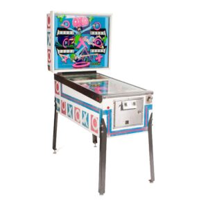
OXO Pinball Machine

Rock Pinball Machine
Austin Powers Pinball Machine
Bugs Bunny’s Birthday Ball Pinball Machine

Cosmic Carnival Pinball Machine
Dale Earnhardt Jr Pinball Machine

Led Zeppelin Pro Pinball Machine
- Jersey Jack
- Show Spoilers
- Night Vision
- Sticky Header
- Highlight Links
Follow TV Tropes
http://tvtropes.org/pmwiki/pmwiki.php/Pinball/StarTrekDataEast
Pinball / Star Trek (Data East)
Edit locked.

Scotty: "We have full power! Use the transporter!"
Star Trek is an arcade pinball game by Data East , the second official Trek table . Designed by Ed Cebula and Joe Kaminkow , it was released in 1991 for the 25th anniversary of Star Trek: The Original Series .
Appropriate for a Milestone Celebration pinball, the playfield is filled with iconic props from the television show, such as the Guardian of Forever, the transporter, the Doomsday Machine, and a bank of Dilithium Crystals. Playfield images spotlight key characters and scenes, including Lt. Uhura's evil counterpart, Commander Pike, an armful of Tribbles, and an assortment of Klingons, Andorans, Romulans, and Gorn . But the most eye-catching aspect of this pinball is in the backglass, which shows Captain Kirk leading an Away Team on the transporter pad. At key points during a game, the transporter will activate and beam away the party — and only judicious shots to the moving Master Crystal will re-energize the transporter to bring them back. Original voice clips from James Doohan give player directions, supplemented with sound effects from the TV show.
Star Trek is considered to be one of the better pinball machines from Data East, though cynics will argue that's not saying much . While the rules are fairly simple and won't challenge pinball experts, the gameplay is fast and balanced, and the excellent use of the license adds to the fun.
This game was used as the basis for "Joel Silver: The Pinball", a unique vanity table for the famous Hollywood film producer. The game replaced the Dilithium Crystals with popcorn, and included voice clips from both Silver himself and his friends and coworkers. The game resided at Silver's Warner Bros. reception area for several years.
Star Trek (Data East) demonstrates the following tropes:
- Beard of Evil : On the Klingons.
- Beehive Hairdo : Yeoman Rand has one of these.
- Bridge Bunny : Janice Rand.
- Continuity Cameo : The playfield is filled with numerous Trek characters from the original series.
- Eat Me : Invoked by shooting into the Doomsday Machine.
- Evil Twin : The Mirror Universe Uhura from "Mirror, Mirror" , of course.
- Green-Skinned Space Babe : A green Orion slave girl can be seen in the upper-left playfield.
- Planet Eater : The Doomsday Machine.
- Plot Coupon : Collect Dilithium crystals to activate the transporter, and shooting the transporter within the allotted time starts multi-ball.
- Shirtless Scene : Sulu, reprising his fencing scene from "The Naked Time" .
- Skill Shot : Press the launch button at the right time to shoot a spaceship flying across the dot matrix display.
- Soundtrack Dissonance : The main theme music is a fast-paced thumping rock beat that conflicts abruptly with the Trek license. This is due to the fact on how Brian Schmidt composes his BSMT2000-based music.
- Spelling Bonus : S-T-A-R-T-R-E-K, appropriately enough.
- Video Mode : Enemy Alert, which is simply the Skill Shot minigame except 10 times in a row.
Alternative Title(s): Star Trek 1991
- Batman (Data East)
- Creator/Joe Kaminkow
- Lethal Weapon 3
- The Simpsons (Data East)
- Creator/Data East
- Star Wars (Data East)
- Star Trek: The Next Generation
- Star Trek (Bally)
- Physical Pinball Tables
- Star Trek (Stern)
- Licensed Pinball Tables
Important Links
- Action Adventure
- Commercials
- Crime & Punishment
- Professional Wrestling
- Speculative Fiction
- Sports Story
- Animation (Western)
- Music And Sound Effects
- Print Media
- Sequential Art
- Tabletop Games
- Applied Phlebotinum
- Characterization
- Characters As Device
- Narrative Devices
- British Telly
- The Contributors
- Creator Speak
- Derivative Works
- Laws And Formulas
- Show Business
- Split Personality
- Truth And Lies
- Truth In Television
- Fate And Prophecy
- Edit Reasons
- Isolated Pages
- Images List
- Recent Videos
- Crowner Activity
- Un-typed Pages
- Recent Page Type Changes
- Trope Entry
- Character Sheet
- Playing With
- Creating New Redirects
- Cross Wicking
- Tips for Editing
- Text Formatting Rules
- Handling Spoilers
- Administrivia
- Trope Repair Shop
- Image Pickin'
Advertisement:

- Pinball Repair & Pinball Servicing
- Work Samples
- Used Pinball Machines For Sale
- Pinball Machine Rentals

Contact Us Today
630-220-8478
[email protected]
Authorized Distributor & Parts Retailer:
- Spooky Pinball
- American Pinball
- Chicago Gaming
- Multi Morphic
- Pinball Machines
- Pinball Restoration
- Our Pinball Restoration Process
- Pinball Machine Work Samples
- Pinball Machines For Sale
- Pinball Machine Blog
- Internet Pinball Machine Database
Pinball Links
- Jersey Jack Pinball
- Pinball Geek
- Pinball Life
- Pinball Repair Guides
- Pinball Restoration Tips
- Stern Pinball
- Sales – Accessories
- Sales – Parts
- Sales – Pinball
- Sales – Video Games
- Uncategorized
Star Trek 25th Anniversary Data East Pinball Game – $2,995
Star Trek! What a great theme and franchise! This is the 2nd in the series…. The first was the bally star trek in 1979, and in 1993 was Star Trek The Next Generation. Game is designed by Joe Kaminkow , Ed Cebula . Lots of cool ramp shots, all the original voices from the characters in the TV series. Lots of drop targets and other stationary targets to shoot at. It also has 3 pop bumpers, ramp diverters, a moving target, 2 flippers, and 2 slingshots. The game also has 2 multi ball modes… a 2 ball and a 3 ball multi ball. The neatest thing in the game is that it has a working transporter where the characters fade in and out! Lots of fun for the whole family. A Great Xmas present! This one is in exceptional condition. Always been in a smoke free environment. This game will accomodate up to 4 players. Fully shopped out / restored and working 100%. Very family friendly game. Ready for delivery or ready to ship.
Comments are closed.
Copyright Endless Pinball 2024
Star Trek, Data East
No products in the cart.
- USD $ CAD $
- Mini Playfields
- Backglasses
- Plastics Upgrade Kits
- Speaker Skins
- Miscellaneous
- The Process
- How To Purchase
- Completed Projects

$ 949.00 USD
DataEast STAR TREK Short-Run Reproduction Playfields from CPR
AVAILABLE FOR THE FIRST TIME IN THE HOBBY EVER !! New release for May 2022 ! Depending on sales results, we’ll try to keep these in standard rotation from now on. 5-layer polyeurethane clearcoated. Complete gallery with close-ups for your consideration. As with all our small-batch runs, consider these “get them while they’re avail able!”
PLEASE NOTE: “Hot” Neon pigments were used in the pink & green silkscreen inks of the originals. This is not possible on modern digital reproductions. So please make sure you look at the Gallery images to make sure you are happy with the colors.
DON’T FORGET THE DISCOUNTS! OPTIONAL PLAYFIELD ADD-ONS: For any playfield shipment, you may add any backglass, plastics set, and/or topper into the same Cart, and receive Bundle Discounts on those items! They don’t even have to match the selected playfield(s) any more! Take advantage of combined shipping, and save big compared to buying and shipping separately later on. Discounts apply automatically in your Cart.
Username or email address *
Remember me
Lost your password?
Email address *
COMMENTS
Internet Pinball Machine Database: Data East 'Star Trek'. Star Trek / IPD No. 2356 / October, 1991 / 4 Players. [ Submit Changes ] Average Fun Rating: 7.4 /10 ( 52 ratings/34 comments ) [ Add Your Rating! Manufacturer: Data East Pinball, Incorporated (1986-1994)
Find out everything about Star Trek (Data East, 1991) pinball machine; General game details, ratings and reviews, photos, videos, high scores, places to play and find machines currently for sale on our market place. ... Data East Star Trek Star Trek is a pinball machine from October 1991, manufactured by Data East USA, Inc. Tags: LICENSED SCI ...
A great Data East pinball with a theme from the original Star Trek. Side art features the original Enterprise NCC-1701. Head Artwork. To boldy go where no man has gone before. A closeup shot of the start button and front leg. A classic Pinball Glass with Captain Kirk, Spock and others. Coin Door and front artwork. Full playfield view.
Star Trek is a Pinball by Data East (circa 1991). Information about it's history and background, photos, repair help, manuals, for sale and wanted lists, and census survey is brought to you by The International Arcade Museum at the Museum of the Game.
Star Trek 25th Anniversary (Data East 1991) b2s with full dmd ... VPUniverse is a site dedicated to digital pinball simulations and anything pinball in general. Our primary focus is on Digital Pinball formats including Visual Pinball, Future Pinball, and many more pinball simulators. All content is provided on this site for free to all ...
Star Trek (25th Anniversary) (Data East 1991) About VPUniverse. VPUniverse is a site dedicated to digital pinball simulations and anything pinball in general. Our primary focus is on Digital Pinball formats including Visual Pinball, Future Pinball, and many more pinball simulators. All content is provided on this site for free to all registered ...
Here is a fully refurbished Star Trek Data East we completed. The artwork on this game is amazing. This is one of Data East Pinball's best playing games. To ...
The Star Trek Pinball machine was created by Data East in 1991. The machine's artwork prominently featured the main characters of Star Trek: The Original Series. The game also featured digitized audio clips of James Doohan as Montgomery Scott. Star Trek at The Internet Pinball Database
Data East Star Trek® (25th Anniversary Pinball) manual.This file was originally downloaded from the IPDB (The Internet Pinball Database) website. ... Data_East_Star_Trek_Manual Identifier-ark ark:/13960/t9868jf3r Ocr ABBYY FineReader 11.0 Ppi 600 Scanner Internet Archive HTML5 Uploader 1.6.3 ...
Find out everything about Star Trek (Data East, 1991) pinball machine; General game details, ratings and reviews, photos, videos, high scores, places to play and find machines currently for sale on our market place.
Brief tutorial of scoring strategies for Data East Star Trek 25th Anniversary pinball.
Star Trek 25th. Anniversary Edition pinball, produced by Data East in 1991. This has the functional "transporter" feature in the backglass, which is a very cool toy. Note: The display / speaker panel has been signed by William Shatner. Note: The photo galley shows the CPU missing. I have the original and that is what…
Find out everything about Star Trek (Data East, 1991) pinball machine; General game details, ratings and reviews, photos, videos, high scores, places to play and find machines currently for sale on our market place. ... Data East Star Trek Pinside Rating. This game received 91 approved Pinsider ratings and currently rates 7.617 / 10. 7.617.
Data East/Sega pinball used a board set with minor differences from 1987 to 1995. This boardset, like most hardware of this generation, is very derivative of Bally/Williams System 11 hardware. Data East Standard DMD Board Set, this from a Star Wars. The following boards are typical of what you will find in a Data East backbox.
Delivery and Installation (Outside Service Area): $999.99. (Prices above are for shipping within the continental US only. For shipping anywhere else please call: (941) 281-2987) Star Trek pinball was released by Data East in 1991 for the 25th anniversary of Star Trek: The Original Series. Order now!
Find out everything about Star Trek (Data East, 1991) pinball machine; General game details, ratings and reviews, photos, videos, high scores, places to play and find machines currently for sale on our market place.
Star Trek is an arcade pinball game by Data East, the second official Trek table.Designed by Ed Cebula and Joe Kaminkow, it was released in 1991 for the 25th anniversary of Star Trek: The Original Series.. Appropriate for a Milestone Celebration pinball, the playfield is filled with iconic props from the television show, such as the Guardian of Forever, the transporter, the Doomsday Machine ...
Star Trek 25th Anniversary Data East Pinball Game - $2,995. Star Trek! What a great theme and franchise! This is the 2nd in the series…. The first was the bally star trek in 1979, and in 1993 was Star Trek The Next Generation. Game is designed by Joe Kaminkow , Ed Cebula. Lots of cool ramp shots, all the original voices from the characters ...
Show per page. Star Trek 25th Anniversary CPU Game/Display Rom 3.00 (Pinballcode) €19.95. Add to Cart. Star Trek 25th Anniversary ColorDMD. €539.99. Add to Cart. Star Trek 25th Anniversary Apron Decal Set. €19.95.
Star Trek, Data East. Filter . Sorting. Close filters . items found . Immediately available . Price . from 0 to 549 . items found . 1 From 3. Products per page. No results were found for the filter! ... Flipper Board for Sega/Data East pinball machines with 2 Flipper. Ref. Part No.: 520-5233-00, 520-5080-00 Compatible Games: Adventures of Rocky ...
Find out everything about Star Trek (Data East, 1991) pinball machine; General game details, ratings and reviews, photos, videos, high scores, places to play and find machines currently for sale on our market place. ... PPW WTB: Star Trek Data East 25th Sound Board 520-5050-00 Rev-C By Yoak (1 year ago) - Last post 1 year ago. 1 1 yr. MFS Ended
Star Trek (DataEast) Playfield. $ 949.00 USD. DataEast STAR TREK. Short-Run Reproduction Playfields from CPR. AVAILABLE FOR THE FIRST TIME IN THE HOBBY EVER !! New release for May 2022 ! Depending on sales results, we'll try to keep these in standard rotation from now on. 5-layer polyeurethane clearcoated. Complete gallery with close-ups for ...
Data East made 2 machines that used chase rope light, Start Trek and Hook. Both can be trouble to repair and both have a fairly high failure rate. ... Star Trek 25th Anniversary Pinball (Data East) - ROM Upgrade. Matt's Basement Arcade $ 30.00 Electronics. D/E Pinball Power Supply Capacitor Rebuild Kit 520-5047-00. Yorktown Arcade Supply ...