- Online Training
- Access Your Courses
- Group Registration
- The Complete Relay Testing Handbook Series
- Book Extras
- Your Digital Downloads
- Hands-On Training Class Information
- Download Our Relay Training Brochure
- TechTalk (Our Blog)
- Add Your Post to TechTalk
- We Need Your Help!
- Why Choose Valence?
- About Chris Werstiuk
- Testimonials
- Contact Valence
- Subscribe to our Mailing List
- Your Shopping Cart
- The Relay Testing Handbook
- Your Account Info
No products in the cart.

Direct Transfer Trip and Direct Under-Reaching Transfer Trip Schemes Video
We’re continuing our end-to-end testing series by looking at the two simplest communication-assisted trip schemes used. Watch this Direct Transfer Trip and Direct Under-Reaching Transfer Trip Schemes Video to learn more about these two schemes. You can read the transcript below the video.
If you haven’t watched Understanding Line Distance protection (21) , watch it first.
Direct Transfer Trip and Direct Under-Reaching Transfer Trip Schemes Video Transcript
Welcome to the third video in our End-to-End Testing series. In this video we’re going to look at Direct Transfer Trip schemes or DTT schemes and then we’re going to look at Direct Under-Reaching Transfer Trip schemes (or DUTTs).
This video is part of a series. If you have not watched Understanding Line Distance Protection, the link is on the screen right now, then go watch that video first, so you get the foundation of what we’re going to talk about in this video so we don’t have to keep repeating ourselves over and over again. Let’s get started.
The first thing that we want to look at is the DTT, or the Direct Transfer Trip scheme and we don’t have a fancy animation built for that one because it’s really simple. What you’re looking at is an excerpt from The Relay Testing Handbook: End-to-End Testing and a DTT scheme is really just sending a signal from one side to the other. That’s what the direct part of Direct Transfer Trip stands for.
There is no reason for you to pull out your fancy GPS test equipment in order to test this scheme. The testing procedure for this scheme is very simple. Put one body at Relay 1, another body at Relay 2, get on your cell phones, and have Person 1 push the Trip button. The Trip button will go to the transmit of Relay 1. It’ll then send a signal to Relay 2. Relay 2 will receive that signal and open the breaker. Body Number 2 pushes their button and then the reverse should happen and Breaker Number 1 should open. Now it doesn’t have to be a trip contact. It could also be a breaker status contact or anything else, but it usually is something very simple. So there’s no reason for fancy test equipment.
The next scheme that we want to look at is the Direct Under-Reaching Transfer Trip and just like the Direct Transfer Trip scheme, Direct means that there’s no communication happening between the two relays. One relay sends the command to the other relay. So once again, there’s no reason for you to get out all your fancy GPS test equipment, because it’s a really simple test.
The top shows the standard distance protection scheme with no communication and the bottom shows the DUTT scheme with communication so that we can see what we’re gaining when we have the communication assisted trip schemes. And the first thing I’m going to do is, I’m going to put the fault really close to Relay 1. Now if you’ve watched the previous videos, or if you have any understanding of Distance Protection at all, you will know immediately that Relay 1 is going to see Zone 1 and it’s going to see Zone 2. Relay 2, because the fault is still on the line is going to see Zone 2. The difference between the standard distance scheme and the DUTT scheme is that the standard scheme Relay 1 is going to operate instantaneously and Relay 2 is going to operate after a 20 cycle delay, but if you look at the DUTT scheme, Zone 1 still trips the Relay 1 breaker immediately, but it also sends a command to the other side telling it to open as fast as it can, which is typically under 3 cycles, depending on communication delays. The DUTT scheme has saved us 17 cycles.
Now if I move the fault to the other side, you can see that the fault is now close to Relay 2 and the opposite is going to happen. Relay 2 is going to see Zone 1 and Zone 2. Relay 1 is going to see Zone 2 and the breaker connected to Relay 2 is going to open instantaneously and then we’re going to have that 17 cycle delay between the opening of the breaker on Relay 1.
If I go outside of the zone, this relay is going to see Zone 3 and Relay 2 is going to see Zone 2. Zone 2 has a faster time delay than Zone 3, so the Zone 2s are going to operate in the same amount of time. So the DUTT scheme gives us the benefit of saving 17 cycles for faults on the line and then giving us our normal backup protection for faults outside of the line. That 17 cycles might not seem like a big deal, but it is forever in electrical terms and there have been some papers presented that show that the longer a fault stays on the system, the more unstable it gets which is a big deal today.
If you like this animation, and you want to play with it some more, you can click the link below to go to our website and you can play with this animation or all the other ones that we’ve created for the communication trip schemes. I hope you’ve enjoyed this video. If you did, please subscribe to our channel, like, and also look for our next video, which should be about, Permissive Under-Reaching Transfer Trip schemes or PUTT schemes. We look forward to seeing you then, thank you.
Did you like this post?
You can share it with these links:
About the Author
Valence Announcements
Chris is an Electrical Engineering Technologist, a Journeyman Power System Electrician, and a Professional Engineer. He is also the Author of The Relay Testing Handbook series and founder of Valence Electrical Training Services. You can find out more about Chris here .
Read More Articles:
Valence will be at the NETA PowerTest 2016 Conference in Fort Worth, TN
I Want to Know How a High Impedance Differential Scheme Works
Leave a Reply
Your email address will not be published. Required fields are marked *
Application Notes:
Direct transfer trip: three simple solutions to connect with fiber, t1 or ethernet.
Direct Transfer Trip (DTT) is a teleprotection scheme that involves sending trip signals from one location to another via a telecommunications transport, such as a phone line, radio, or fiber optics. It is commonly used for substations to detect substation faults and create lines of isolation while the faults are under investigation.
Because DTT signals have commonly been carried over leased telephone lines, many customers in industries such as utility and railway seek alternative DTT solutions as telecom providers either discontinue their leased line services or dramatically raise their prices to keep them.
In this application note, we explore three simple, drop-in solutions as a replacement for leased telephone lines in DTT systems, providing more cost-effective and reliable connectivity.
DTT Over a Leased Telephone Line (Conventional Method)
In this Direct Transfer Trip setup, a DTT relay is installed at both ends of a leased telephone line. The DTT relays are also each connected to circuit breakers, usually via fiber or pilot wire. This is represented by the diagram seen here:
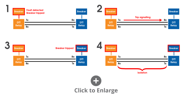
In simple terms, when the DTT relay on the left (for example) detects a fault occurring within the substation, it trips the circuit breaker on the right (shown in blue). At the same time, it transmits a signal to the DTT relay on the right (shown in blue), which trips the circuit breaker on the left (shown in orange), creating a line of isolation between the two circuit breakers (shown in black).
When connecting the DTT relays over a leased telephone line, the setup might be represented as follows:
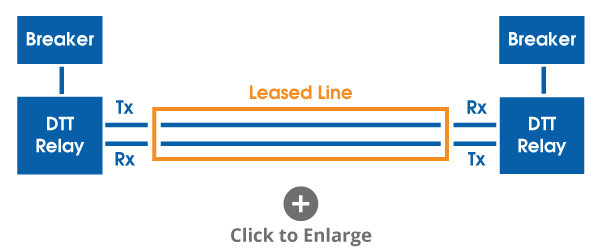
The leased line passes analog tones that ensure the DTT relays isolate the section of line with a fault present.
Three Alternative Solutions to Using Leased Lines
In situations where customers are looking to replace their leased lines or a leased line is otherwise unavailable, there are alternative solutions that TC Communications can provide. The three most common alternative transport methods for DTT are:
For these three methods, we use three main products for connecting over fiber, T1, and Ethernet, respectively:
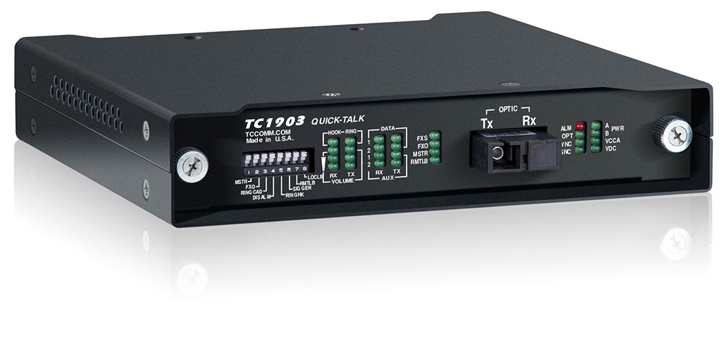
TC1903 : This Fiber Optic Phone/Analog Extender (with Bidirectional Single Fiber)* comes in a small, modem-sized form factor and extends analog and POTS telephone service to remote sites, in this case serving as an analog extender. It extends a 600 Ohm two- or four-wire line over fiber and is compatible with most PBXs or Key Systems.
*The TC1901 can be used in place of the single-fiber TC1903 for applications using dual fiber.
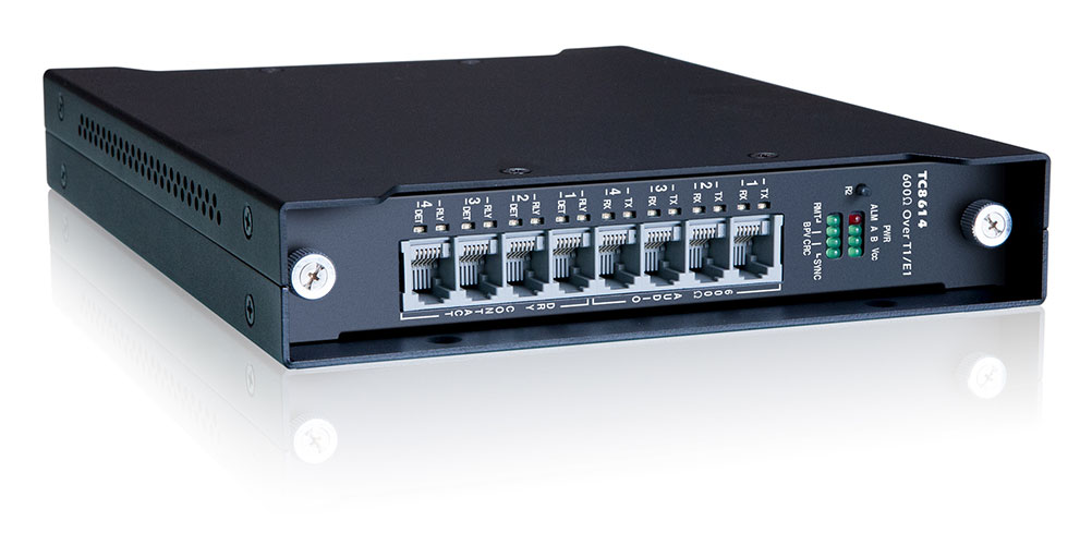
TC8614 : This 4 Channel 600 Ohm Analog and Dry Contact-over-T1/E1 Multiplexer, part of our Mini Channel Bank family, is typically used to link or extend various 600 Ohm analog, audio, and intercom devices (e.g. FSK modems, E&M, teleprotection relay controllers, etc.), and dry contacts over existing T1/ E1 links. It is also used as a backup network to ensure business continuity.
TC3846-6 : This 2W/4W E&M 600 Ohm over IP Gateway is one of our most popular JumboSwitch® products. It links or extends up to four channels of 600 Ohm 2 or 4-wire analog and dry contacts across Layer 2/3 Ethernet/IP, CE, or MPLS networks.
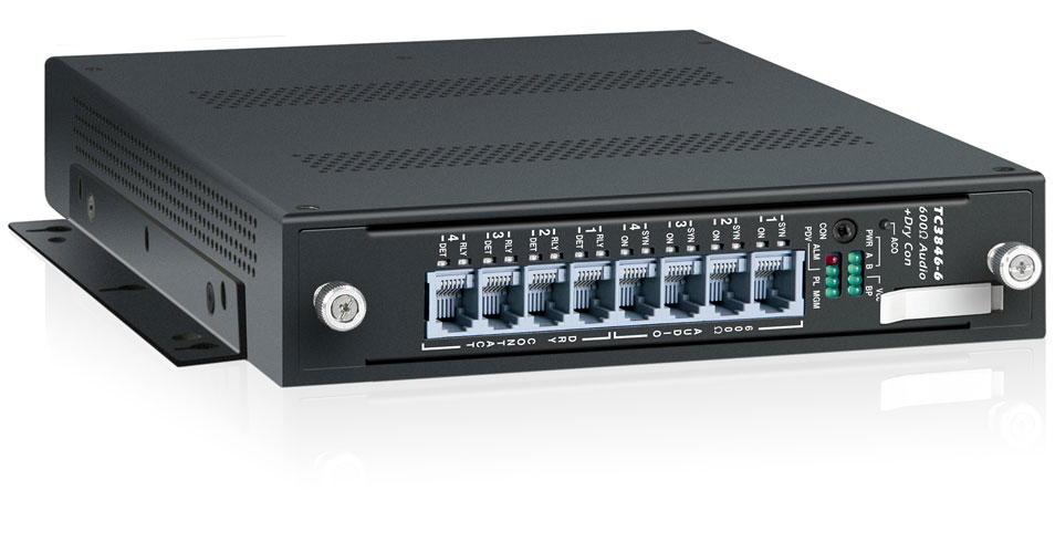
Next, we will take a look at three similar drop-in replacement solutions for DTT using these products.
Connecting Over Fiber Using the TC1903
In this application, a leased line is replaced by two TC1903 cards that are connected via single bi-directional fiber.
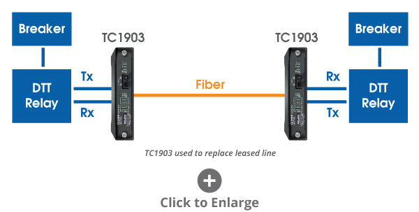
The DTT relays on each end connect to the TC1903 cards via the typical transmit and receive ports. With this setup, the DTT relays operate exactly as they would if they were still connected to a four-wire analog or leased line circuit, providing a fast and reliable means of transmitting and receiving DTT signals to trip the circuit breakers when a fault is detected.
For customers that have the capability or preference to use dual fiber instead of single fiber, the exact same effect can be achieved using two TC1901 cards instead.
Connecting Over T1 Using the TC8614
In this application, in place of a leased line, two TC8614 cards connected over a T1 line. It is another drop-in replacement that functions in much the same way as the TC1903 application over fiber.
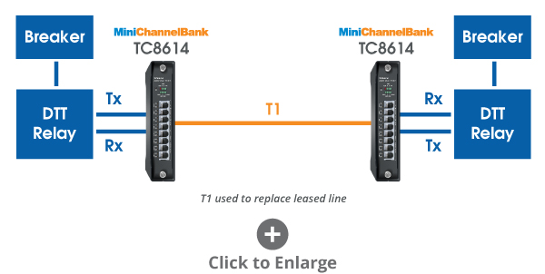
Each DTT relay connects to a TC8614 card via the Tx and Rx ports, enabling fast and reliable transmission and receiving of DTT signals when a fault is detected, tripping both circuit breakers and creating an isolated line between them.
Many telecom providers discontinuing their leased lines, such as Verizon and AT&T, are now offering T1 services as a generally lower-cost alternative. When T1 lines are available, the TC8614 can seamlessly provide the solution.
Connecting Over Ethernet Using the TC3846-6
In this application, two TC3856-6 JumboSwitch cards are connected over Ethernet/IP to extend a circuit between two DTT relays.
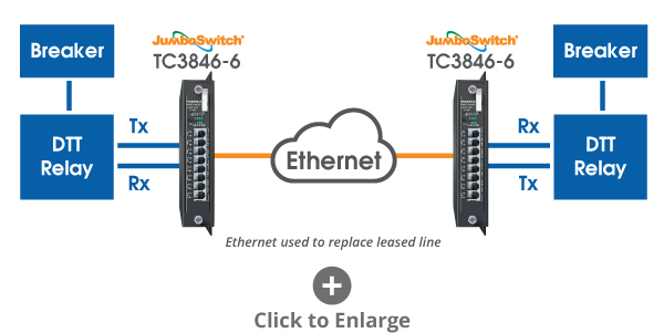
Each DTT relay connects to a TC3846-6 card via the Tx and Rx ports, enabling it to transmit and receive DTT signals to and from the other relay. One, two, or four channels may be used over 2 or 4-wire analog over Ethernet.
This is an excellent choice for sites where Ethernet connectivity is already present and due to the JumboSwitch connecting with extremely low latency, it is fully compatible with all DTT applications.
A Customer Example
A major greater Chicago metropolitan transit organization needed to connect DTT relays between the sites.
To achieve this, we installed a pair of TC1903 cards at each site (26 total) and connected them via 12 strands of single-mode fiber to link the 13 sites together in a chain fashion. (For illustration purposes, only three sites will be shown in the diagram below).
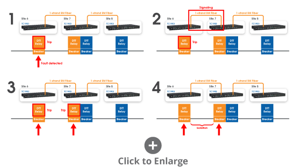
Let's take a look at three of their sites and how they work. We have a power line with breakers providing power to transit locomotives between site six and seven.
We have a single strand of fiber connecting two DTT relays via two TC1903s. If the breaker at site 6 is triggered, the signal will reach the breaker at site 7 over fiber and cause an isolation.
The same event can occur only between site 7 and 8 and so on.
With average leased line costs exceeding $1,500 a month and even as high as $10,000 a month, more customers are seeking alternative solutions for Direct Transfer Trip applications. The three solutions covered here over dedicated dark fiber, T1, and Ethernet connectivity provide customers with the flexibility to use what is available to them or reduce costs through leased line replacement.
Each of the TC Communications products used in these solutions is covered by a five-year warranty and available in an extreme temperature version with an operating range between -40 to 80 degrees Celsius (-40 to 176 degrees Fahrenheit), making them ideal for withstanding harsh weather conditions, helping to maintain reliable in DTT teleprotection.

JumboSwitch® Multi-service Ethernet Platform

2W/4W E&M 600 Ohm and Dry Contact over IP TC3846-6

"Quick-Talk" Asynchronous RS-232 or Fiber Telephone Extender (Supports 1-Fiber Bi-Directional) TC1903

2W/4W E&M 600 Ohm and Dry Contact over T1/E1 TC8614

Rail Networks

Leased Line Replacement

Teleprotection over IP
Interested in similar content? Subscribe to our mailing list.
Direct Transfer Trip (DTT) leveraging redundant cellular communication channels
Ieee account.
- Change Username/Password
- Update Address
Purchase Details
- Payment Options
- Order History
- View Purchased Documents
Profile Information
- Communications Preferences
- Profession and Education
- Technical Interests
- US & Canada: +1 800 678 4333
- Worldwide: +1 732 981 0060
- Contact & Support
- About IEEE Xplore
- Accessibility
- Terms of Use
- Nondiscrimination Policy
- Privacy & Opting Out of Cookies
A not-for-profit organization, IEEE is the world's largest technical professional organization dedicated to advancing technology for the benefit of humanity. © Copyright 2024 IEEE - All rights reserved. Use of this web site signifies your agreement to the terms and conditions.

Substation Design | Power System Analysis
Basics of Pilot Relaying & Application Considerations For Transmission Line Protection
Pilot relaying refers to any relaying scheme employing a communication network between relays, at different substations, to transmit “trip or don’t trip” signal. The intent here is to trip the circuit breakers as fast as possible.
In the past, the relays communicated over the copper wire that directly tied them. These days we possess other options, described later in this article.

Rationale for pilot relaying
- Faster fault clearing time
- When compared to no pilot channel, the protection scheme exhibits increased security and dependability
- Enables high speed reclosing
- Simplifies relay coordination
Communication channel for pilot relaying
The relays utilize communication facilities described below.
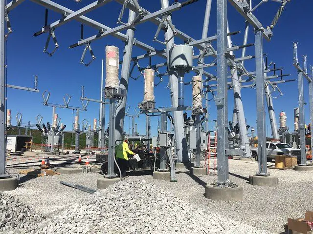
Power line carrier (PLC)
The communication path is the power line itself. A pilot relay, capable of generating a high-frequency carrier signal, couples the “message” to the high voltage line via a line-tuner and capacitor-coupled voltage transformer.
The pilot relay generates either
- On/Off carrier signal- (amplitude modulation) think of it as infrequent pings.
- Frequency Shift Keying (FSK) carrier signal – (frequency modulation) think of it as a persistent dial-tone you hear on the phone.
Fiber optic cable
Specific relays, fitted with high wattage laser, communicates through a single-mode fiber.
The fiber specified is either
- OPGW on transmission towers
- ADSS cable on distribution pole or underground.
The fiber optic cable is directly hooked to the protective relays on either end of the line. When forming a network of relays, located at various substations, connect them using a JungleMUX SONET multiplexer.
Microwave radio
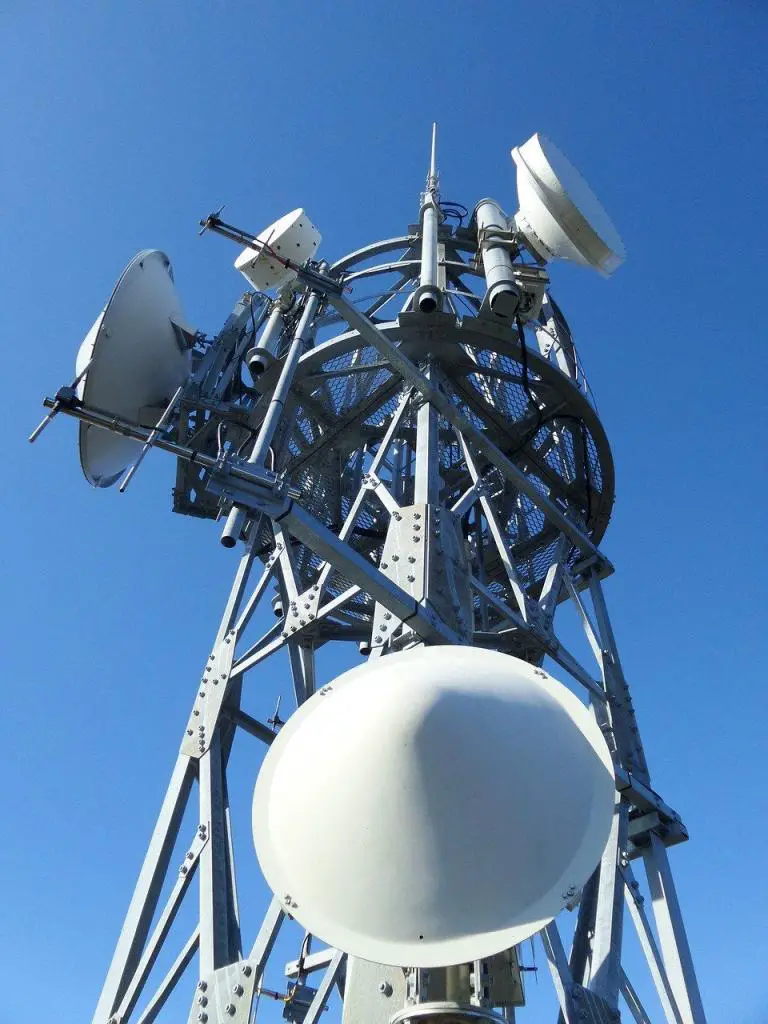
If the line of sight between the two substations appears clear and there are other towers for the signal to hop until it reaches its destination, then install a microwave tower.
The microwave radio signal generated is either
- Analog signal
- Digital signal
Lately, analog microwave radio for transmission protection is being retired and upgraded with the digital one.
Plain old telephone system (POTS)
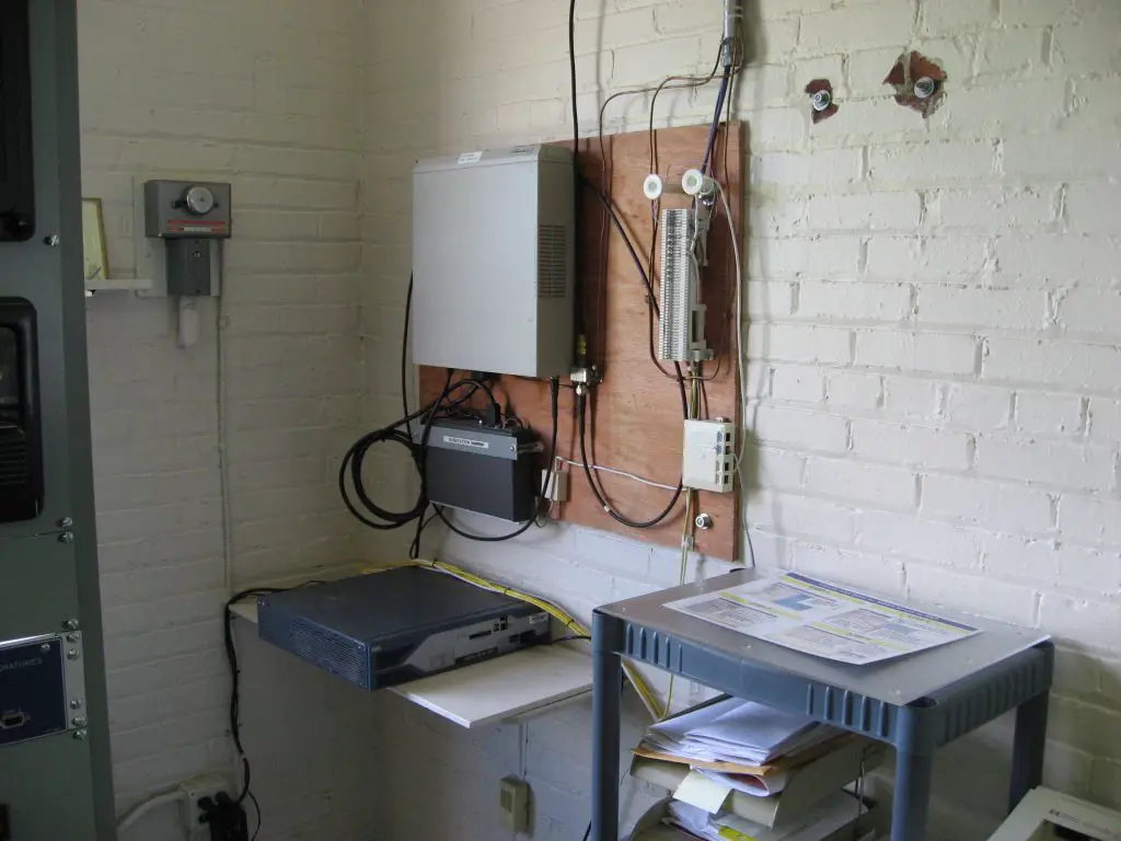
Relay communication may also take place over lines leased from local telephone company.
Much like a power line carrier, protective relays can transmit a tone over the line whose modulation (higher or lower) indicates a fault condition.
POTS facilities utilize either
Lately, analog POTS for transmission protection is being retired and replaced in place of other communication technology. Digital service continues to survive because it allows field crews to chat with a load dispatcher, and it maintains 911 service.
Pros and cons of communication channels for pilot relaying
Ignoring the latency of transmitters and receivers, every communication channel discussed above possesses minimal signal transmission delay. Once the signal gets coupled or transmitted, it travels roughly at the speed of light. For this reason, even something like POTS gets used for direct transfer trip – a high-speed protection scheme.
Low latency is one aspect, but bandwidth is another. Specific protective schemes, like line current differential, require high bandwidth to accommodate significant data flow between relays. Both fiber and digital microwave radio can support this application, unlike PLC and POTS.
No communication channel can elude signal attenuation.
- With PLCs, attenuation may occur due to the corona effect, system disturbances, line switching, storm effects, etc. Attenuation can also occur at the point of coupling as seen in figure 40 in the linked paper.
- With fiber, incorrect splicing, poor terminations, etc. causes light reflection. However, with fewer external factors impacting the signal, this channel stands-out among others.
- With microwave radio, weather condition distorts signal arriving at the receiver.
- With POTS – radio interference, incorrect splicing, poor terminations, etc. diminishes signal.
Transmission line protection schemes employing communication channel
Phase angle comparison.
Compares the phase angle of fault current entering and leaving the zone of protection.
If currents are in-phase (entering and leaving the zone), then no tripping occurs on account of the fault being external. However, fault currents 180deg out-of-phase appears internal, and tripping occurs.
Communication channel: PLC, metallic pair, leased telephone line, digital microwave, or fiber optics.
Current differential
Compares magnitude and phase angle of current entering or leaving the zone of protection.
Similar to the phase angle comparison scheme, external faults are ignored whereas internal faults are acted upon.
Communication channel: Fiber optics or digital microwave.
Directional comparison schemes
Works using step distance protection offered by line relays.
To speed up tripping, the following communication/modulation schemes are applied.
- Directional comparison blocking scheme (DCB)
- Permissive overreaching transfer trip scheme (POTT)
- Permissive under-reaching transfer trip scheme (PUTT)
- Directional comparison un-blocking scheme (DCUB)
Communication channel: PLC (for DCB & DCUB only), leased telephone line, digital microwave, or fiber optics.
Personal philosophy, availability of channel, and experience of operating the protected line dictates which protection scheme gets implemented. When a fiber channel exists, the current differential scheme is the obvious choice. Otherwise, existing power lines can be used to administer any one of the directional comparison schemes. Substations located in remote locations can rely on PLC and as a back-up, on microwave radio. As you dig deeper into modulation schemes, you will understand why some cannot be implemented over PLC and must use other channels.
This article is the first in a series, covering the essentials on pilot relaying and pilot protection schemes. If interested, dig deeper below.
- Directional Comparison Blocking Scheme (DCB)
- Permissive Overreaching Transfer Trip Scheme (POTT)
- Directional Comparison Un-Blocking Scheme (DCUB)
- Direct Transfer Trip Scheme (DTT) (This is technically not a pilot scheme but requires a pilot channel)
4 thoughts on “Basics of Pilot Relaying & Application Considerations For Transmission Line Protection”
Great article, learning a ton from you!
Very easy to understand. To the point, no fluff. I like it! Thanks!
Very good, simple explanation of transmission line relaying, DTT, POTT and DCB.
I love your write up because it’s quick and to the point for those who have some knowledge of the systems, it gives a good overview.
Leave a Comment Cancel Reply
Your email address will not be published. Required fields are marked *
Aleen Mohammed
Connect with me
- Skip to content
- Skip to search
- Skip to footer
Direct Transfer Trip Use Case over Cellular for DER Sites White Paper
Available languages, download options.
- PDF (1.1 MB) View with Adobe Reader on a variety of devices
Bias-Free Language
The documentation set for this product strives to use bias-free language. For the purposes of this documentation set, bias-free is defined as language that does not imply discrimination based on age, disability, gender, racial identity, ethnic identity, sexual orientation, socioeconomic status, and intersectionality. Exceptions may be present in the documentation due to language that is hardcoded in the user interfaces of the product software, language used based on RFP documentation, or language that is used by a referenced third-party product. Learn more about how Cisco is using Inclusive Language.
Table of Contents
Wireless technologies offer an alternative solution to enable communications for the various distribution grid use cases. These technologies are especially useful in providing connectivity to the various Distributed Energy Resources (DER) assets and local distribution substations.
Typically, protection equipment will operate locally and does not use data from other devices to operate. However, some schemes do use communications for normal operations. One such scheme is Direct Transfer Trip (DTT), where upstream substations need to trip DER assets off the network in the event that the substation feeder breaker opens.
Traditionally, DTT signals were sent between substations and remote Distributed Generation (DG) sites using leased telephone lines. DTT systems are installed for critical high-speed tripping of circuit breakers on either side of a feeder interconnecting substations or between the substation breaker and a DG site’s station equipment.
Cisco and Verizon have undertaken work to validate the use of cellular networks to provide a flexible and easy-to-deploy connectivity solution to provide the backhaul technology. Today, cellular networks are reliable and can be deployed at a low cost compared to dedicated fiber.
The focus of this work was on leveraging standards-based and scalable communication technologies to provide encrypted connectivity between sites while supporting the transport of Layer 2 multicast non routable IEC 61850 GOOSE messaging in peer-to-peer topologies. Plus, the same solution will also natively allow Supervisory Control and Data Acquisition (SCADA) data to be transported within the same encrypted tunnels.
It was important to evaluate the latency, jitter, and packet loss applicable to these private and commercial cellular networks when applied to the DTT use cases:
● IEEE 1547-2018 states that for DTT operation, DER assets should be disconnected within 2 seconds (however, the communications budget for this operation is much smaller).
● Customer requirements for the actual communications budget range from 40 to 80 ms.
Cisco provided the Cisco Catalyst ™ 1101 Rugged Router (IR1101), used widely in distribution automation networks today, with plug-in cellular modules to support the various commercial and private spectrum bands, including Citizens Broadband Radio Service (CBRS), Anterix, and commercial bands (such as FirstNet and First Responder).
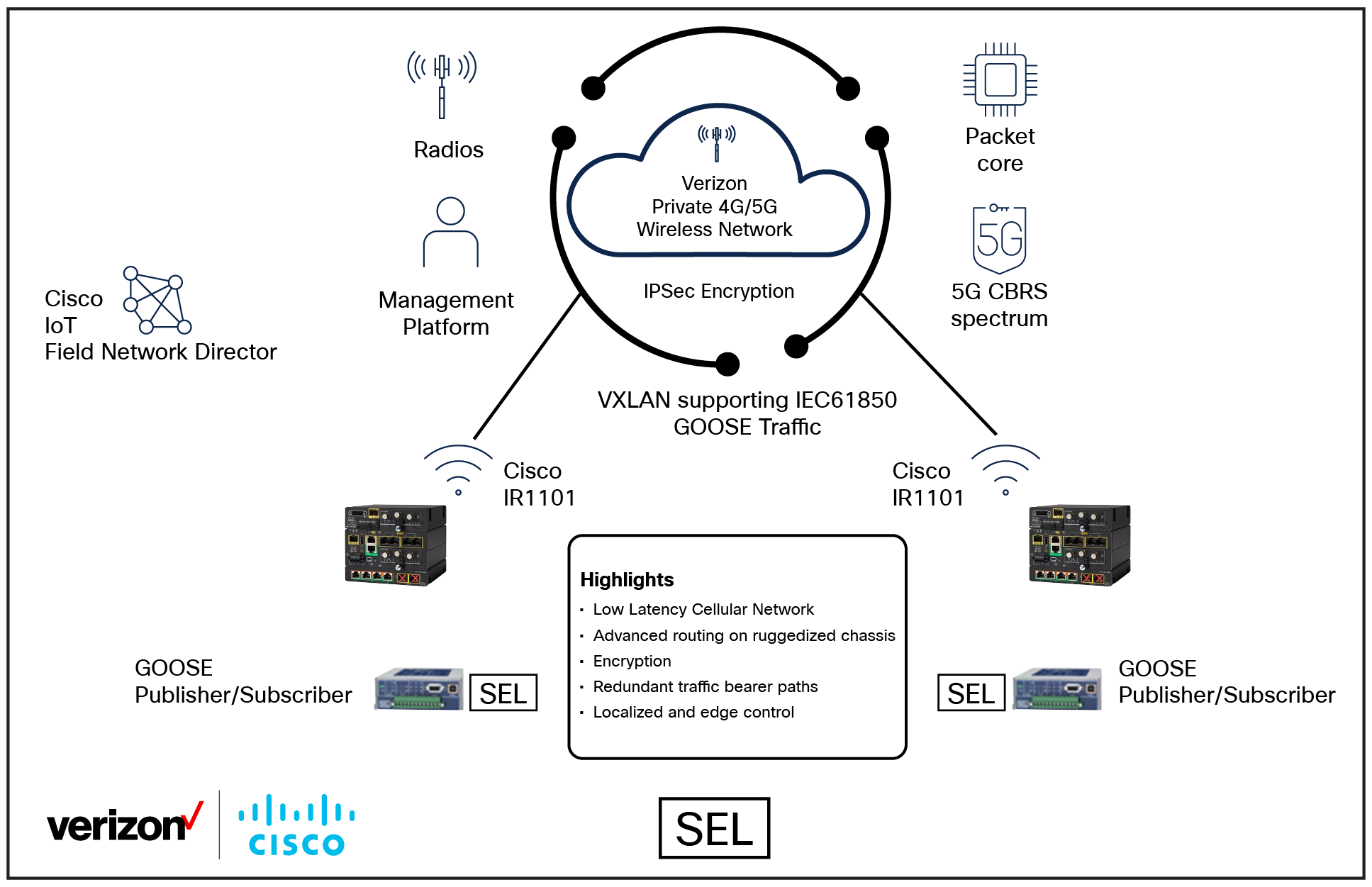
Architecture of the Cisco and Verizon DTT system
Key points for the DTT use case:
● The DER site monitors upstream reclosers for a trip signal.
● The DER site disconnects itself from the grid when it receives the required trip signal.
● The Catalyst IR1101 router with Cisco ® cellular plug-in modules is used to allow flexibility in the selected cellular module required.
● Standards-based VXLAN is used to transport the Layer 2 multicast GOOSE messages.
● IPsec/IKEv2 tunnels are used for security between all endpoints.
● Scalability is required for more complex topologies.
● Security, IPsec for WAN side encryption, and the Catalyst IR1101 router also support MACsec on the LAN ports with SEL-651R reclosers.
Cisco will be releasing an updated validated design for distribution automation that will include the DTT use case over cellular.
Cisco Catalyst IR1101 Rugged Router data sheet
Cisco IoT Field Network Director data sheet

IMAGES
VIDEO
COMMENTS
Direct Transfer Trip Scheme (DTT) (This is technically not a pilot scheme but requires a pilot channel) Direct Transfer Trips (DTT) are initiated from station relays when a serious event occurs in the substation. Some of these events are breaker failure, bus faults, transformer failure, etc. A lockout relay (86 device) is assigned to each event.
We're continuing our end-to-end testing series by looking at the two simplest communication-assisted trip schemes used. Watch this Direct Transfer Trip and ...
Voltage and frequency can vary if the generator does not provide regulation. The supply utility is no longer controlling voltage and frequency. This can potentially cause voltage sags, potentially damaging customer equipment which the utility is responsible for, but has no control over. Traditional Transfer Trip Methods - DTT.
In this video we're going to look at Direct Transfer Trip schemes or DTT schemes and then we're going to look at Direct Under-Reaching Transfer Trip schemes (or DUTTs). This video is part of a series. If you have not watched Understanding Line Distance Protection, the link is on the screen right now, then go watch that video first, so you ...
Underreaching transfer trip schemes include two variations: direct underreach and permissive underreach. The communications for this type of relaying are generally the same as for the overreaching systems, using audio tones with frequency shift keying over microwave, leased line, or fiberoptic communications channels .
customers are seeking alternative solutions for Direct Transfer Trip applications. The three solutions covered here over dedicated dark fiber, T1, and Ethernet connectivity provide customers with the flexibilit. o use what is available to them or reduce costs through leased line replacement. Each of the TC Communications products used in these ...
Scope. DERs are resources connected to the distribution system close to the load, such as DPV, wind, combined heat and power, microgrids, energy storage, microturbines, and diesel generators. Energy efficiency, demand response, and electric vehicles are also sometimes considered DERs.
Underreaching Transfer Trip (DUTT), and Direct Transfer Trip (DTT). Each of these schemes. 3 requires the relay at one line terminal to communicate to the relay at the other line terminal that it either does or does not "see" a fault in the forward or reverse direction. Armed with this remote
uses direct transfer trip protection DTT schemes to take generators offline when there is a fault rather than risk the generator islanding with a Consumers Energy load. They also use permissive overreaching transfer trip (POTT) and current differential for system coordination. They rely on leased
View as PDF. Direct Transfer Trip (DTT) is a teleprotection scheme that involves sending trip signals from one location to another via a telecommunications transport, such as a phone line, radio, or fiber optics. It is commonly used for substations to detect substation faults and create lines of isolation while the faults are under investigation.
a direct transfer trip or intertrip technique, the logic of which is shown in Figure C4.4. A contact operated by the Zone 1 relay element is arranged to send a signal to the remote relay requesting a trip. The scheme may be called a 'direct under-reach transfer tripping scheme', 'transfer trip under-reaching scheme', or 'intertripping
Direct Transfer Trip (DTT) is an application of communication and relay controls intended to disconnect large DERs, including community solar, during grid fault events to prevent ... Historically, transfer trip is implemented whenever a large synchronous machine (like a generator) is connected to a utility feeder. Solar and storage technologies ...
• Direct Transfer Trip (DTT) provides a communications signal from the Area electric power system component such as a feeder breaker or automatic line sectionalizing devices to the DR or the addition of sync-check relaying or undervoltage-permissive relaying at the feeder breaker or automatic line sectionalizing devices. [4]
We're continuing our end-to-end testing series by looking at the two simplest communication-assisted trip schemes used. Watch this Direct Transfer Trip and Direct Under-Reaching Transfer Trip Schemes Video to learn more about these two schemes.
direct transfer trip signals from the delivery point at the transmission substation or from each distribution substation to the DG sites. One solar site was just over 1000 feet from the substation, therefore direct fiber connection could be used. The other communication links required approximately 27 miles of
This is achieved via Direct Transfer Trip (DTT) signals, traditionally sent between substations and remote DG sites using leased telephone lines. Due to the highly specialized and critical nature of DTT systems, the equipment, including the communication infrastructure, must be extremely reliable and conform to highest substation standards. ...
Temporary loss of communication. Provide Anomaly Detection Protection. Provide true redundant communication capability. Provide Event and Fault Reports to operators. All DTT devices aware of all feeder circuit primary switch statuses. Ensure system is interoperable and future proof. IEC61850 Standard.
o Direct transfer trip (DTT). In DTT, the utility's breaker or other isolation device is tied to a transmitter that sends the breaker's status to the DG. o Power line carrier communications (PLCC). PLCC is a form of DTT in which the communications channel is the power line itself. o Integration of inverters into utility SCADA.
The paper will address the security concerns that many Utilities might face. Two new innovations to increase the DG site's availability will be discussed. 1) Automatic Direct Transfer Close. If system conditions return to normal after a DTT event, the system will automatically close the DG site back in onto the feeder.
proposed the use of the modified Direct Transfer Trip (DTT) teleprotection scheme for a closed circuit distribution network, using an OMICRON CMC-356 test box for its validation. Methodologies based on the use of computational platforms are also commonly reported for analysis and evaluation of teleprotection schemes.
For this reason, even something like POTS gets used for direct transfer trip - a high-speed protection scheme. Low latency is one aspect, but bandwidth is another. Specific protective schemes, like line current differential, require high bandwidth to accommodate significant data flow between relays. Both fiber and digital microwave radio can ...
Direct transfer relaying is an example of a grid application where utilities need a dependable and low latency wireless communication solution in order to send a trip signal to a remote or far away location.
One such scheme is Direct Transfer Trip (DTT), where upstream substations need to trip DER assets off the network in the event that the substation feeder breaker opens. Traditionally, DTT signals were sent between substations and remote Distributed Generation (DG) sites using leased telephone lines. DTT systems are installed for critical high ...