Ukraine war latest: Zelenskyy sacks air force chief; girl among six killed in Russian bomb attack that hit Kharkiv playground
Ukrainian President Volodymyr Zelenskiy has dismissed the country's air force commander Mykola Oleshchuk after claims an F-16 pilot was killed by friendly fire. Six people have died, including a 14-year-old girl on a playground, in a Russian guided bomb attack on Kharkiv, officials say.
Friday 30 August 2024 21:50, UK
Please use Chrome browser for a more accessible video player
- Zelenskyy sacks Ukraine's air force commander
- Decision comes after MP claimed F-16 pilot was killed by friendly fire
- Girl among six killed with dozens injured in strike on Kharkiv
- Russia accused of war crimes over guided bomb attack that hit playground
- Women killed in strike on Sumy region that hit baby food packaging factory
- Putin to visit International Criminal Court member Mongolia
- Analysis: Why Putin's arrest in Mongolia is unlikely
- Battlefield situation: Latest frontlines in maps
- Watch: Who are Ukraine's secret resistance?
- Your questions answered: Strategic consequences for Ukraine if Pokrovsk falls
- Reporting by Bhvishya Patel , and earlier by Mark Wyatt
We'll be back with more updates and analysis soon, but before we go, here's a recap of the key developments that took place today:
- Volodymyr Zelenskyy has sacked Ukraine's air force commander, days after a pilot died when an F-16 jet crashed
- Six people have died and at least 55 others hurt following a Russian guided bomb attack on the city of Kharkiv;
- Two women died and 11 people were injured by an attack which struck a factory in Sumy that manufactures packaging for baby food, juices and household products;
- The Kremlin announced that Vladimir Putin plans to visit Mongolia - a member of the International Criminal Court which has an issued an arrest warrant for him;
- The Ukrainian pilot killed when his F-16 fighter jet crashed on Monday was shot down by Ukraine's own anti-aircraft missile system, an MP has claimed;
- Mr Zelenskyy said today's attack on Kharkiv could have been avoided if Ukraine had permission to strike Russian military targets with Western weapons;
- The EU rebuffed a request from Kyiv for the bloc to train Ukrainian soldiers inside the war-torn country.
Ukrainian President Volodymyr Zelenskyy has dismissed the country's air force commander Mykola Oleshchuk.
The sacking was announced on Friday in a presidential decree.
There was no immediate explanation from Mr Zelenskyy for his decision but it comes days after a Ukrainian pilot was killed when his F-16 jet crashed on Monday.
Lieutenant Colonel Oleksiy Mes was killed while defending Ukraine's skies in a Western-donated warplane.
Ukrainian MP Mariana Bezuhla has claimed the jet was shot down by the country's own anti-aircraft missile system.
In response to Ms Bezuhla before his sacking, Lieutenant General Oleshchuk said her comments were a "tool to discredit the top military leadership".
"Mariana, the time will come when you will apologise to the entire army for what you have done, I hope in court!", he added.
Six people are now known to have died following the Russian guided bomb attack on Kharkiv, local authorities have said.
Kharkiv mayor Ihor Terekhov said one child was killed in a playground and three people were killed in a 12-storey apartment block that caught fire as a result of the strike.
The Ukrainian authorities did not give the circumstances in which the two other people died in the strikes, which hit four areas of the city.
As well as those people who died, at least 55 others were injured, officials said.
About 20 of the injured were in severe condition, according to regional governor Oleh Syniehubov.
Top Ukrainian officials have begun a visit to Washington, the Ukrainian presidential office has said.
The delegation includes economy minister Yulia Svyrydenko and defence minister Rustem Umerov.
"We are working in Washington... We are grateful to our partners for their support," the president's chief of staff Andriy Yermak said on Telegram .
The visit comes amid Volodymyr Zelenskyy's renewed a call on Western allies to allow Ukraine to use long-range Western weapons to attack Russian military air bases.
Kyiv says that the most effective way to counter Russian strikes is to target Russian planes, not the bombs themselves.
The US ambassador to Ukraine has called on Russia to be "held accountable for these war crimes" in Kharkiv.
In a statement on X, Bridget A Brink said "Russia struck an apartment building in Kharkiv with a guided aerial bomb, killing several and injuring many, including children".
Kharkiv has been the focus of heavy Russian bombing throughout the war, although there had been a drop in intensity in recent weeks, possibly related to a surprise invasion launched by Ukrainian forces into Russia's Kursk region.
Ukrainian authorities said today's attack involved five aerial guided bombs launched from planes in Russia's Belgorod region, also known as "glide bombs" which are fitted with a navigation system taking them to their targets.
The footage below shows the aftermath of the attack in Kharkiv.
The EU has rebuffed a request from Kyiv for the bloc to train Ukrainian soldiers inside the war-torn country, but will train them as close as possible to Ukrainian territory, EU foreign policy chief Josep Borrell has said.
The EU has trained some 60,000 Ukrainian soldiers inside the economic union's borders since Russia's invasion of the country and will aim to train 15,000 more by the end of the year, Mr Borrell said.
Kyiv has asked the EU to consider some training inside Ukraine, arguing this would be faster, more cost-effective, and logistically easier than inside the EU.
But multiple EU countries are reluctant to deploy troops inside Ukraine, expressing concerns about their safety and questioning whether such a move would divert Ukrainian forces from their core mission, in order to protect trainers.
Mr Borrell told reporters: "Some member states were ready, others reluctant.
"Finally, we decided that the training will be as close as possible to Ukraine, but not in Ukrainian territory."
Ukraine has urged Mongolia to arrest Vladimir Putin on an International Criminal Court (ICC) warrant when he visits next week.
The court issued an arrest warrant in March of last year against Mr Putin, accusing him of the war crime of illegally deporting hundreds of children from Ukraine.
The Kremlin has dismissed the accusation, saying it is politically motivated.
The warrant obliges the court's 124 member states, including Mongolia, to arrest Mr Putin and transfer him to The Hague for trial if he sets foot on their territory.
Now, the Ukrainian foreign ministry has called on the ICC to arrest the Russian leader when he visits Mongolia on 3 September.
"We call on the Mongolian authorities to comply with the mandatory international arrest warrant and transfer Putin to the International Criminal Court in the Hague," the ministry said on Telegram.
Asked earlier today whether Moscow was concerned that Mongolia was a member of the ICC, Kremlin spokesman Dmitry Peskov told reporters: "No, no worries about this. We have a great dialogue with our friends from Mongolia."
Asked whether there had been discussions with Mongolian authorities about the ICC warrant, Mr Peskov added: "Obviously the visit, all of the aspects of the visit have been thoroughly discussed."
Volodymyr Zelenskyy says he held a meeting with the top military commanders of Ukraine this afternoon.
The president said that three key issues were discussed, starting with the situation on the frontlines.
Kursk invasion
Ukraine's top commander says Kyiv's forces have advanced up to 2km in their invasion of Russia's Kursk region.
Oleksandr Syrskyi briefed Mr Zelenskyy via video link and said Ukrainian forces took control of 5sq km of Russian territory.
Discussions were also had over the next set of reinforcements in the area, which Mr Zelenskyy said was "extremely important for strengthening our positions".
General Syrskyi also briefed the president on the ongoing fighting near Pokrovsk, which Ukraine is trying desperately to hold in the face of advancing Russian troops.
Preparing for new academic year
The meeting also covered how Ukraine will deal with the new academic year for schoolchildren, which starts next week.
Mr Zelenskyy heard reports from Prime Minister Denys Shmyhal, internal affairs minister Ihor Klymenko and education and science minister Oksen Lisovyi.
The president said discussions covered security issues, as well as the construction of bomb shelters.
Energy problems
The third key issue addressed was the current state of Ukraine's energy grid following a week of heavy Russian strikes.
Mr Zelenskyy heard analysis of energy issues, including the potential construction of protective structures around key energy infrastructure.
Images are emerging of the aftermath of today's attack on Kharkiv.
Russia denies deliberately targeting civilians, but thousands have been killed and wounded in its strikes during its invasion.
The scenes come as Volodymyr Zelenskyy renews a call on Western allies to allow long-range attacks on Russian military air bases after the attack.
The number of people killed in a Russian strike on Kharkiv has risen to five.
Meanwhile, 40 people have been injured after the Russian missile hit a residential building and playground, according to the regional governor Oleh Syniehubov.
Earlier, we reported that a 14-year-old girl was among the dead.
Be the first to get Breaking News
Install the Sky News app for free

- Actuators and motion control
- Backup power, UPS, surge & IT power distribution
- Clutches and brakes
- Conduit, cable & wire management
- Data & video cables and accessories
- Differentials
- Ducting solutions
- Electrical circuit protection
- Electric vehicles and EV charging
- Electronic components
- Energy storage systems
- Engine solutions
- Filtration solutions
- Fuel systems, emissions and components
- Hose, tubing, fittings and connectors
- Hydraulic motors and generators
- Hydraulic power packs and accumulators
- Industrial controls, drives, automation and sensors
- Life support systems
- Lighting and controls
- Low-voltage power distribution & control systems
- Medium-voltage power distribution & control systems
- Process safety, automation, test and measurement
- Residential
- Safety, security & emergency communications
- Server racks, enclosures & thermal management
- Support systems
- Transmissions
- Utility & grid solutions
- Wiring devices & connectivity
- Brightlayer Experience Hub
- Brightlayer intelligent power management
- Explore our digital catalog
- For developers
- Understanding Industry 4.0
- Data centers
- Eaton Experience Centers
- Food and beverage
- Government and military
- Machine building
- Mining, metals and minerals
- Oil and gas

- News & insights
- Investor relations
- Research & development
- Corporate governance
- Sustainability
- Inclusion & diversity
- Ethics & compliance
- Partnering with Eaton
- Selling to Eaton
- Shunt trip safety switches
Eaton's shunt trip safety switches, a market exclusive, provide remote switching and visible means of disconnect for commercial and industrial applications. In addition, the shunt trip technology enhances safety by providing a means to open a safety switch electronically. This product line provides additional code compliant solutions with optional protection schemes including arc energy reduction (NEC 240.67) and ground fault (including 480 VAC and 1200 A service entrance applications).
- Locate a distributor
- Contact us for custom products

Photo is representative

Core features
- Standard heavy-duty safety switch design with integrated shunt trip module
- Integral arc energy reduction system available (NEC 240.67)
- Integral ground fault protection available for 480 VAC service entrance applications (NEC 230.95)
- Works with emergency stop pushbuttons and other remote signaling means to quickly disconnect power from equipment
- Provides a safety switch solution for oil and gas, industrial plants, utilities, commercial construction and water and wastewater treatment applications
- Includes two-, three- and four-pole configurations for maximum system voltages of 600 VAC with fusible and non-fusible protection options
- Meets Underwriters Laboratories (UL) standards and is listed to the UL98 standard
- Provides a variety of coil voltages, visible means of disconnect, and a standard heavy duty safety switch with integrated shunt trip module
- Passes Class 1 ground fault testing (1200% opening)
View design guide (layouts, technical data and application information)
Download guide spec (26 28 16 13), learn more about power system design basics, switches portfolio.

Advancing personnel and equipment protection with safety switches
Customization available through our flex center, related products.
Safety switches | Electrical Disconnects | Knife Blade | EXO | Eaton
Heavy duty safety switches
Safety switch | General Duty Disconnect | Knife switch | Eaton
General duty safety switches
- Alpha: A to Z
- Alpha: Z to A
STS265UD35CL
- Specifications
Maximum reached
Four is the maximum number of items in the comparison tool.
Two items are required
A minimum of two items are required to use the comparison tool.
Something went wrong
Sorry, we can't get that information right now.
- Remote operation. Code compliance. Unmatched protection Download This document describes the features and benefits of the shunt trip safety switch (PDF 163 KB , 10/01/2021)
- Switching device family line card Download This document contains an overview of the switching device product offering (PDF 730 KB , 04/01/2021)
- Switching devices catalog vol02, tab01 Download Volume 2, Tab 1 - This catalog contains product details and cross-reference for switching devices. (PDF 9 MB , 06/10/2024)
Design guides
- Safety switches design guide Download This design guide provides dimensions, layout examples, technical specifications and application information for low-voltage safety switches. The information in this document supersedes section 28 of the Consulting Application Guide (CAG). (PDF 2 MB , 05/25/2023)
- FAQ Arc energy reduction relay switching devices Download This document reviews frequently asked questions about arc energy reduction relay switches. (PDF 90 KB , 07/01/2020)
Infographics and listicles
- NEC and UL compliant barriers Download This documents explains the NEC and UL compliant barriers (PDF 180 KB , 07/13/2023)
- Switching devices flex center infographic Download This document highlights the capabilities of Eaton’s Flex Center which provides custom solutions for safety switches, enclosed circuit breakers and rotary disconnects. (PDF 141 KB , 10/01/2015)
- Why arc flash protection matters for electrical safety switches Download This infographic reviews the various ways that safety switches can assit with arc flash prevention (PDF 191 KB , 07/01/2020)
Manuals and user guides
- Safety switch renewal parts Download This renewal parts guide reviews Eaton's general duty and heavy-duty safety switch renewal part availability. (PDF 466 KB , 01/30/2024)
Technical data sheets
- Arc energy reduction relay switching devices product platforms Download This document contains technical details for arc energy reduction relay switching devices product platforms. (PDF 1 MB , 04/17/2024)
- Eaton’s heavy duty safety switches with shunt trip capability technical data Download This document contains technical data for Eaton’s heavy duty safety switches with shunt trip capability—remote switching and visible means of disconnect for commercial and industrial applications. (PDF 241 KB , 10/01/2021)
- Fine stranded wire guidelines for safety switches Download This instruction leaflet is presented to guide the installer when utilizing Eaton switches with fine stranded wire. (PDF 202 KB , 02/01/2013)
- Safety Switch Fine Strand Wire Guidelines Download Fine stranded wire guidelines for use with Eaton's General Duty, Heavy Duty, Double Throw and Elevator Control switches (PDF 271 KB , 07/11/2022)
- United States
- Switches and disconnects
- Inclusion and Diversity
- News and insights
- Slavery and human trafficking statement
- Policies and statements
- Terms and conditions
- Responsible sourcing of conflict minerals
- Subscribe to emails
Let's talk big ideas
- Privacy, cookies & data protection policy
- Do not sell my data request (CCPA and other states)
.cls-1 { fill: #b01; } Mitey Titan Industries Inc. (Logo) Mitey Titan Industries Inc.
Search form for mitey titan industries inc., auto trip (rpm switch).
")
$ 295.00
Activated by the pre-set limit. Once the engine goes past this RPM, the switch activates the PASV.
Kit System : Wire Harness; Magnetic Pick-Up; Toggle Switch; RPM Switch
Common Issues with Transfer Switches and How to Fix Them

The whole point of a transfer switch is to make the process of switching your facility over to backup power automatic . That’s why it is incredibly frustrating when you have transfer switch issues . You’re dealing both with the loss of power from the grid and the failure of your backup system to take over or at least take over within a few seconds.
What has caused your transfer switch to fail? And how can you fix it? In general, this is a problem for the professionals . Repairs should always be handled by a certified, licensed and experienced electrician , or you risk harm to not just the person trying the repairs but also everyone in the building and, less significantly but still importantly, damage to your equipment.
While you shouldn’t attempt your repairs, it is still useful to know the common issues and how the professionals will fix them. It's empowering to better understand your equipment and have the terminology and understanding to ask your electrician your questions. So, here are common issues with your transfer switches and how to fix them.
1. Tripped Breaker
Power surges and overcurrents can trip the breaker which serves your transfer switch. When this breaker is tripped, your transfer switch cannot function properly. You should have your electrician check the breaker during the routine maintenance of the system.
2. Corrosion from Moisture, Leaks
Corrosion and shorts are commonly caused by exposure to moisture. Leaks, flooding, or just environmental moisture can damage your transfer switch and the wiring that serves it. You should check to ensure the transfer switch has proper environmental protections. After leaks or natural disasters, your entire electrical system should be checked, including the transfer switch.
You should not approach any wet electrical equipment. Allow electricians to do this, as they know the proper safety protocol that needs to be followed in order for them to stay safe.
3. Loose Connections from Dirt, Debris
Dirt and debris may also get into the transfer switch or interfere with its connections if the switch and the area, in general, are not well-maintained or not properly protected. Loose connections can cause the transfer switch to fail. So, your electrician should clean the area out and then test the contacts. When necessary, he or she will tighten the contacts to ensure they carry current.
4. Damage to the Controller
Controllers are an essential and sensitive component of a transfer switch which may fail over time or become damaged. You may need to repair or replace the controller.
5. ATS Issues
If the transfer switch turned your backup generator back on but didn’t turn it back off, even after its normal cool-off period should have ended, the most likely problem is an issue with the ATS. This tells the transfer switch to turn back to utility power and shut down the backup generator.
The ATS has had its own loose connections, or it may have been grounded somehow. In either case, an electrician can fix this problem.
6. Overheating
If your transfer switch was exposed to very high heat conditions, or it cycled too fast and created a great deal of heat itself, then it may burn out the solenoids or cause other serious heat damage. In this case, the transfer switch may stop working altogether. This issue usually requires replacement.
7. Improper Installation
If the transfer switch was installed recently and did not have the time to be tested before it was required, it is possible that the switch or some component of it was never installed properly in the first place. This is rare, but it does happen.
Also, another rare issue may be that the transfer switch has a manufacturer’s defect that prevents its use. In this case, your electrician should be able to diagnose the issue for you and advise you as to warranty issues or speaking with the manufacturer about the problem.
How Can You Avoid Transfer Switch Problems?
There are many other potential issues that your transfer switch may develop, and repair and replacement may be expensive.
Regular maintenance of your electrical system and regular testing of your backup supply, including your transfer switch, can ensure that it all operates properly and that you will have backup power when you need it.
Contact us for all of your electrical generator system and transfer switch service, maintenance and testing needs.
Recent Posts
- Why Are Static Transfer Switches Gaining Popularity?
- Common Defects Associated With Residential Generators
- How to Choose Parts for Your Mobile Generator in Ventura County
- Important Tips To Prepare Your Generator For Thunderstorms
- Best Diesel Generator Installation Service In Ventura County
- Automatic Transfer Switches
- Diesel Generators
- Gaseous Generators
- Generator Service
- Industrial Engine Service
- Mobile Power Generators
- Paralleling Controls & Switchgear
- Parts & Accessories
- Residential Generators
- Marine Diesel Power
- February 2024
- January 2024
- December 2023
- November 2023
- October 2023
- September 2023
- August 2023
- February 2023
- January 2023
- December 2022
- November 2022
- October 2022
- September 2022
- August 2022
Leading Manufacturer of Safety Interlock Switches and Machine Guard Safety Switch Devices for Automation and Process Safety
Full Name Position Organisation Email Telephone Message
The file should download on submission. Make sure that you have popups enabled.
Product Name First Name Position Organisation Email Telephone Address
Full Name Position Organisation Email Telephone Address Product or part number required
220826_EDS-UGB-NET-CS_V1-00
Ugb-net-exp-ps gsdml file v2.34.
Full Name Position Organisation Email Telephone Address Product or part number of CAD required
[wpforms id=”242790″]
First Name (required)
Surname (required)
Position (required)
Organisation (required)
Your Email (required)
By clicking send, you are agreeing for your details to be shared with IDEM’s commercial team. Your details will not be shared with any third-party organization.

GLS-AR: Grab Wire Rope Pull Auto Reset Trip Safety Switch

ROPE PULL OPERATED. AUTO-RESET STOP SWITCH.
Grab Wire Auto-Reset Stop Rope Switches are mounted on machines and sections of plant conveyors to initiate a momentary control signal command from any point along the installed rope length.
Designed and manufactured in the United Kingdom the GLS-AR is offered with either a die-cast painted yellow or stainless steel 316 housing and is extremely robust for virtually all applications.
Pulling the rope causes instant tripping of the control circuit contacts.
Ideal for normal stop circuits where manual resetting of the switch is not required. This switch is not an emergency stop, it is a “trip” switch with automatic reset.
The switches have a positive mechanical linkage between the switch contacts and wire rope as per IEC60947-5-1. The switches are brought into the operational condition by pre-tensioning the rope by use of a tensioner device which clamps the rope and then hooks to the switch eyebolts. Correct tension can be observed by viewing the tension indicator on the switch housing. Once tensioned the switch contact blocks are set to the operational condition, i.e. Signal contacts Closed – Auxiliary contacts Open.
All of the switches have wire breakage monitoring. On pulling or breakage (tension loss) of the rope, the normally closed Signal contacts are Opened and the Auxiliary contacts are Closed. The switches will be returned to the operational condition as soon as the rope returns to the set position.
FOR PRODUCT DATA SHEET, CATALOGUE PAGE FOR FURTHER INFORMATION AND SALES/PART NUMBER OR TO REQUEST CAD DRAWING PLEASE CLICK ON THE RELEVANT DOWNLOAD BUTTON.
Product Specifications
You may also like....

Rope Kit / Rope Only

Stainless Steel Safety Spring
- Electronics
- Power Accessories
Add to your order

- No Additional Cost: You pay nothing for repairs – parts, labor, and shipping included.
- Coverage: Plan starts on the date of purchase. Malfunctions covered after the manufacturer's warranty. Power surges covered from day one. Real experts are available 24/7 to help with set-up, connectivity issues, troubleshooting and much more.
- Easy Claims Process: File a claim anytime online or by phone. Most claims approved within minutes. If we can’t repair it, we’ll send you an Amazon e-gift card for the purchase price of your covered product or replace it.
- Product Eligibility: Plan must be purchased with a product or within 30 days of the product purchase. Pre-existing conditions are not covered.
- Terms & Details: More information about this protection plan is available within the “Product guides and documents” section. Simply click “User Guide” for more info. Terms & Conditions will be available in Your Orders on Amazon. Asurion will also email your plan confirmation with Terms & Conditions to the address associated with your Amazon account within 24 hours of purchase.
- Buy a lot of stuff on Amazon? Tons of items eligible for coverage, from the latest tech like Laptops, Game Consoles, TVs, Phones, and Cameras to major appliances, sporting goods, tools, toys, personal care, furniture, and more.
- Accidents Happen. That’s why for your portable products we cover accidental damage from handling such as drops, spills and cracked screens. We also cover electrical and mechanical malfunctions, power surges, and wear and tear.
- Past and Future Purchases covered. 30 days after you are enrolled, all eligible past purchases (up to 1 year prior to enrollment) and future eligible purchases made on Amazon will be covered by your plan as long as you are enrolled.
- Fast, easy claims. Frustration-Free claims, with most filed in minutes. We will fix it, replace it, or reimburse you with an Amazon e-gift card for the purchase price of your product (excluding tax). File at Asurion.com/amazon.
- No Hidden Fees. For just $16.99 a month + tax you’re covered for up to $5,000 in claims per 12-month period. *THIS PROGRAM IS MONTH-TO-MONTH AND WILL CONTINUE UNTIL CANCELED* Coverage for all products ends 30 days after the plan is canceled. Cancel any time.
Buy new: #buybox .a-accordion .a-accordion-active .a-price[data-a-size=l].reinventPriceAccordionT2 .a-price-whole { font-size: 28px !important; } #buybox .a-accordion .a-accordion-active .a-price[data-a-size=l].reinventPriceAccordionT2 .a-price-fraction, #buybox .a-accordion .a-accordion-active .a-price[data-a-size=l].reinventPriceAccordionT2 .a-price-symbol { top: -0.75em; font-size: 13px; } $458.00 $ 458 . 00 FREE delivery Friday, September 6 Ships from: BeachAudio Sold by: BeachAudio
2 year electronics protection plan, 3 year electronics protection plan, asurion complete protect: one plan covers all eligible past and future purchases on amazon, save with used - like new #buybox .a-accordion .a-accordion-active .a-price[data-a-size=l].reinventpriceaccordiont2 .a-price-whole { font-size: 28px important; } #buybox .a-accordion .a-accordion-active .a-price[data-a-size=l].reinventpriceaccordiont2 .a-price-fraction, #buybox .a-accordion .a-accordion-active .a-price[data-a-size=l].reinventpriceaccordiont2 .a-price-symbol { top: -0.75em; font-size: 13px; } $399.99 $ 399 . 99 free delivery friday, september 6 ships from: cloud crest it sold by: cloud crest it.

Image Unavailable

- To view this video download Flash Player
Tripp Lite Metered PDU, Auto-Transfer Switch (ATS), 20A, 120V, 1.92kW, Single-Phase - 16 Outlets (5-15/20R), Dual 12ft L5-20P Input Cords - 1U Rackmount, TAA Compliant, 2 Year Warranty (PDUMH20ATS)
Purchase options and add-ons, about this item.
- SINGLE-PHASE ATS PDU DISTRIBUTES AND MONITORS POWER: ATS PDU allows real-time local current metering to prevent circuit overloads and enables redundant power for non-redundant network devices. Features eight NEMA 5-15R 120V outlets distribute AC power to connected equipment. Ideal for network IT & rack applications.
- SWITCH FROM PRIMARY TO SECONDARY POWER SOURCE IN MILLISECONDS: Automatic transfer switching (ATS) switches to the secondary source within 2–7 milliseconds if the primary source becomes unstable. ATS processor constantly evaluates the power quality of both input sources.
- DIGITAL LOAD METER: Reports the total load for all connected equipment. Ensure load levels remain below maximum capacity to avoid costly downtime or damaged equipment.
- TAA-COMPLIANT FOR GOVERNMENT PURCHASES: Compliant with the Federal Trade Agreements Act (TAA), which makes it eligible for GSA (General Services Administration) Schedule and other federal procurement contracts.
- RELIABLE PRODUCT FULLY BACKED AND SUPPORTED: This product is covered by a 2-Year Limited Warranty and is supported by Tripp Lite's Chicago-based expert technical support team over phone and email.
Buy it with

Similar items that may ship from close to you

Top Brand: Tripp Lite
Compare with similar items, product description.
SINGLE-PHASE 20A ATS PDU DISTRIBUTES AND MONITORS NETWORK-GRADE POWER IN REAL TIME: This metered PDU provides real-time local reporting of the total load level via its built-in digital current metering. Ideal for network IT applications, small computer rooms and other equipment rack applications, the PDUMH20ATS features 16 NEMA 5-15/20R 120V outlets for connecting equipment. Dual 12-foot (3.7-meter) power cords with NEMA L5-20P inputs (two 5-20P adapters are included) connect to separate primary and secondary mains circuits, backup generators, UPS systems or utility power grids, including out-of-phase sources. SWITCHES FROM PRIMARY TO SECONDARY POWER SOURCE IN MILLISECONDS: Automatic transfer switching (ATS) allows the PDU to switch to the secondary source within 2-7 milliseconds, should the primary source fail or become unstable, to ensure your connected equipment operates without interruption. An on-board ATS processor constantly evaluates the power quality of both input sources. It prevents switching if the secondary source is unavailable or of lower quality than the primary source. DIGITAL LOAD METER HELPS PREVENT POTENTIALLY EXPENSIVE OVERLOADS: A digital ammeter reports the total load for all connected equipment. Monitoring amperage helps ensure load levels remain well below maximum capacity with no danger of overload that could lead to costly downtime or damaged equipment. Maintaining proper load levels, even while adding new equipment, can keep your TCO (total cost of ownership) low. MOUNTS INTO 1U OF RACK SPACE OR ON A WALL: Use the included mounting hardware to install the all-metal housing into 1U of space in an EIA-standard 19-inch rack. You may also use the mounting brackets to secure the PDU to a wall or under a counter. TAA-COMPLIANT FOR GSA SCHEDULE PURCHASES: The PDUMH20ATS is compliant with the Federal Trade Agreements Act (TAA), which makes it eligible for GSA (General Services Administration) Schedule and other federal procurement contracts.
Product information
Warranty & support, looking for specific info, videos for this product.

Click to play video

How to Choose a PDU: Metered PDUs by Tripp Lite by Eaton
TRIPP LITE. BY EATON
Customer reviews
- 5 star 4 star 3 star 2 star 1 star 5 star 0% 0% 0% 0% 0% 0%
- 5 star 4 star 3 star 2 star 1 star 4 star 0% 0% 0% 0% 0% 0%
- 5 star 4 star 3 star 2 star 1 star 3 star 0% 0% 0% 0% 0% 0%
- 5 star 4 star 3 star 2 star 1 star 2 star 0% 0% 0% 0% 0% 0%
- 5 star 4 star 3 star 2 star 1 star 1 star 0% 0% 0% 0% 0% 0%
Customer Reviews, including Product Star Ratings help customers to learn more about the product and decide whether it is the right product for them.
To calculate the overall star rating and percentage breakdown by star, we don’t use a simple average. Instead, our system considers things like how recent a review is and if the reviewer bought the item on Amazon. It also analyzed reviews to verify trustworthiness.
No customer reviews
- Amazon Newsletter
- About Amazon
- Accessibility
- Sustainability
- Press Center
- Investor Relations
- Amazon Devices
- Amazon Science
- Sell on Amazon
- Sell apps on Amazon
- Supply to Amazon
- Protect & Build Your Brand
- Become an Affiliate
- Become a Delivery Driver
- Start a Package Delivery Business
- Advertise Your Products
- Self-Publish with Us
- Become an Amazon Hub Partner
- › See More Ways to Make Money
- Amazon Visa
- Amazon Store Card
- Amazon Secured Card
- Amazon Business Card
- Shop with Points
- Credit Card Marketplace
- Reload Your Balance
- Amazon Currency Converter
- Your Account
- Your Orders
- Shipping Rates & Policies
- Amazon Prime
- Returns & Replacements
- Manage Your Content and Devices
- Recalls and Product Safety Alerts
- Registry & Gift List
- Conditions of Use
- Privacy Notice
- Consumer Health Data Privacy Disclosure
- Your Ads Privacy Choices
- Check Stock
- Sales Portal
Thermal Overcurrent Circuit Breakers
Typical applications.
Thermal circuit breakers (circuit protectors, resettable fuses, circuit breakers for equipment protection) are ideally suited to overload protection of motors, transformers, magnetic valves, on-board electrical systems and low voltage lines.
The trip time of thermal circuit breakers depends on the height and of the duration of the overload current and the ambient temperature. With higher current ratings, the bimetal or hot wire is heated up until the defined trip time is reached and the device ensures genuine physical isolation of the contacts.

Thermal circuit breaker, integral type, single pole

Thermal circuit breaker for pcb mounting, single pole

Thermal circuit breaker for snap-in mounting, single pole

Thermal circuit breaker for threadneck panel mounting, single pole

Thermal circuit breaker with manual release button, plug-in or snap in panel mounting

129-L11-H-KF
Thermal automotive circuit breaker with manual release, for base mounting

Push-push thermal switch/circuit breaker combination, single pole

Single pole thermal circuit breaker, integral type

Thermal circuit breaker for snap-in panel mounting, single pole

Thermal circuit breaker for threadneck panel mounting, double pole, one pole thermally protected

Thermal automotive circuit breaker with automatic reset function
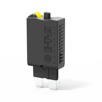
Miniaturised thermal automotive circuit breaker with colour-coded manual release

Thermal circuit breaker, plug-in type, single pole, switching function optional

Thermal circuit breaker for snap-in panel mounting, rocker operated, fast acting

Miniaturised thermal circuit breaker for pcb mounting, fast acting

Miniaturised thermal circuit breaker for threadneck panel mounting, fast acting

Automotive thermal circuit breaker, colour-coded housing, standard fuseblock mounting

Automotive thermal circuit breaker with manual release option

Automotive thermal circuit breaker with automatic reset function

Single pole, thermal miniaturised circuit breaker designed for automotive applications

Single pole thermal reset circuit breaker in a miniaturised design intended for threadneck or snap-in mounting, dimensions: 32.0 x 27.0 x 13.6 mm.

3120-N, thermal circuit breaker, snap-in mounting, 1-pole, 2-pole

Thermal circuit breaker with rocker actuation, single, double or three pole

Thermal circuit breaker with rocker actuation, single pole, water splash protected (IP66)

Single pole three-position switch, water splash protected (IP66)

Thermal circuit breaker with push buttons, three pole

Thermal circuit breaker for threadneck panel mounting

Thermal circuit breaker for flange mounting and manual release option

Thermal circuit breaker with threadneck, push-push actuation

Thermal circuit breaker for threadneck panel mounting, with auxiliary contacts

Single pole bimetal operated motor protection control, surface mounting, autoreset
Interactive Virtual Sample Kit
E-T-A's new interactive sample case features circuit breakers, relays, and power distribution modules. With the click of your mouse you can:
- Spin products with 360° CAD product viewer
- Filter products by attributes
- View product datasheets
- Add samples to a bag to request physical samples
Build your custom sample kit today
Fuse vs. circuit breaker: How to choose the right device for your application
Is a fuse or circuit breaker best for your design? Here are some pointers to help you decide. Three main factors go into choosing between circuit breakers and fuses: Convenience for the user, cost, and degree of protection. This white paper will give you guidance on what circuit protection device is best for your equipment.
Read White Paper
12 Most Common Mistakes When Specifying Circuit Protection for Equipment
It's only a circuit breaker. Yet there is enough complexity and confusion when it comes to specifying circuit protection that many engineers are designing equipment with too little or too much protection. Under protected circuits leave equipment vulnerable to damaging electrical surges. Over protected circuits add cost and can lead to nuisance tripping. Like Goldilocks and the three bears, the goal is to specify circuit protection that is "just right".
- International
First Responder/MIL/Veteran Discount
All orders will be shipping in 1-7 business days

PMM RATTLER/VIRTUS/MPX/SPEAR LT Full-Auto Kit
$ 130.00
Product Details
Product Details:
- 1 x Full-auto trip bar, machined in house from 1018 steel and salt-bath nitride coated, which provides exceptional corrosion resistance and durability.
- 2x RATTLER/VIRTUS/MPX trip bar retaining spring pins. (Will need to be ground/machined to length)
- 1x RATTLER/VIRTUS/MPX full auto sear pin (Lower need to be machined to fit sear as well as sear retaining pin)
All applicable federal and state laws must be followed.
THIS PRODUCT CANNOT BE SHIPPED TO CALIFORNIA, COLORADO, DC, ILLINOIS, NEW JERSEY, NEW YORK, PUERTO RICO, OR WASHINGTON. ORDERS WILL BE CANCELLED LESS A 6% CANCELLATION FEE
!!!!PMM WILL NOT INCLUDE INSTRUCTIONSOR ANSWER QUESTIONS ABOUT INSTALLATION OR MACHINING ANY SELECT FIRE COMPONENTS!!!!
Additional information
Best sellers:.
Products we support
- PMM X-COMP Builds
- First Responders/MIL/Veteran Discount
- PMM Shooting Drills
- Machine Work Lead Times
- International Customers
- Terms & Conditions
Join Our Mailing List
Parker mountain machine © 2024. all rights reserved..
Welcome to the ASCO Website
Basic Automatic Transfer Switch Functions
Get the latest white papers, product news and insights straight to your inbox.
What is the purpose of a Trip Switch?
Understanding the trip switch: a guide to electrical safety.
The trip switch, often referred to as a circuit breaker or residual-current device (RCD), plays a crucial role in safeguarding our homes and businesses from electrical hazards. This essential component monitors the flow of electricity within a circuit and automatically cuts off power when it detects a fault, such as an overload or a short circuit. In this blog post, we’ll delve into the importance of trip switches, how they work, and why they are a fundamental aspect of electrical safety.
What is a Trip Switch?
A trip switch is a safety device designed to protect electrical circuits from overloads, faults, and other electrical issues that could pose a risk to property and personal safety. When an abnormal electrical condition is detected, such as a surge in current or a ground fault, the trip switch immediately interrupts the circuit to prevent potential damage to appliances, wiring, and the risk of fire or electric shock.
How Does a Trip Switch Work?
The basic principle behind a trip switch is simple yet effective. It continuously monitors the electrical current flowing through a circuit. If the current exceeds a predetermined threshold or deviates from its normal path, indicating a fault, the trip switch quickly triggers a mechanism to cut off the power supply. This rapid response helps to minimize the risk of electrical fires, equipment damage, and personal injury.
Why is a Trip Switch Important?
Ensuring the proper functioning and maintenance of trip switches is crucial for electrical safety in both residential and commercial settings. A malfunctioning or outdated trip switch can fail to respond to electrical faults, leaving your property vulnerable to potential hazards. Regular inspections, testing, and timely replacement of trip switches are essential to ensure they are functioning correctly and providing reliable protection against electrical faults.
In conclusion, the trip switch is a vital component of modern electrical systems, serving as a first line of defense against electrical hazards. By continuously monitoring and interrupting abnormal electrical conditions, trip switches play a pivotal role in safeguarding our homes, businesses, and loved ones. Regular maintenance and proactive monitoring of trip switches are key to ensuring their effectiveness and maintaining a safe and secure electrical environment. If you have concerns about your trip switch or need professional assistance with electrical safety measures, don’t hesitate to contact MR AMP. Our team of experienced electricians is here to help you with all your electrical needs and ensure the safety and reliability of your electrical systems.
- Plan a Road Trip
- Plan a Flight
- Find an Airport
- Where to Stay
- All Questions
Road trip planner
Starting City
Destination City
Or switch to flying
Planning a road trip?
Get advice from people who have done the same trip.
The Trippy road trip planner automatically calculates the optimal itinerary including stops recommended by Trippy members, favorite restaurants and hotels, local attractions and things to do based on what people who live in the area have suggested, and more.
Once you have a quick trip planned, you can customize every detail, adding or removing stops, or changing what time you leave in the morning or how long you stay at each stop. Then you can save your custom trip and share it with friends and family.
Let us know if you have requests for more features you'd like to see in the trip planner!
Solutions for the thermal management of electrical enclosures and industrial processes in different fields

Windows & door solutions for sun and insects’ protection, included speed reducers, spring adjustment devices and accessories
Two Business Units, a single vision
- door limit switches
Operating on non-live electrical panels
The limit switches have the main function of interrupting the current in the electrical panel when it is opened. To ensure maximum safety during operations on panel components.
NEWS / BRAND / TOOL

Search for our products
- enclosure components
The products of the series: door limit switches
Safety door limit switches.

Multiple applications
The limit switches are applied on the frame of the electrical panel and can turn on the lights, turn off a fan or a heater or cut off the power supply in general when the door is opened or closed.

Available models
The limit switches are available with different actuating heads and contact blocks to meet all installation requirements.

Interoperability
The limit switches are also used in conjunction with the flashing signal device and the Sensis device to detect the opening/closing of the electrical panel door.

Safety and convenience
Limit switches are a practical solution for safety sensing applications in switch cabinets.

Mechanical activation
The limit switches are activated mechanically and can interact with another device, or interrupt the electrical connection of the electrical panel.

News / Events
Here you can find updates and news regarding events, trade shows, webinars and all the appointments we will attend. In addition, we will announce the launch of new products and provide exclusive news for community members

New digital catalogue
The new version of product catalogue offers extra digital content: by browsing it online, you can reach a greater level of detail. Just a click on the code to directly access the single data sheets for a technical insight.

New roof exhaust unit TP series in CC
Fandis has developed a new energy-saving roof ventilation solution, expanding the range of plastic towers with 24 and 48V DC powered models. Visit the dedicated section for more information

Safety Critical Drive-by-Wire
Control systems for autonomous vehicle fleets
Introducing Sygnal DBW
Control accelerator, brake, and steering with the first by-wire control system designed for deployment

Safety-Critical
Sygnal DBW was engineered from first principles to meet demanding requirements for use in safety-critical systems
Solid-State
Proprietary solid-state circuitry performs all signal muxing without the use of relays.
Automotive-Grade
Harnesses built to OEM standards, housing rated for IP67+, automotive-grade electronics, and traceability records maintained for 10 years.
Along with the lowest price-point in the industry, Sygnal DBW can be moved between vehicles as they are retired, protecting your investment and paying dividends for years to come.
Empower your safety driver
Sygnal DBW automatically releases control when it detects interactions with vehicle controls from the safety driver. In the event of an emergency, the E-Stop button reverts the system to a fail-safe state.

On the road to ASIL-D
Sygnal DBW was designed to be used in ASIL-D safety concepts. Sygnal is working toward SEooC certification in 2025. Dual redundant microcontrollers, power, CAN communications, and signal circuitry are provided. Extensive system diagnostics are available with fault behavior configurable in software.

Put down the wire cutters
And back away slowly... Every Sygnal DBW is designed for quick and easy integration with supported vehicles. Simply unplug the OEM sensor connectors in the driver's footwell and plug in the DBW harness. The MCM module is small enough to easily tuck under the dash for a seamless installation. The emergency stop button is located in a cupholder for simple installation and within easy reach of the safety driver.

For Engineers, By Engineers
As engineers, we know that one of the most valuable parts of a product isn't the product at all; it's the documentation. The Sygnal DBW knowledge-base is our first-line of support, constantly refined to give engineers any answer they need as soon as they need it.

Vehicles that can go the distance
Sygnal supports vehicles that are ideal for fleets: low cost, high reliability, great retained value, and global availability

Our flagship vehicle is the 2017+ Kia Niro. Sygnal DBW works with all models and trims, including hybrid, plug-in hybrid, and EV. This workhorse AV platform has ample interior volume for equipment, a comfortable passenger cabin, and extremely low operating costs.

Kia Soul EV is a smaller vehicle with ample trunk volume for equipment. Used versions can be sourced for less than $10K USD, making the Soul EV an economical option for fleets or early AV technology development.

Sygnal DBW was designed for maximum versatility. While we're focused on adding features to existing supported vehicle platforms, we're happy to consider custom vehicle requests. Our technology can be easily adapted for both retrofit and OEM applications. Don't hesitate to contact us to discuss your vehicle requirements and we'll do our best to find a solution,
What's in the Box?
Everything you need to take control

The heart of the system, the MCM contains dual ASIL-B microcontrollers, dual-redundant power and communication, and our proprietary solid-state signal muxing circuitry. Even with all that, it's still small enough to fit up under the dash with room to spare.
Master Control Module (MCM)
Emergency stop module, vehicle-specific harness, usb controller.
With a twist-lock emergency stop button and LED condition indicators, the cleverly designed Emergency Stop Module mounts easily in any cupholder. The housing can be easily reconfigured to allow the cable to exit in any direction for the cleanest integration.
Every Sygnal system includes a modular, multi-part wiring harness built to OEM standards. These harnesses can easily be swapped or upgraded for special applications. OEM connectors are provided for easy integration with no wire cutting.
Use the included USB gamepad after first installing the system to test and confirm proper operation by controlling the vehicle. Also works well to amaze your friends who have no idea what you do.
Frequently Asked Questions
Not seeing your question here?
Sygnal DBW generates analog signals that behave identically to the vehicle sensors used to detect human input, such as pushing the brake pedal, throttle pedal, or moving the steering wheel. During the initial setup, Sygnal DBW actually learns the unique signal characteristics of your vehicle. This means that the OEM safety concept remains relatively intact compared to other techniques such as CAN bus spoofing. It's also minimally invasive and requires no permanent modifications to the vehicle.
Sygnal DBW ships with a vehicle-specific wiring harness that interfaces with all OEM systems without any modification. Simply unplug the factory connectors and plug the MCM harness in. Depending on the level of integration, you may opt to modify interior or exterior panels, but it's not necessary in any of the Sygnal DBW kits.
This is a question for your engineering department. If you're operating automated vehicles in uncontrolled environments, it's critical to analyze the entire system for unacceptable risk and mitigate any potential failures accordingly. Sygnal DBW is designed to facilitate many different system safety concepts, so please let us know if you have questions regarding your particular system.
The Sygnal user agreement doesn't limit where Sygnal DBW is used, HOWEVER (and this is a big however), it's up to the vehicle integrator to implement an appropriate vehicle safety concept. Sygnal DBW is built with lots of useful functionality to implement your safety concept, but it's completely unable to assure anything unless it's being used "in context". If any of this sounds confusing to you, we suggest you begin your safety journey with a training in ISO 26262 by an accredited firm such as KVA . For the safety of yourself and others, we recommend you don't operate on public roads until you have a safety concept designed, implemented, tested, and documented.
You'll need a CAN interface capable of 500kbps and a computer to connect it to. We use Kvaser products and are fans of the Leaf Light or U100 if all you want is a USB CAN adapter. Depending on your application we can recommend and supply the appropriate Kvaser unit.
The hardest part will be removing the old DriveKit! Sygnal DBW includes OEM harness connectors for plug-and-play integration with your vehicle. There's also a compatibility mode that lets the system work with the OSCC protocol (the same one used by DriveKit). When you're ready, you can choose to move over to Sygnal's more advanced interface with advanced signal integrity, error checking, diagnostics, and security features.
Yes, a ROS node is available.
Both control models are supported. You can use our closed loop, angle-based control that's built right into the controller or build your own!
Sygnal DBW is designed to be easily adaptable to different vehicles. Right now we're focused on adding features to our supported vehicles, but if you have a special project in mind let us know. We can do an initial evaluation of your desired vehicle and then either support you in taking control or put together a special project.
Available now
UK and Europe
North America & Asia
Looking for something?
Find documentation and example code in the knowledge base
Need a human?
Our engineers are standing by to help you out.
Interested in partnering?
Have a great idea how we can help each other? Let's talk!
Safety-Critical Drive-by-Wire for Autonomous Vehicles
We'll never share your email or send spam.
© 2024, Sygnal Technologies, Inc. 2007 S Main St Moscow, ID 83843
IMAGES
VIDEO
COMMENTS
Vladimir Putin will visit Mongolia next week, the Kremlin has announced. The country is a member of the International Criminal Court, which issued an arrest warrant for the Russian president last ...
(a) Day-night gene expression patterns switch between nocturnal and diurnal species. We found 350 and 393 significantly differentially expressed genes (DEGs) when comparing day and night treatments for each species (figure 2a; electronic supplementary material, table S3,data 1). Anisota had more day-upregulated genes (56%), and
On Wednesday, members of the Wyoming Legislature's Treatment of Predators Working Group will take just 30 minutes of public comment on two bills intended to address abuse of predatory animals.
Kamala Harris is raising hundreds of millions and scoring key endorsements since Joe Biden dropped out.
Eaton's shunt trip safety switches, a market exclusive, provide remote switching and visible means of disconnect for commercial and industrial applications. In addition, the shunt trip technology enhances safety by providing a means to open a safety switch electronically. This product line provides additional code compliant solutions with optional protection schemes including arc energy ...
Buy Tripp Lite Metered PDU, Auto-Transfer Switch (ATS), 20A, 200-240V, 3.8kW, Single-Phase - 8 C13 Outlets & 2 C19 Outlets, Dual C20 12ft Input Cords - 1U Rackmount, 2 Year Warranty (PDUMH20HVATS): PDUs - Amazon.com FREE DELIVERY possible on eligible purchases
Auto Trip (RPM Switch) Auto Trip (RPM Switch) $ 295.00. Activated by the pre-set limit. Once the engine goes past this RPM, the switch activates the PASV. Kit System: Wire Harness; Magnetic Pick-Up; Toggle Switch; RPM Switch. Add to cart. Replace Digital RPM - Doc 2304 Over Speed Switch PS-2372 Manual - Doc 2302 Category: E-Commerce. Contact.
Figure 1 - Main-Main Automatic Transfer Scheme Detail. In Figure 1, the automatic transfer logic provides the decision-making for what automatic operations are to happen, and when. It controls the operation of the two transfer circuit breakers, CB-UM and CB-GM, and receives status inputs from those breakers.
The water in the pipes will cause an issue when the power kicks back on and warms up the house if a pipe burst. An "issue" will turn into a complete disaster if the well pump turns back on and feeds the pipes until I show up to turn it off. So, I'd like the well pump's power to be automatically killed during a power outage and only turn it on ...
So, here are common issues with your transfer switches and how to fix them. 1. Tripped Breaker. Power surges and overcurrents can trip the breaker which serves your transfer switch. When this breaker is tripped, your transfer switch cannot function properly. You should have your electrician check the breaker during the routine maintenance of ...
The Eaton Magnum Automatic Transfer Switch (shown at top of page): Rated from 1,600 to 5,000 amps, this switch features three or four pole switches, a NEMA 1 or 3R enclosure, and an Eaton ATC-900 controller. Eaton Automatic Transfer Switch Contactor Operation (shown right): Rated from 200 to 1,600 amps, this switch features a NEMA 1, 3R, or 4X ...
The GLS-AR standard duty safety rope pull switch has been designed to protect medium to long conveyor lengths, where protection is required up to 100m (using 2 switches) or up to 80m (using 1 switch). The manual reset mechanism has been removed, meaning the GLS-AR will automatically reset upon release of the rope. Body Material: Die-Cast Metal; Painted Yellow Ingress Protection: IP67 Contacts ...
Amazon.com: 4PRO ATS-63A-4P Automatic Changeover Transfer Switch, 4 Pole, 63A, 120/208V, 50/60Hz, 2-3 Phase : ... Thermal Magnetic Trip, Solar AC Disconnect Switch MCB C32. $12.78 $ 12. 78. Get it as soon as Monday, Aug 5. In Stock. Sold by TaixiDirect and ships from Amazon Fulfillment. Total price: To see our price, add these items to your cart.
Short-time pickup is adjustable from 1.5 to 10 times the trip unit ampere setting (Ir). For example, a 1000 ampere frame can be adjusted to trip anywhere from 1500 to 10,000 amps. The switch also has an "OFF" position to eliminate short-time pickup and short-time delay. Short-time pickup used for selective tripping.
This switch is not an emergency stop, it is a "trip" switch with automatic reset. The switches have a positive mechanical linkage between the switch contacts and wire rope as per IEC60947-5-1. The switches are brought into the operational condition by pre-tensioning the rope by use of a tensioner device which clamps the rope and then hooks ...
The trip unit is the part of the circuit breaker that determines when the contacts will open automatically. In a thermal-magnetic circuit breaker, the trip unit includes elements designed to sense the heat resulting from an overload condition and the high current resulting from a short circuit. In addition, some thermal magnetic circuit ...
Buy Tripp Lite Metered PDU, Auto-Transfer Switch (ATS), 20A, 120V, 1.92kW, Single-Phase - 16 Outlets (5-15/20R), Dual 12ft L5-20P Input Cords - 1U Rackmount, TAA Compliant, 2 Year Warranty (PDUMH20ATS): PDUs - Amazon.com FREE DELIVERY possible on eligible purchases
The trip time of thermal circuit breakers depends on the height and of the duration of the overload current and the ambient temperature. With higher current ratings, the bimetal or hot wire is heated up until the defined trip time is reached and the device ensures genuine physical isolation of the contacts. Product comparison.
Product Details: 1 x Full-auto trip bar, machined in house from 1018 steel and salt-bath nitride coated, which provides exceptional corrosion resistance and durability. 2x RATTLER/VIRTUS/MPX trip bar retaining spring pins. (Will need to be ground/machined to length) 1x RATTLER/VIRTUS/MPX full auto sear pin (Lower need to be machined to fit…
Certain aspects of transfer switch design attract particular attention, resulting in comparisons of modes of operation (Manual vs. Automatic), transition sequences (Open, Delayed, Closed), and special equipment arrangements (Service Entrance, Isolation-Bypass, Custom Engineered).Instead, this document focuses on the most essential functions that all Automatic transfer switches (ATS) must ...
② Minimum trip current is 5 amperes for 40 A continuous, 5 amperes for 100 A continuous and 10 amperes for 200 A continuous TripSaver II reclosers. ⬤ Applicable for protection of single-phase-to-neutral circuits only in solidly-grounded-neutral (multi-grounded-neutral) 34.5-kV systems where leakage distance to ground meets user's requirement.
The trip switch, often referred to as a circuit breaker or residual-current device (RCD), plays a crucial role in safeguarding our homes and businesses from electrical hazards. This essential component monitors the flow of electricity within a circuit and automatically cuts off power when it detects a fault, such as an overload or a short circuit.
All wired-in generators require a transfer switch to begin delivering electricity to your lights, appliances and electronics. You have two main transfer switch options: an automatic transfer switch and a manual transfer switch. Which one you choose depends on your electrical demands, your budget and what type of business you operate.
The Trippy road trip planner automatically calculates the optimal itinerary including stops recommended by Trippy members, favorite restaurants and hotels, local attractions and things to do based on what people who live in the area have suggested, and more. Once you have a quick trip planned, you can customize every detail, adding or removing ...
Multiple applications. The limit switches are applied on the frame of the electrical panel and can turn on the lights, turn off a fan or a heater or cut off the power supply in general when the door is opened or closed.
On the road to ASIL-D. Sygnal DBW was designed to be used in ASIL-D safety concepts. Sygnal is working toward SEooC certification in 2025. Dual redundant microcontrollers, power, CAN communications, and signal circuitry are provided. Extensive system diagnostics are available with fault behavior configurable in software.
Answer 11 of 11: Hi everyone, I will travel this Saturday to Moscow because I will see some games of the Confederations Cup, and I need some help with the places to visit. I will have four complete days (two of them I will have a football match during the night...