- View All Products
- Live Video Contribution
- Video Walls
- IPTV Distribution
- SRT Streaming

All Encoders & Transmitters
Video Encoder

Haivision Pro
Video transmitter.
Haivision Air

Haivision StreamHub
Receiver/gateway.

Haivision MoJoPro
Live broadcast app.

Haivision Hub 360
Master control.
Contribute pristine-quality video over any network including internet, satellite, 4G, and 5G.

Command 360
Video wall software.

Video Processor

Audiovisual Components

Portable Systems
Display critical content with our video wall solution portfolio, including software, video processors, and encoders.
Video Transcoder
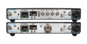
Makito X4 Rugged
Makito X1 Rugged
Haivision EMS
Element manager.
Deliver secure, ultra-low latency video in the most demanding environments with military-grade ISR solutions.

Haivision Media Platform
Iptv system.

Haivision Play
Set-top box.
Makito X H.264

Haivision Play Pro
Mobile player app.
Distribute broadcast channels and live video to browsers, set-top boxes, and mobile devices, across multiple locations.

Haivision SRT Gateway
Ip video gateway, free srt player app.

SRT Video Streaming
Open source protocol.
Reliably stream secure, high-quality, and low latency video with SRT encoders, gateways, and transmitters.
Video Decoder
Transport secure, low latency, and high-quality video with our range of video encoders and transmitters.
- Government & Defense
- Public Safety
- White Papers
- Haivision Podcast
- Case Studies
- Play Pro Settings Tool
- Streaming Calculator
- Documentation
- Video Walls 101
- Streaming Video Glossary
- About Haivision
- Leadership Team
- Investor Relations
- Technology Partners
- Press Releases
- Partner Portal
- SRT Alliance
- Haivision Hub – Sign In
- EN FR DE ES PT

How to Configure SRT Settings on Your Video Encoder for Optimal Performance
Are you new to configuring SRT streams? We’ve put together this quick guide to help you learn the basics of how to configure and tune SRT settings for optimizing stream performance for your specific use case. In this blog post, we’re providing a 7-point checklist for configuring an SRT stream using a Haivision Makito X4 video encoder as a source and a Makito X4 video decoder as the destination device.
Let’s start off with a quick reminder of what SRT is and what it does.
SRT Fundamentals
As the public internet started to gain in availability and bandwidth, more people attempted to leverage it for streaming live video but overcoming issues around packet loss and latency proved extremely challenging. The internet is very unpredictable, and between any two points, bandwidth can vary enormously, as can the rate of packet loss, jitter due to timing issues, and latency depending on distance and routes.
SRT (Secure Reliable Transport) was specifically designed to address these issues and the purpose of the protocol is very simple – to reliably get video content from point A to point B over the internet and protect it with encryption.

SRT enables streamers to tune latency all the way down to 10s of milliseconds for cross-continental video links – a critical feature that enables workflows for interactive, bi-directional interviews and remote production for example.
SRT Statistics: Know Your Network
Not only does SRT enable the secure transport of your video content, it constantly monitors and measures the bandwidth between the two endpoints, providing a whole host of useful statistics, from the number of lost packets to the estimated link bandwidth, latency, and round-trip time.

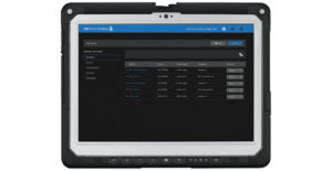
Makito X4 video encoder graphical statistics display
The statistics generated provide valuable insight into your network and stream’s conditions. Armed with a deeper understanding of these statistics, you can better tune and optimize your SRT streaming performance.
SRT Configuration and Tuning Checklist
With your source and destination devices set up – including established call modes (listener, caller, rendezvous) and firewall settings – follow these 7 steps to configure an SRT stream:
#1. Measure the round-trip time (RTT)
Also called round-trip delay, RTT (measured in milliseconds) is the time required for a packet to travel from a source to a specific destination and back again. RTT is used as a guide when configuring bandwidth overhead and latency.
To determine the RTT between two devices, you can use the ping command or, if ping does not work or is not available, set up a test SRT stream and use the RTT value from the statistics page.
If the RTT is <= 20 ms, then use 20 ms for the RTT value. This is because SRT does not respond to events on time scales shorter than 20 ms.
#2. Calculate the packet loss rate
Packet loss rate is a measure of network congestion, expressed as a percentage of packets lost with respect to packets sent. A channel’s packet loss rate drives the SRT latency and bandwidth overhead calculations and can be extracted from iperf statistics.
If using iperf is not possible, set up a test SRT stream, and then use the resent bytes / sent bytes reported on the SRT stream’s statistics page over a 60 second period to calculate the packet loss rate as follows:
Packet loss rate = resent bytes ÷ sent bytes * 100
#3. Calculate the RTT multiplier and bandwidth overhead values
The RTT multiplier is a value used in the calculation of SRT latency. It reflects the relationship between the degree of congestion on a network and the RTT. The bandwidth overhead is the portion of the total bandwidth of a stream that is required for the exchange of SRT control and recovered packets.
It’s worth noting that the range of the RTT multiplier is from 3 to 20. Anything below 3 is too small for SRT to be effective and anything above 20 implies a network with 100% packet loss.
Find the RTT multiplier and bandwidth overhead values that correspond to your measured packet loss rate using the table below:
#4. Calculate SRT Latency
Determine your SRT latency value using the following formula:
SRT latency = RTT multiplier * RTT
If RTT < 20ms, use the minimum SRT latency value in the table above.
#5. Measure the nominal channel capacity
Using the iperf utility measure the nominal channel capacity available to the SRT stream.
If iperf does not work or is not available, set up a test SRT stream and use the max bandwidth or path max bandwidth value from the statistics page.
#6. Determine the stream bitrate
The steam bitrate is the sum of the video, audio, and metadata essence bit rates, plus an SRT protocol overhead. It must the following constraint:
Channel capacity > SRT stream bandwidth * (100 + bandwidth overhead) ÷ 100
If this is not respected, then the video/audio/metadata bitrate must be reduced until it is respected. It’s recommended that a significant amount of headroom be added to cushion against varying channel capacity, so a more conservative constraint would be:
0.75 * channel capacity > SRT stream bandwidth * (100 + bandwidth overhead) ÷ 100
#7. Verify that the SRT stream has been set up correctly
The best way to determine this is to set up a test SRT stream and look at the SRT send buffer graph on the statistics page of the source device. The send buffer value should never exceed the SRT latency bound. If the two plot lines are close, increase the SRT latency
SRT Protocol Technical Overview
For a deeper dive into configuring and tuning SRT for your use case, download the SRT Protocol Technical Overview.
Share this post

Lina Nikols
Lina Nikols is a seasoned content specialist with almost 20 years of combined copywriting and marketing experience. Well versed in writing about a broad range of subjects, from consumer technology to enterprise software solutions, Lina is passionate about creating clear, no-fuss content that zeroes in on the wants and needs of her readers. When she’s not writing or researching, she loves running (very slowly), photography and tea drinking.
- All Encoders & Transmitters
The SRT Protocol
This document specifies Secure Reliable Transport (SRT) protocol. SRT is a user-level protocol over User Datagram Protocol and provides reliability and security optimized for low latency live video streaming, as well as generic bulk data transfer. For this, SRT introduces control packet extension, improved flow control, enhanced congestion control and a mechanism for data encryption. 
Note to Readers
Source for this draft and an issue tracker can be found at https://github.com/haivision/srt-rfc . 
Status of This Memo
This Internet-Draft is submitted in full conformance with the provisions of BCP 78 and BCP 79. 
Internet-Drafts are working documents of the Internet Engineering Task Force (IETF). Note that other groups may also distribute working documents as Internet-Drafts. The list of current Internet-Drafts is at https://datatracker.ietf.org/drafts/current/ . 
Internet-Drafts are draft documents valid for a maximum of six months and may be updated, replaced, or obsoleted by other documents at any time. It is inappropriate to use Internet-Drafts as reference material or to cite them other than as "work in progress." 
This Internet-Draft will expire on 11 July 2024. 
Copyright Notice
Copyright (c) 2024 IETF Trust and the persons identified as the document authors. All rights reserved. 
This document is subject to BCP 78 and the IETF Trust's Legal Provisions Relating to IETF Documents ( https://trustee.ietf.org/license-info ) in effect on the date of publication of this document. Please review these documents carefully, as they describe your rights and restrictions with respect to this document. 
Table of Contents
1. introduction, 1.1. motivation.
The demand for live video streaming has been increasing steadily for many years. With the emergence of cloud technologies, many video processing pipeline components have transitioned from on-premises appliances to software running on cloud instances. While real-time streaming over TCP-based protocols like RTMP [ RTMP ] is possible at low bitrates and on a small scale, the exponential growth of the streaming market has created a need for more powerful solutions. 
To improve scalability on the delivery side, content delivery networks (CDNs) at one point transitioned to segmentation-based technologies like HLS (HTTP Live Streaming) [ RFC8216 ] and DASH (Dynamic Adaptive Streaming over HTTP) [ ISO23009 ] . This move increased the end-to-end latency of live streaming to over few tens of seconds, which makes it unattractive for specific use cases where real-time is important. Over time, the industry optimized these delivery methods, bringing the latency down to few seconds. 
While the delivery side scaled up, improvements to video transcoding became a necessity. Viewers watch video streams on a variety of different devices, connected over different types of networks. Since upload bandwidth from on-premises locations is often limited, video transcoding moved to the cloud. 
RTMP became the de facto standard for contribution over the public Internet. But there are limitations for the payload to be transmitted, since RTMP as a media specific protocol only supports two audio channels and a restricted set of audio and video codecs, lacking support for newer formats such as HEVC [ H.265 ] , VP9 [ VP9 ] , or AV1 [ AV1 ] . 
Since RTMP, HLS and DASH rely on TCP, these protocols can only guarantee acceptable reliability over connections with low RTTs, and can not use the bandwidth of network connections to their full extent due to limitations imposed by congestion control. Notably, QUIC [ RFC9000 ] has been designed to address these problems with HTTP-based delivery protocols in HTTP/3 [ RFC9114 ] . Like QUIC, SRT [ SRTSRC ] uses UDP instead of the TCP transport protocol, but assures more reliable delivery using Automatic Repeat Request (ARQ), packet acknowledgments, end-to-end latency management, etc. 
1.2. Secure Reliable Transport Protocol
Low latency video transmissions across reliable (usually local) IP based networks typically take the form of MPEG-TS [ ISO13818-1 ] unicast or multicast streams using the UDP/RTP protocol, where any packet loss can be mitigated by enabling forward error correction (FEC). Achieving the same low latency between sites in different cities, countries or even continents is more challenging. While it is possible with satellite links or dedicated MPLS [ RFC3031 ] networks, these are expensive solutions. The use of public Internet connectivity, while less expensive, imposes significant bandwidth overhead to achieve the necessary level of packet loss recovery. Introducing selective packet retransmission (reliable UDP) to recover from packet loss removes those limitations. 
Derived from the UDP-based Data Transfer (UDT) protocol [ GHG04b ] , SRT is a user-level protocol that retains most of the core concepts and mechanisms while introducing several refinements and enhancements, including control packet modifications, improved flow control for handling live streaming, enhanced congestion control, and a mechanism for encrypting packets. 
SRT is a transport protocol that enables the secure, reliable transport of data across unpredictable networks, such as the Internet. While any data type can be transferred via SRT, it is ideal for low latency (sub-second) video streaming. SRT provides improved bandwidth utilization compared to RTMP, allowing much higher contribution bitrates over long distance connections. 
As packets are streamed from source to destination, SRT detects and adapts to the real-time network conditions between the two endpoints, and helps compensate for jitter and bandwidth fluctuations due to congestion over noisy networks. Its error recovery mechanism minimizes the packet loss typical of Internet connections. 
To achieve low latency streaming, SRT had to address timing issues. The characteristics of a stream from a source network are completely changed by transmission over the public Internet, which introduces delays, jitter, and packet loss. This, in turn, leads to problems with decoding, as the audio and video decoders do not receive packets at the expected times. The use of large buffers helps, but latency is increased. SRT includes a mechanism to keep a constant end-to-end latency, thus recreating the signal characteristics on the receiver side, and reducing the need for buffering. 
Like TCP, SRT employs a listener/caller model. The data flow is bi-directional and independent of the connection initiation - either the sender or receiver can operate as listener or caller to initiate a connection. The protocol provides an internal multiplexing mechanism, allowing multiple SRT connections to share the same UDP port, providing access control functionality to identify the caller on the listener side. 
Supporting forward error correction (FEC) and selective packet retransmission (ARQ), SRT provides the flexibility to use either of the two mechanisms or both combined, allowing for use cases ranging from the lowest possible latency to the highest possible reliability. 
SRT maintains the ability for fast file transfers introduced in UDT, and adds support for AES encryption. 
2. Terms and Definitions
The key words "MUST", "MUST NOT", "REQUIRED", "SHALL", "SHALL NOT", "SHOULD", "SHOULD NOT", "RECOMMENDED", "NOT RECOMMENDED", "MAY", and "OPTIONAL" in this document are to be interpreted as described in BCP 14 [ RFC2119 ] [ RFC8174 ] when, and only when, they appear in all capitals, as shown here. 
The Secure Reliable Transport protocol described by this document. 
Pseudo-Random Number Generator. 
3. Packet Structure
SRT packets are transmitted as UDP payload [ RFC0768 ] . Every UDP packet carrying SRT traffic contains an SRT header immediately after the UDP header ( Figure 1 ). 
SRT has two types of packets distinguished by the Packet Type Flag: data packet and control packet. 
The structure of the SRT packet is shown in Figure 2 . 
Packet Type Flag. The control packet has this flag set to "1". The data packet has this flag set to "0". 
The timestamp of the packet, in microseconds. The value is relative to the time the SRT connection was established. Depending on the transmission mode ( Section 4.2 ), the field stores the packet send time or the packet origin time. 
A fixed-width field providing the SRT socket ID to which a packet should be dispatched. The field may have the special value "0" when the packet is a connection request. 
3.1. Data Packets
The structure of the SRT data packet is shown in Figure 3 . 
The sequential number of the data packet. Range [0; 2^31 - 1]. 
Packet Position Flag. This field indicates the position of the data packet in the message. The value "10b" (binary) means the first packet of the message. "00b" indicates a packet in the middle. "01b" designates the last packet. If a single data packet forms the whole message, the value is "11b". 
Order Flag. Indicates whether the message should be delivered by the receiver in order (1) or not (0). Certain restrictions apply depending on the data transmission mode used ( Section 4.2 ). 
Key-based Encryption Flag. The flag bits indicate whether or not data is encrypted. The value "00b" (binary) means data is not encrypted. "01b" indicates that data is encrypted with an even key, and "10b" is used for odd key encryption. Refer to Section 6 . The value "11b" is only used in control packets. 
Retransmitted Packet Flag. This flag is clear when a packet is transmitted the first time. The flag is set to "1" when a packet is retransmitted. 
The sequential number of consecutive data packets that form a message (see PP field). 
See Section 3 . 
The payload of the data packet. The length of the data is the remaining length of the UDP packet. 
The message authentication tag (AES-GCM). The field is only present if AES-GCM crypto mode has been negotiated. 
3.2. Control Packets
An SRT control packet has the following structure. 
Control Packet Type. The use of these bits is determined by the control packet type definition. See Table 1 . 
This field specifies an additional subtype for specific packets. See Table 1 . 
The use of this field depends on the particular control packet type. Handshake packets do not use this field. 
The use of this field is defined by the Control Type field of the control packet. 
The types of SRT control packets are shown in Table 1 . The value "0x7FFF" is reserved for a user-defined type. 
3.2.1. Handshake
Handshake control packets (Control Type = 0x0000) are used to exchange peer configurations, to agree on connection parameters, and to establish a connection. 
The Type-specific Information field is unused in the case of the HS message. The Control Information Field (CIF) of a handshake control packet is shown in Figure 5 . 
The handshake version number. Currently used values are 4 and 5. Values greater than 5 are reserved for future use. 
Block cipher family and key size. The values of this field are described in Table 2 . The default value is 0 (no encryption advertised). If neither peer advertises encryption, AES-128 is selected by default (see Section 4.3 ). 
This field is message specific extension related to Handshake Type field. The value MUST be set to 0 except for the following cases. 
(1) If the handshake control packet is the INDUCTION message, this field is sent back by the Listener. (2) In the case of a CONCLUSION message, this field value should contain a combination of Extension Type values. 
For more details, see Section 4.3.1 . 
The sequence number of the very first data packet to be sent. 
Maximum Transmission Unit (MTU) size, in bytes. This value is typically set to 1500 bytes, which is the default MTU size for Ethernet, but can be less. 
The value of this field is the maximum number of data packets allowed to be "in flight" (i.e. the number of sent packets for which an ACK control packet has not yet been received). 
This field indicates the handshake packet type. The possible values are described in Table 4 . For more details refer to Section 4.3 . 
This field holds the ID of the source SRT socket from which a handshake packet is issued. 
Randomized value for processing a handshake. The value of this field is specified by the handshake message type. See Section 4.3 . 
IPv4 or IPv6 address of the packet's sender. The value consists of four 32-bit fields. In the case of IPv4 addresses, fields 2, 3 and 4 are filled with zeroes. 
The value of this field is used to process an integrated handshake. Each extension can have a pair of request and response types. 
The length of the Extension Contents field in four-byte blocks. 
The payload of the extension. 
3.2.1.1. Handshake Extension Message
In a Handshake Extension, the value of the Extension Field of the handshake control packet is defined as 1 for a Handshake Extension request (SRT_CMD_HSREQ in Table 5 ), and 2 for a Handshake Extension response (SRT_CMD_HSRSP in Table 5 ). 
The Extension Contents field of a Handshake Extension Message is structured as follows: 
SRT library version MUST be formed as major * 0x10000 + minor * 0x100 + patch. 
SRT configuration flags (see Section 3.2.1.1.1 ). 
Timestamp-Based Packet Delivery (TSBPD) Delay of the receiver, in milliseconds. Refer to Section 4.5 . 
TSBPD of the sender, in milliseconds. Refer to Section 4.5 . 
3.2.1.1.1. Handshake Extension Message Flags
TSBPDSND flag defines if the TSBPD mechanism ( Section 4.5 ) will be used for sending. 
TSBPDRCV flag defines if the TSBPD mechanism ( Section 4.5 ) will be used for receiving. 
CRYPT flag MUST be set. It is a legacy flag that indicates the party understands KK field of the SRT Packet ( Figure 3 ). 
TLPKTDROP flag should be set if too-late packet drop mechanism will be used during transmission. See Section 4.6 . 
PERIODICNAK flag set indicates the peer will send periodic NAK packets. See Section 4.8.2 . 
REXMITFLG flag MUST be set. It is a legacy flag that indicates the peer understands the R field of the SRT DATA Packet ( Figure 3 ). 
STREAM flag identifies the transmission mode ( Section 4.2 ) to be used in the connection. If the flag is set, the buffer mode ( Section 4.2.2 ) is used. Otherwise, the message mode ( Section 4.2.1 ) is used. 
PACKET_FILTER flag indicates if the peer supports packet filter. 
3.2.1.2. Key Material Extension Message
If an encrypted connection is being established, the Key Material (KM) is first transmitted as a Handshake Extension message. This extension is not supplied for unprotected connections. The purpose of the extension is to let peers exchange and negotiate encryption-related information to be used to encrypt and decrypt the payload of the stream. 
The extension can be supplied with the Handshake Extension Type field set to either SRT_CMD_KMREQ or SRT_CMD_KMRSP (see Table 5 in Section 3.2.1 ). For more details refer to Section 4.3 . 
The KM message is placed in the Extension Contents. See Section 3.2.2 for the structure of the KM message. 
In case of SRT_CMD_KMRSP the Extension Length value can be equal to 1 (meaning 4 bytes). It is an indication of encryption failure. In this case the Extension Content has a different format, Figure 7 . 
Key Material State of the peer: 
NOTE: In the descriptions below, "peer" refers to the remote SRT side sending the KM response, and "agent" refers to the local side interpreting the KM response. 
0: unsecured (the peer will encrypt the payload, while the agent has not declared any encryption), 
3: no secret (the peer does not have the key to decrypt the incoming payload), 
4: bad secret (the peer has the wrong key and can't decrypt the incoming payload), 
5: bad crypto mode (the peer expects to use a different cryptographic mode). Since protocol v1.6. 
3.2.1.3. Stream ID Extension Message
The Stream ID handshake extension message can be used to identify the stream content. The Stream ID value can be free-form, but there is also a recommended convention that can be used to achieve interoperability. 
The Stream ID handshake extension message has SRT_CMD_SID extension type (see Table 5 . The extension contents are a sequence of UTF-8 characters. The maximum allowed size of the StreamID extension is 512 bytes. 
The Extension Contents field holds a sequence of UTF-8 characters (see Figure 8 ). The maximum allowed size of the StreamID extension is 512 bytes. The actual size is determined by the Extension Length field ( Figure 5 ), which defines the length in four byte blocks. If the actual payload is less than the declared length, the remaining bytes are set to zeros. 
The content is stored as 32-bit little endian words. 
3.2.1.4. Group Membership Extension
The Group Membership handshake extension is reserved for the future and is going to be used to allow multipath SRT connections. 
The identifier of a group whose members include the sender socket that is making a connection. The target socket that is interpreting GroupID SHOULD belong to the corresponding group on the target side. If such a group does not exist, the target socket MAY create it. 
Group type, as per SRT_GTYPE_ enumeration: 
0: undefined group type, 
1: broadcast group type, 
2: main/backup group type, 
3: balancing group type, 
4: multicast group type (reserved for future use). 
Special flags mostly reserved for the future. See Figure 10 . 
Special value with interpretation depending on the Type field value: 
Not used with broadcast group type, 
Defines the link priority for main/backup group type, 
Not yet defined for any other cases (reserved for future use). 
When set, defines synchronization on message numbers, otherwise transmission is synchronized on sequence numbers. 
3.2.2. Key Material
The purpose of the Key Material Message is to let peers exchange encryption-related information to be used to encrypt and decrypt the payload of the stream. 
This message can be supplied in two possible ways: 
as a Handshake Extension (see Section 3.2.1.2 ) 
in the Content Information Field of the User-Defined control packet (described below). 
When the Key Material is transmitted as a control packet, the Control Type field of the SRT packet header is set to User-Defined Type (see Table 1 ), the Subtype field of the header is set to SRT_CMD_KMREQ for key-refresh request and SRT_CMD_KMRSP for key-refresh response ( Table 5 ). The KM Refresh mechanism is described in Section 6.1.6 . 
The structure of the Key Material message is illustrated in Figure 11 . 
This is a fixed-width field that is reserved for future usage. 
This is a fixed-width field that indicates the KM message version: 
1: Initial KM message format version. 
This is a fixed-width field that indicates the Packet Type: 
0: Reserved 
1: Media Stream Message (MSmsg) 
2: Keying Material Message (KMmsg) 
7: Reserved to discriminate MPEG-TS packet (0x47=sync byte). 
This is a fixed-width field that contains the signature ‘HAI‘ encoded as a PnP Vendor ID [ PNPID ] (in big-endian order). 
This is a fixed-width field reserved for flag extension or other usage. 
This is a fixed-width field that indicates which SEKs (odd and/or even) are provided in the extension: 
00b: No SEK is provided (invalid extension format); 
01b: Even key is provided; 
10b: Odd key is provided; 
11b: Both even and odd keys are provided. 
This is a fixed-width field for specifying the KEK index (big-endian order) was used to wrap (and optionally authenticate) the SEK(s). The value 0 is used to indicate the default key of the current stream. Other values are reserved for the possible use of a key management system in the future to retrieve a cryptographic context. 
0: Default stream associated key (stream/system default) 
1..255: Reserved for manually indexed keys. 
This is a fixed-width field for specifying encryption cipher and mode: 
0: None or KEKI indexed crypto context; 
1: AES-ECB (Reserved, not supported); 
2: AES-CTR [ SP800-38A ] ; 
3: AES-CBC (Reserved, not supported); 
4: AES-GCM (Galois Counter Mode), starting from v1.6.0. 
If AES-GCM is set as the cipher, AES-GCM MUST also be set as the message authentication code algorithm (the Auth field). 
This is a fixed-width field for specifying a message authentication code (MAC) algorithm: 
1: AES-GCM, starting from v1.6.0. 
If AES-GCM is selected as the MAC algorithm, it MUST also be selected as the cipher. 
This is a fixed-width field for describing the stream encapsulation: 
0: Unspecified or KEKI indexed crypto context 
1: MPEG-TS/UDP 
2: MPEG-TS/SRT. 
This is a fixed-width field reserved for future use. 
This is a fixed-width field for specifying salt length SLen in bytes divided by 4. Can be zero if no salt/IV present. The only valid length of salt defined is 128 bits. 
This is a fixed-width field for specifying SEK length in bytes divided by 4. Size of one key even if two keys present. MUST match the key size specified in the Encryption Field of the handshake packet Table 2 . 
This is a variable-width field that complements the keying material by specifying a salt key. 
This is a variable-width field for specifying Wrapped key(s), where n = (KK + 1)/2 and the size of the wrap field is ((n * KLen) + 8) bytes. 
64-bit Integrity Check Vector(AES key wrap integrity). This field is used to detect if the keys were unwrapped properly. If the KEK in hand is invalid, validation fails and unwrapped keys are discarded. 
This field identifies an odd or even SEK. If only one key is present, the bit set in the KK field tells which SEK is provided. If both keys are present, then this field is eSEK (even key) and it is followed by odd key oSEK. The length of this field is calculated as KLen * 8. 
This field with the odd key is present only when the message carries the two SEKs (identified by he KK field). 
3.2.3. Keep-Alive
Keep-alive control packets are sent after a certain timeout from the last time any packet (Control or Data) was sent. The purpose of this control packet is to notify the peer to keep the connection open when no data exchange is taking place. 
The default timeout for a keep-alive packet to be sent is 1 second. 
An SRT keep-alive packet is formatted as follows: 
The packet type value of a keep-alive control packet is "1". 
The control type value of a keep-alive control packet is "1". 
This field is reserved for future definition. 
Keep-alive controls packet do not contain Control Information Field (CIF). 
3.2.4. ACK (Acknowledgment)
Acknowledgment (ACK) control packets are used to provide the delivery status of data packets. By acknowledging the reception of data packets up to the acknowledged packet sequence number, the receiver notifies the sender that all prior packets were received or, in the case of live streaming ( Section 4.2 , Section 7.1 ), preceding missing packets (if any) were dropped as too late to be delivered ( Section 4.6 ). 
ACK packets may also carry some additional information from the receiver like the estimates of RTT, RTT variance, link capacity, receiving speed, etc. The CIF portion of the ACK control packet is expanded as follows: 
The packet type value of an ACK control packet is "1". 
The control type value of an ACK control packet is "2". 
This field contains the sequential number of the full acknowledgment packet starting from 1, except in the case of Light ACKs and Small ACKs, where this value is 0 (see below). 
This field contains the sequence number of the last data packet being acknowledged plus one. In other words, if it the sequence number of the first unacknowledged packet. 
RTT value, in microseconds, estimated by the receiver based on the previous ACK/ACKACK packet pair exchange. 
The variance of the RTT estimate, in microseconds. 
Available size of the receiver's buffer, in packets. 
The rate at which packets are being received, in packets per second. 
Estimated bandwidth of the link, in packets per second. 
Estimated receiving rate, in bytes per second. 
There are several types of ACK packets: 
A Full ACK control packet is sent every 10 ms and has all the fields of Figure 14 . 
A Light ACK control packet includes only the Last Acknowledged Packet Sequence Number field. The Type-specific Information field should be set to 0. 
A Small ACK includes the fields up to and including the Available Buffer Size field. The Type-specific Information field should be set to 0. 
The sender only acknowledges the receipt of Full ACK packets (see Section 3.2.8 ). 
The Light ACK and Small ACK packets are used in cases when the receiver should acknowledge received data packets more often than every 10 ms. This is usually needed at high data rates. It is up to the receiver to decide the condition and the type of ACK packet to send (Light or Small). The recommendation is to send a Light ACK for every 64 packets received. 
3.2.5. NAK (Negative Acknowledgement or Loss Report)
Negative acknowledgment (NAK) control packets are used to signal failed data packet deliveries. The receiver notifies the sender about lost data packets by sending a NAK packet that contains a list of sequence numbers for those lost packets. 
An SRT NAK packet is formatted as follows: 
The packet type value of a NAK control packet is "1". 
The control type value of a NAK control packet is "3". 
A single value or a range of lost packets sequence numbers. See packet sequence number coding in Appendix A . 
3.2.6. Congestion Warning
The Congestion Warning control packet is reserved for future use. Its purpose is to allow a receiver to signal a sender that there is congestion happening at the receiving side. The expected behaviour is that upon receiving this packet the sender slows down its sending rate by increasing the minimum inter-packet sending interval by a discrete value (posited to be 12.5%). 
Note that the conditions for a receiver to issue this type of packet are not yet defined. 
The packet type value of a Congestion Warning control packet is "1". 
The control type value of a Congestion Warning control packet is "4". 
3.2.7. Shutdown
Shutdown control packets are used to initiate the closing of an SRT connection. 
An SRT shutdown control packet is formatted as follows: 
The packet type value of a shutdown control packet is "1". 
The control type value of a shutdown control packet is "5". 
Shutdown control packets do not contain Control Information Field (CIF). 
3.2.8. ACKACK (Acknowledgement of Acknowledgement)
Acknowledgement of Acknowledgement (ACKACK) control packets are sent to acknowledge the reception of a Full ACK and used in the calculation of the round-trip time by the SRT receiver. 
An SRT ACKACK control packet is formatted as follows: 
The packet type value of an ACKACK control packet is "1". 
The control type value of an ACKACK control packet is "6". 
This field contains the Acknowledgement Number of the full ACK packet the reception of which is being acknowledged by this ACKACK packet. 
ACKACK control packets do not contain Control Information Field (CIF). 
3.2.9. Message Drop Request
A Message Drop Request control packet is sent by the sender to the receiver when a retransmission of an unacknowledged packet (forming a whole or a part of a message) which is not present in the sender's buffer is requested. This may happen, for example, when a TTL parameter (passed in the sending function) triggers a timeout for retransmitting one or more lost packets which constitute parts of a message, causing these packets to be removed from the sender's buffer. 
The sender notifies the receiver that it must not wait for retransmission of this message. Note that a Message Drop Request control packet is not sent if the Too Late Packet Drop mechanism ( Section 4.6 ) causes the sender to drop a message, as in this case the receiver is expected to drop it anyway. 
A Message Drop Request contains the message number and corresponding range of packet sequence numbers which form the whole message. If the sender does not already have in its buffer the specific packet or packets for which retransmission was requested, then it is unable to restore the message number. In this case the Message Number field must be set to zero, and the receiver should drop packets in the provided packet sequence number range. 
The packet type value of a Drop Request control packet is "1". 
The control type value of a Drop Request control packet is "7". 
The identifying number of the message requested to be dropped. See the Message Number field in Section 3.1 . 
The sequence number of the first packet in the message. 
The sequence number of the last packet in the message. 
3.2.10. Peer Error
The Peer Error control packet is sent by a receiver when a processing error (e.g. write to disk failure) occurs. This informs the sender of the situation and unblocks it from waiting for further responses from the receiver. 
The sender receiving this type of control packet must unblock any sending operation in progress. 
NOTE : This control packet is only used if the File Transfer Congestion Control ( Section 5.2 ) is enabled. 
The packet type value of a Peer Error control packet is "1". 
The control type value of a Peer Error control packet is "8". 
Peer error code. At the moment the only value defined is 4000 - file system error. 
4. SRT Data Transmission and Control
This section describes key concepts related to the handling of control and data packets during the transmission process. 
After the handshake and exchange of capabilities is completed, packet data can be sent and received over the established connection. To fully utilize the features of low latency and error recovery provided by SRT, the sender and receiver must handle control packets, timers, and buffers for the connection as specified in this section. 
4.1. Stream Multiplexing
Multiple SRT sockets may share the same UDP socket so that the packets received to this UDP socket will be correctly dispatched to those SRT sockets they are currently destined. 
During the handshake, the parties exchange their SRT Socket IDs. These IDs are then used in the Destination SRT Socket ID field of every control and data packet (see Section 3 ). 
4.2. Data Transmission Modes
There are two data transmission modes supported by SRT: message mode ( Section 4.2.1 ) and buffer mode ( Section 4.2.2 ). These are the modes originally defined in the UDT protocol [ GHG04b ] . 
As SRT has been mainly designed for live video and audio streaming, its main and default transmission mode is message mode with certain settings applied ( Section 7.1 ). 
Besides live streaming, SRT maintains the ability for fast file transfers introduced in UDT ( Section 7.2 ). The usage of both message and buffer modes is possible in this case. 
Best practices and configuration tips for both use cases can be found in Section 7 . 
4.2.1. Message Mode
When the STREAM flag of the handshake Extension Message Section 3.2.1.1 is set to 0, the protocol operates in Message mode, characterized as follows: 
Every packet has its own Packet Sequence Number. 
One or several consecutive SRT data packets can form a message. 
All the packets belonging to the same message have a similar message number set in the Message Number field. 
The first packet of a message has the first bit of the Packet Position Flags ( Section 3.1 ) set to 1. The last packet of the message has the second bit of the Packet Position Flags set to 1. Thus, a PP equal to "11b" indicates a packet that forms the whole message. A PP equal to "00b" indicates a packet that belongs to the inner part of the message. 
The concept of the message in SRT comes from UDT [ GHG04b ] . In this mode, a single sending instruction passes exactly one piece of data that has boundaries (a message). This message may span multiple UDP packets and multiple SRT data packets. The only size limitation is that it shall fit as a whole in the buffers of the sender and the receiver. Although internally all operations (e.g., ACK, NAK) on data packets are performed independently, an application must send and receive the whole message. Until the message is complete (all packets are received) the application will not be allowed to read it. 
When the Order Flag of a data packet is set to 1, this imposes a sequential reading order on messages. An Order Flag set to 0 allows an application to read messages that are already fully available, before any preceding messages that may have some packets missing. 
4.2.2. Buffer Mode
Buffer mode is negotiated during the handshake by setting the STREAM flag of the handshake Extension Message Flags ( Section 3.2.1.1.1 ) to 1. 
In this mode, consecutive packets form one continuous stream that can be read with portions of any size. 
4.3. Handshake Messages
SRT uses UDP as an underlying connectionless transport protocol. SRT is a connection-oriented protocol. It embraces the concepts of "connection" and "session". Every SRT session starts with the connection phase, where peers exchange configuration parameters and relevant information by the means of SRT handshake control packets. 
SRT versions prior to v1.3.0 use version 4 of the handshaking procedure. HS version 5 is used starting from SRT v1.3.0.\ HS version 4 is not described in this specification. SRT implementations MUST support HS version 5, but MAY not support HS v4. 
An SRT connection is characterized by the fact that it is: 
first engaged by a handshake process, 
maintained as long as any packets are being exchanged in a timely manner, and 
considered closed when a party receives the appropriate SHUTDOWN command from its peer (connection closed by the foreign host), or when it receives no packets at all for some predefined time (connection broken on timeout). 
SRT supports two connection modes: 
Caller-Listener, where one side waits for the other to initiate a connection; 
Rendezvous, where both sides attempt to initiate a connection. 
The handshake is performed between two parties: "Initiator" and "Responder" in the following order: 
Initiator starts an extended SRT handshake process and sends appropriate SRT extended handshake requests. 
Responder expects the SRT extended handshake requests to be sent by the Initiator and sends SRT extended handshake responses back. 
There are three basic types of SRT handshake extensions that are exchanged in the handshake: 
Handshake Extension Message exchanges the basic SRT information; 
Key Material Exchange exchanges the wrapped stream encryption key (used only if an encryption is requested). 
Stream ID extension exchanges some stream-specific information that can be used by the application to identify an incoming stream connection. 
The Initiator and Responder roles are assigned depending on the connection mode. 
For Caller-Listener connections: the Caller is the Initiator, the Listener is the Responder. For Rendezvous connections: the Initiator and Responder roles are assigned based on the initial data interchange during the handshake. 
The Handshake Type field in the Handshake Structure (see Figure 5 ) indicates the handshake message type. 
Caller-Listener handshake exchange has the following order of Handshake Types: 
Caller to Listener: INDUCTION Request 
Listener to Caller: INDUCTION Response (reports cookie) 
Caller to Listener: CONCLUSION Request (uses previously returned cookie) 
Listener to Caller: CONCLUSION Response (confirms connection established). 
Rendezvous handshake exchange has the following order of Handshake Types: 
Both peers after starting the connection: WAVEAHAND with a cookie. 
After receiving the above message from the peer: CONCLUSION 
After receiving the above message from the peer: AGREEMENT. 
When a connection process has failed before either party can send the CONCLUSION handshake, the Handshake Type field will contain the appropriate error value for the rejected connection. See the list of error codes in Table 7 . 
The specification of the cipher family and block size is decided by the data Sender. When the transmission is bidirectional, this value MUST be agreed upon at the outset because when both are set the Responder wins. For Caller-Listener connections it is reasonable to set this value on the Listener only. In the case of Rendezvous the only reasonable approach is to decide upon the correct value from the different sources and to set it on both parties (note that AES-128 is the default). 
4.3.1. Caller-Listener Handshake
This section describes the handshaking process where a Listener is waiting for an incoming Handshake request on a bound UDP port from a Caller. The process has two phases: induction and conclusion. 
4.3.1.1. The Induction Phase
The INDUCTION phase serves only to set a cookie on the Listener so that it doesn't allocate resources, thus mitigating a potential DoS attack that might be perpetrated by flooding the Listener with handshake commands. 
4.3.1.1.1. The Induction Request
The Caller begins by sending the INDUCTION handshake which contains the following significant fields: 
Destination SRT Socket ID: 0. 
HS Version: MUST always be 4. 
Encryption Field: 0. 
Extension Field: 2 
Handshake Type: INDUCTION 
SRT Socket ID: SRT Socket ID of the Caller 
SYN Cookie: 0. 
There MUST be no HS extensions. 
The Destination SRT Socket ID of the SRT packet header in this message is 0, which is interpreted as a connection request. 
The handshake version number is set to 4 in this initial handshake. This is due to the initial design of SRT that was to be compliant with the UDT protocol [ GHG04b ] on which it is based. 
4.3.1.1.2. The Induction Response
The Listener responds with the following: 
HS Version: 5. 
Encryption Field: Advertised cipher family and block size. 
Extension Field: SRT magic code 0x4A17. 
SRT Socket ID: Socket ID of the Listener 
SYN Cookie: a cookie that is crafted based on host, port and current time with 1 minute accuracy to avoid SYN flooding attack [ RFC4987 ] . 
At this point the Listener still does not know if the Caller is SRT or UDT, and it responds with the same set of values regardless of whether the Caller is SRT or UDT. 
A legacy UDT party completely ignores the values reported in the HS Version and the Handshake Type field.\ It is, however, interested in the SYN Cookie value, as this must be passed to the next phase. It does interpret these fields, but only in the "conclusion" message. 
4.3.1.2. The Conclusion Phase
4.3.1.2.1. the conclusion request.
The SRT caller receives the Induction Response from the SRT listener. The SRT caller MUST check the Induction response from the SRT listener. 
If the HS Version value is 5, the response came from SRT, and the handshake version 5 procedure is performed as covered below.\ If the HS Version value is 4, the legacy handshake procedure can be applied if supported. The procedure is deprecated and is not covered here. The caller MAY reject the connection with the SRT_REJ_VERSION reason. In this case there is nothing to send to the SRT listener, as there is no connection established at this point. 
The Extension Flags field MUST contain the magic value 0x4A17. If it does not, the connection MUST be rejected with rejection reason SRT_REJ_ROGUE . This is, among other things, a contingency for the case when someone, in an attempt to extend UDT independently, increases the HS Version value to 5 and tries to test it against SRT. In this case there is nothing to send to the SRT listener, as there is no connection established at this point. 
If the Encryption Flag field is set to 0 (not advertised), the caller MAY advertise its own cipher and key length. If the induction response already advertises a certain value in the Encryption Flag, the caller MAY accept it or force its own value. It is RECOMMENDED that if a caller will be sending the content, then it SHOULD force its own value. If it expects to receive content from the SRT listener, then is it RECOMMENDED that it accepts the value advertised in the Encryption Flag field. 
An alternative behavior MAY be for a caller to take the longer key length in such cases. 
TODO: Receiver TSBPD Delay, Sender TSBPD Delay. 
The SRT Caller forms a Conclusion Request. The following values of a Handshake packet MUST be set by the compliant Caller: 
Handshake Type: CONCLUSION. 
SRT Socket ID: Socket ID of the Caller. 
SYN Cookie: the Listener's cookie from the induction response. 
Encryption Flags: advertised cipher family and block size. 
Extension Flags: a set of flags that define the extensions provided in the handshake. 
The Handshake Extension Message Section 3.2.1.1 MUST be present in the conclusion response. 
4.3.1.2.2. The Conclusion Response
The SRT Listener receives the conclusion request. If the values of the conclusion request are in any way NOT acceptable on the SRT Listener side, the connection MUST be rejected by sending a conclusion response with the Handshake Type field carrying the rejection reason ( Table 7 ). 
TODO: latency value. Special value 0. 
TODO: Incorrect? The only case when the Listener can have precedence over the Caller is the advertised Cipher Family and Block Size (see Table 2 ) in the Encryption Field of the Handshake. 
The value for latency is always agreed to be the greater of those reported by each party. 
Destination SRT Socket ID: the SRT Socket ID field value of the previously received conclusion request. 
There is no "negotiation" at this point. 
4.3.2. Rendezvous Handshake
The Rendezvous process uses a state machine. It is slightly different from UDT Rendezvous handshake [ GHG04b ] , although it is still based on the same message request types. 
The states of a party are Waving ("Wave A Hand"), Conclusion and Agreement. The Waving stage is intended to exchange cookie values, perform the cookie contest and deduce the role of each party: initiator or responder. 
4.3.2.1. Cookie Contest
The cookie contest is intended to determine the connection role of a peer. When one party's cookie value is greater (with certain conditions, see below) than its peer's, it wins the cookie contest and becomes Initiator (the other party becomes the Responder). 
The intent is to let the side with the greater cookie value become the Initiator (the other party becomes the Responder). However, with a special handling of the higher bit of the difference. 
4.3.2.2. The Waving State
Both parties start in a Waving state. In the Waving state, the parties wishing to connect -- Bob and Alice -- each send a WAVEAHAND handshake packet with the fields set to the following values: 
HS Version: 5 
Type: Extension field: 0, Encryption field: advertised "PBKEYLEN" 
Handshake Type: WAVEAHAND ( Table 4 ) 
SRT Socket ID: socket ID of the party (HS sender). 
SYN Cookie: Created based on host/port and current time. 
HS Extensions: none. 
Legacy HS Version 4 clients do not look at the HS Version value, whereas HS Version 5 clients can detect version 5. The parties only continue with the HS Version 5 Rendezvous process when HS Version is set to 5 for both. Otherwise the process continues exclusively according to HS Version 4 rules [ GHG04b ] . Implementations MUST support HS Version 5, and MAY not support HS Version 4. 
The WAVEAHAND Handshake packet SHOULD not have extensions. 
With SRT Handshake Version 5 Rendezvous, both parties create a cookie for a process called the "cookie contest". This is necessary for the assignment of Initiator and Responder roles. Each party generates a cookie value (a 32-bit number) based on the host, port, and current time with 1 minute accuracy. This value is scrambled using an MD5 sum calculation. The cookie values are then compared with one another. 
Since it is impossible to have two sockets on the same machine bound to the same NIC and port and operating independently, it is virtually impossible that the parties will generate identical cookies. However, this situation may occur if an application tries to "connect to itself" - that is, either connects to a local IP address, when the socket is bound to INADDR_ANY, or to the same IP address to which the socket was bound. If the cookies are identical (for any reason), the connection will not be made until new, unique cookies are generated (after a delay of up to one minute). In the case of an application "connecting to itself", the cookies will always be identical, and so the connection will never be established. 
If there is no response from a peer the WAVEAHAND handshake SHOULD be repeated every 250 ms until a connection timeout expires. The connection timeout value is defined by the implementation. 
If a WAVEAHAND packet is received from the peer during a CONCLUSION handshake, the state is transitioned to the Attention state. 
4.3.2.3. Conclusion
In the Conclusion state each peer has received and now knows the other's cookie value. Thus each peer can perform the Cookie Contest operation (compare both cookie values according to Section 4.3.2.1 ) and thereby determine its role. The determination of the Handshake Role (Initiator or Responder) is essential for further processing. 
Initiator replies with a Conclusion request handshake: 
Extension field: appropriate flags. 
Encryption field: advertised PBKEYLEN 
Required Handshake Extension: HS Extension Message ( Section 3.2.1.1 ) with HS Extension Type SRT_CMD_HSREQ. 
Other handshake extensions are allowed. 
If encryption is on, the Initiator (Bob) will use either his own cipher family and block size or the one received from Alice (if she has advertised those values). 
The Responder responds with a Conclusion or a WAVEAHAND handshake without extensions until it receives the Conclusion Request from the peer: 
Extension field: 0. 
Encryption field: advertised PBKEYLEN. 
Handshake extensions are NOT allowed. 
TODO: What to do if WAVEAHAND or AGREEMENT or else is received in this stage? Repeat conclusion response but not more often that every 250 ms. 
4.3.2.4. Initiated
Alice receives Bob's CONCLUSION message. While at this point she also performs the "cookie contest" operation, the outcome will be the same. She switches to the "fine" state, and sends: - Version: 5 - Appropriate extension flags and encryption flags - Handshake Type: CONCLUSION 
Both parties always send extension flags at this point, which will contain HSREQ if the message comes from an Initiator, or HSRSP if it comes from a Responder. If the Initiator has received a previous message from the Responder containing an advertised cipher family and block size in the encryption flags field, it will be used as the key length for key generation sent next in the KMREQ extension. 
4.3.2.5. Serial Handshake Flow
In the serial handshake flow, one party is always first, and the other follows. That is, while both parties are repeatedly sending WAVEAHAND messages, at some point one party - let's say Alice - will find she has received a WAVEAHAND message before she can send her next one, so she sends a CONCLUSION message in response. Meantime, Bob (Alice's peer) has missed Alice's WAVEAHAND messages, so that Alice's CONCLUSION is the first message Bob has received from her. 
This process can be described easily as a series of exchanges between the first and following parties (Alice and Bob, respectively): 
Initially, both parties are in the waving state. Alice sends a handshake message to Bob: 
Version: 5 
Handshake Type: WAVEAHAND 
SRT Socket ID: Alice's socket ID 
While Alice does not yet know if she is sending this message to a Version 4 or Version 5 peer, the values from these fields would not be interpreted by the Version 4 peer when the Handshake Type is WAVEAHAND. 
Bob receives Alice's WAVEAHAND message, switches to the "attention" state. Since Bob now knows Alice's cookie, he performs a "cookie contest" (compares both cookie values). If Bob's cookie is greater than Alice's, he will become the Initiator. Otherwise, he will become the Responder. 
The resolution of the Handshake Role (Initiator or Responder) is essential for further processing. 
Then Bob responds: 
Extension field: appropriate flags if Initiator, otherwise 0 
If Bob is the Initiator and encryption is on, he will use either his own cipher family and block size or the one received from Alice (if she has advertised those values). 
Alice receives Bob's CONCLUSION message. While at this point she also performs the "cookie contest", the outcome will be the same. She switches to the "fine" state, and sends: 
Appropriate extension flags and encryption flags 
Bob receives Alice's CONCLUSION message, and then does one of the following (depending on Bob's role): 
If Bob is the Initiator (Alice's message contains HSRSP), he: 
switches to the "connected" state, and 
sends Alice a message with Handshake Type AGREEMENT, but containing no SRT extensions (Extension Flags field should be 0). 
If Bob is the Responder (Alice's message contains HSREQ), he: 
switches to "initiated" state, 
sends Alice a message with Handshake Type CONCLUSION that also contains extensions with HSRSP, and 
awaits a confirmation from Alice that she is also connected (preferably by AGREEMENT message). 
Alice receives the above message, enters into the "connected" state, and then does one of the following (depending on Alice's role): 
If Alice is the Initiator (received CONCLUSION with HSRSP), she sends Bob a message with Handshake Type = AGREEMENT. 
If Alice is the Responder, the received message has Handshake Type AGREEMENT and in response she does nothing. 
At this point, if Bob was an Initiator, he is connected already. If he was a Responder, he should receive the above AGREEMENT message, after which he switches to the "connected" state. In the case where the UDP packet with the agreement message gets lost, Bob will still enter the "connected" state once he receives anything else from Alice. If Bob is going to send, however, he has to continue sending the same CONCLUSION until he gets the confirmation from Alice. 
4.3.2.6. Parallel Handshake Flow
The chances of the parallel handshake flow are very low, but still it may occur if the handshake messages with WAVEAHAND are sent and received by both peers at precisely the same time. 
The resulting flow is very much like Bob's behaviour in the serial handshake flow, but for both parties. Alice and Bob will go through the same state transitions: 
In the Attention state they know each other's cookies, so they can assign roles. In contrast to serial flows, which are mostly based on request-response cycles, here everything happens completely asynchronously: the state switches upon reception of a particular handshake message with appropriate contents (the Initiator MUST attach the HSREQ extension, and Responder MUST attach the HSRSP extension). 
Here is how the parallel handshake flow works, based on roles and states: 
(1) Initiator 
Receives WAVEAHAND message, 
Switches to Attention, 
Sends CONCLUSION + HSREQ. 
Attention 
Receives CONCLUSION message which 
either contains no extensions, then switches to Initiated, still sends CONCLUSION + HSREQ; or 
contains HSRSP extension, then switches to Connected, sends AGREEMENT. 
Initiated 
Receives CONCLUSION message, which 
either contains no extensions, then REMAINS IN THIS STATE, still sends CONCLUSION + HSREQ; or 
Connected 
May receive CONCLUSION and respond with AGREEMENT, but normally by now it should already have received payload packets. 
(2) Responder 
Sends CONCLUSION message (with no extensions). 
Receives CONCLUSION message with HSREQ. This message might contain no extensions, in which case the party SHALL simply send the empty CONCLUSION message, as before, and remain in this state. 
Switches to Initiated and sends CONCLUSION message with HSRSP. 
Receives: 
CONCLUSION message with HSREQ, then responds with CONCLUSION with HSRSP and remains in this state; 
AGREEMENT message, then responds with AGREEMENT and switches to Connected; 
Payload packet, then responds with AGREEMENT and switches to Connected. 
Is not expecting to receive any handshake messages anymore. The AGREEMENT message is always sent only once or per every final CONCLUSION message. 
Note that any of these packets may be missing, and the sending party will never become aware. The missing packet problem is resolved this way: 
If the Responder misses the CONCLUSION + HSREQ message, it simply continues sending empty CONCLUSION messages. Only upon reception of CONCLUSION + HSREQ it does respond with CONCLUSION + HSRSP. 
If the Initiator misses the CONCLUSION + HSRSP response from the Responder, it continues sending CONCLUSION + HSREQ. The Responder MUST always respond with CONCLUSION + HSRSP when the Initiator sends CONCLUSION + HSREQ, even if it has already received and interpreted it. 
When the Initiator switches to the Connected state it responds with a AGREEMENT message, which may be missed by the Responder. Nonetheless, the Initiator may start sending data packets because it considers itself connected - it does not know that the Responder has not yet switched to the Connected state. Therefore it is exceptionally allowed that when the Responder is in the Initiated state and receives a data packet (or any control packet that is normally sent only between connected parties) over this connection, it may switch to the Connected state just as if it had received a AGREEMENT message. 
If the the Initiator has already switched to the Connected state it will not bother the Responder with any more handshake messages. But the Responder may be completely unaware of that (having missed the AGREEMENT message from the Initiator). Therefore it does not exit the connecting state, which means that it continues sending CONCLUSION + HSRSP messages until it receives any packet that will make it switch to the Connected state (normally AGREEMENT). Only then does it exit the connecting state and the application can start transmission. 
4.4. SRT Buffer Latency
The SRT sender and receiver have buffers to store packets. 
On the sender, latency is the time that SRT holds a packet to give it a chance to be delivered successfully while maintaining the rate of the sender at the receiver. If an acknowledgment (ACK) is missing or late for more than the configured latency, the packet is dropped from the sender buffer. A packet can be retransmitted as long as it remains in the buffer for the duration of the latency window. On the receiver, packets are delivered to an application from a buffer after the latency interval has passed. This helps to recover from potential packet losses. See Section 4.5 , Section 4.6 for details. 
Latency is a value, in milliseconds, that can cover the time to transmit hundreds or even thousands of packets at high bitrate. Latency can be thought of as a window that slides over time, during which a number of activities take place, such as the reporting of acknowledged packets (ACKs) ( Section 4.8.1 ) and unacknowledged packets (NAKs) ( Section 4.8.2 ). 
Latency is configured through the exchange of capabilities during the extended handshake process between initiator and responder. The Handshake Extension Message ( Section 3.2.1.1 ) has TSBPD delay information, in milliseconds, from the SRT receiver and sender. The latency for a connection will be established as the maximum value of latencies proposed by the initiator and responder. 
4.5. Timestamp-Based Packet Delivery
The goal of the SRT Timestamp-Based Packet Delivery (TSBPD) mechanism is to reproduce the output of the sending application (e.g., encoder) at the input of the receiving application (e.g., decoder) in the case of live streaming ( Section 4.2 , Section 7.1 ). It attempts to reproduce the timing of packets committed by the sending application to the SRT sender. This allows packets to be scheduled for delivery by the SRT receiver, making them ready to be read by the receiving application (see Figure 21 ). 
The SRT receiver, using the timestamp of the SRT data packet header, delivers packets to a receiving application with a fixed minimum delay from the time the packet was scheduled for sending on the SRT sender side. Basically, the sender timestamp in the received packet is adjusted to the receiver’s local time (compensating for the time drift or different time zones) before releasing the packet to the application. Packets can be withheld by the SRT receiver for a configured receiver delay. A higher delay can accommodate a larger uniform packet drop rate, or a larger packet burst drop. Packets received after their "play time" are dropped if the Too-Late Packet Drop feature is enabled ( Section 4.6 ). For example, in the case of live video streaming, TSBPD and Too-Late Packet Drop mechanisms allow to intentionally drop those packets that were lost and have no chance to be retransmitted before their play time. Thus, SRT provides a fixed end-to-end latency of the stream. 
The packet timestamp, in microseconds, is relative to the SRT connection creation time. Packets are inserted based on the sequence number in the header field. The origin time, in microseconds, of the packet is already sampled when a packet is first submitted by the application to the SRT sender unless explicitly provided. The TSBPD feature uses this time to stamp the packet for first transmission and any subsequent retransmission. This timestamp and the configured SRT latency ( Section 4.4 ) control the recovery buffer size and the instant that packets are delivered at the destination (the aforementioned "play time" which is decided by adding the timestamp to the configured latency). 
It is worth mentioning that the use of the packet sending time to stamp the packets is inappropriate for the TSBPD feature, since a new time (current sending time) is used for retransmitted packets, putting them out of order when inserted at their proper place in the stream. 
Figure 21 illustrates the key latency points during the packet transmission with the TSBPD feature enabled. 
The main packet states shown in Figure 21 are the following: 
"Scheduled for sending": the packet is committed by the sending application, stamped and ready to be sent; 
"Sent": the packet is passed to the UDP socket and sent; 
"Received": the packet is received and read from the UDP socket; 
"Scheduled for delivery": the packet is scheduled for the delivery and ready to be read by the receiving application. 
It is worth noting that the round-trip time (RTT) of an SRT link may vary in time. However the actual end-to-end latency on the link becomes fixed and is approximately equal to (RTT_0/2 + SRT Latency) once the SRT handshake exchange happens, where RTT_0 is the actual value of the round-trip time during the SRT handshake exchange (the value of the round-trip time once the SRT connection has been established). 
The value of sending delay depends on the hardware performance. Usually it is relatively small (several microseconds) in contrast to RTT_0/2 and SRT latency which are measured in milliseconds. 
4.5.1. Packet Delivery Time
Packet delivery time is the moment, estimated by the receiver, when a packet should be delivered to the upstream application. The calculation of packet delivery time (PktTsbpdTime) is performed upon receiving a data packet according to the following formula: 
TsbpdTimeBase is the time base that reflects the time difference between local clock of the receiver and the clock used by the sender to timestamp packets being sent (see Section 4.5.1.1 ); 
PKT_TIMESTAMP is the data packet timestamp, in microseconds; 
TsbpdDelay is the receiver’s buffer delay (or receiver’s buffer latency, or SRT Latency). This is the time, in milliseconds, that SRT holds a packet from the moment it has been received till the time it should be delivered to the upstream application; 
Drift is the time drift used to adjust the fluctuations between sender and receiver clock, in microseconds. 
SRT Latency (TsbpdDelay) should be a buffer time large enough to cover the unexpectedly extended RTT time, and the time needed to retransmit the lost packet. The value of minimum TsbpdDelay is negotiated during the SRT handshake exchange and is equal to 120 milliseconds. The recommended value of TsbpdDelay is 3-4 times RTT. 
It is worth noting that TsbpdDelay limits the number of packet retransmissions to a certain extent making it impossible to retransmit packets endlessly. This is important for the case of live streaming ( Section 4.2 , Section 7.1 ). 
4.5.1.1. TSBPD Time Base Calculation
The initial value of TSBPD time base (TsbpdTimeBase) is calculated at the moment of the second handshake request is received as follows: 
where T_NOW is the current time according to the receiver clock; HSREQ_TIMESTAMP is the handshake packet timestamp, in microseconds. 
The value of TsbpdTimeBase is approximately equal to the initial one-way delay of the link RTT_0/2, where RTT_0 is the actual value of the round-trip time during the SRT handshake exchange. 
During the transmission process, the value of TSBPD time base may be adjusted in two cases: 
During the TSBPD wrapping period. The TSBPD wrapping period happens every 01:11:35 hours. This time corresponds to the maximum timestamp value of a packet (MAX_TIMESTAMP). MAX_TIMESTAMP is equal to 0xFFFFFFFF, or the maximum value of 32-bit unsigned integer, in microseconds ( Section 3 ). The TSBPD wrapping period starts 30 seconds before reaching the maximum timestamp value of a packet and ends once the packet with timestamp within (30, 60) seconds interval is delivered (read from the buffer). The updated value of TsbpdTimeBase will be recalculated as follows: 
By drift tracer. See Section 4.7 for details. 
4.6. Too-Late Packet Drop
The Too-Late Packet Drop (TLPKTDROP) mechanism allows the sender to drop packets that have no chance to be delivered in time, and allows the receiver to skip missing packets that have not been delivered in time. The timeout of dropping a packet is based on the TSBPD mechanism ( Section 4.5 ). 
When the TLPKTDROP mechanism is enabled, a packet is considered "too late" to be delivered and may be dropped by the sender if the packet timestamp is older than TLPKTDROP_THRESHOLD. 
TLPKTDROP_THRESHOLD is related to SRT latency ( Section 4.4 ). For the Too-Late Packet Drop mechanism to function effectively, it is recommended that a value higher than the SRT latency is used. This will allow the SRT receiver to drop missing packets first while the sender drops packets if a proper response is not received from the peer in time (e.g., due to severe congestion). The recommended threshold value is 1.25 times the SRT latency value. 
Note that the SRT sender keeps packets for at least 1 second in case the latency is not high enough for a large RTT (that is, if TLPKTDROP_THRESHOLD is less than 1 second). 
When enabled on the receiver, the receiver drops packets that have not been delivered or retransmitted in time, and delivers the subsequent packets to the application when it is their time to play. 
In pseudo-code, the algorithm of reading from the receiver buffer is the following: 
where T_NOW is the current time according to the receiver clock. 
When a receiver encounters the situation where the next packet to be played was not successfully received from the sender, the receiver will "skip" this packet and send a fake ACK packet ( Section 4.8.1 ). To the sender, this fake ACK is a real ACK, and so it just behaves as if the packet had been received. This facilitates the synchronization between SRT sender and receiver. The fact that a packet was skipped remains unknown by the sender. It is recommended that skipped packets are recorded in the statistics on the SRT receiver. 
The TLPKTDROP mechanism can be turned off to always ensure a clean delivery. However, a lost packet can simply pause a delivery for some longer, potentially undefined time, and cause even worse tearing for the player. Setting SRT latency higher will help much more in the event that TLPKTDROP causes packet drops too often. 
4.7. Drift Management
When the sender enters "connected" status it tells the application there is a socket interface that is transmitter-ready. At this point the application can start sending data packets. It adds packets to the SRT sender's buffer at a certain input rate, from which they are transmitted to the receiver at scheduled times. 
A synchronized time is required to keep proper sender/receiver buffer levels, taking into account the time zone and round-trip time (up to 2 seconds for satellite links). Considering addition/subtraction round-off, and possibly unsynchronized system times, an agreed-upon time base drifts by a few microseconds every minute. The drift may accumulate over many days to a point where the sender or receiver buffers will overflow or deplete, seriously affecting the quality of the video. SRT has a time management mechanism to compensate for this drift. 
When a packet is received, SRT determines the difference between the time it was expected and its timestamp. The timestamp is calculated on the receiver side. The RTT tells the receiver how much time it was supposed to take. SRT maintains a reference between the time at the leading edge of the send buffer's latency window and the corresponding time on the receiver (the present time). This allows to convert packet timestamp to the local receiver time. Based on this time, various events (packet delivery, etc.) can be scheduled. 
The receiver samples time drift data and periodically calculates a packet timestamp correction factor, which is applied to each data packet received by adjusting the inter-packet interval. When a packet is received it is not given right away to the application. As time advances, the receiver knows the expected time for any missing or dropped packet, and can use this information to fill any "holes" in the receive queue with another packet (see Section 4.5 ). 
It is worth noting that the period of sampling time drift data is based on a number of packets rather than time duration to ensure enough samples, independently of the media stream packet rate. The effect of network jitter on the estimated time drift is attenuated by using a large number of samples. The actual time drift being very slow (affecting a stream only after many hours) does not require a fast reaction. 
The receiver uses local time to be able to schedule events — to determine, for example, if it is time to deliver a certain packet right away. The timestamps in the packets themselves are just references to the beginning of the session. When a packet is received (with a timestamp from the sender), the receiver makes a reference to the beginning of the session to recalculate its timestamp. The start time is derived from the local time at the moment that the session is connected. A packet timestamp equals "now" minus "StartTime", where the latter is the point in time when the socket was created. 
4.8. Acknowledgement and Lost Packet Handling
To enable the Automatic Repeat reQuest of data packet retransmissions, a sender stores all sent data packets in its buffer. 
The SRT receiver periodically sends acknowledgments (ACKs) for the received data packets so that the SRT sender can remove the acknowledged packets from its buffer ( Section 4.8.1 ). Once the acknowledged packets are removed, their retransmission is no longer possible and presumably not needed. 
Upon receiving the full acknowledgment (ACK) control packet, the SRT sender SHOULD acknowledge its reception to the receiver by sending an ACKACK control packet with the sequence number of the full ACK packet being acknowledged. 
The SRT receiver also sends NAK control packets to notify the sender about the missing packets ( Section 4.8.2 ). The sending of a NAK packet can be triggered immediately after a gap in sequence numbers of data packets is detected. In addition, a Periodic NAK report mechanism can be used to send NAK reports periodically. The NAK packet in that case will list all the packets that the receiver considers being lost up to the moment the Periodic NAK report is sent. 
Upon reception of the NAK packet, the SRT sender prioritizes retransmissions of lost packets over the regular data packets to be transmitted for the first time. 
The retransmission of the missing packet is repeated until the receiver acknowledges its receipt, or if both peers agree to drop this packet ( Section 4.6 ). 
4.8.1. Packet Acknowledgement (ACKs, ACKACKs)
At certain intervals (see below), the SRT receiver sends an acknowledgment (ACK) that causes the acknowledged packets to be removed from the SRT sender's buffer. 
An ACK control packet contains the sequence number of the packet immediately following the latest in the list of received packets. Where no packet loss has occurred up to the packet with sequence number n, an ACK would include the sequence number (n + 1). 
An ACK (from a receiver) will trigger the transmission of an ACKACK (by the sender), with almost no delay. The time it takes for an ACK to be sent and an ACKACK to be received is the RTT. The ACKACK tells the receiver to stop sending the ACK position because the sender already knows it. Otherwise, ACKs (with outdated information) would continue to be sent regularly. Similarly, if the sender does not receive an ACK, it does not stop transmitting. 
There are two conditions for sending an acknowledgment. A full ACK is based on a timer of 10 milliseconds (the ACK period or synchronization time interval SYN). For high bitrate transmissions, a "light ACK" can be sent, which is an ACK for a sequence of packets. In a 10 milliseconds interval, there are often so many packets being sent and received that the ACK position on the sender does not advance quickly enough. To mitigate this, after 64 packets (even if the ACK period has not fully elapsed) the receiver sends a light ACK. A light ACK is a shorter ACK (SRT header and one 32-bit field). It does not trigger an ACKACK. 
When a receiver encounters the situation where the next packet to be played was not successfully received from the sender, it will "skip" this packet (see Section 4.6 ) and send a fake ACK. To the sender, this fake ACK is a real ACK, and so it just behaves as if the packet had been received. This facilitates the synchronization between SRT sender and receiver. The fact that a packet was skipped remains unknown by the sender. Skipped packets are recorded in the statistics on the SRT receiver. 
4.8.2. Packet Retransmission (NAKs)
The SRT receiver sends NAK control packets to notify the sender about the missing packets. The NAK packet sending can be triggered immediately after a gap in sequence numbers of data packets is detected. 
The SRT sender maintains a list of lost packets (loss list) that is built from NAK reports. When scheduling packet transmission, it looks to see if a packet in the loss list has priority and sends it if so. Otherwise, it sends the next packet scheduled for the first transmission list. Note that when a packet is transmitted, it stays in the buffer in case it is not received by the SRT receiver. 
NAK packets are processed to fill in the loss list. As the latency window advances and packets are dropped from the sending queue, a check is performed to see if any of the dropped or resent packets are in the loss list, to determine if they can be removed from there as well so that they are not retransmitted unnecessarily. 
There is a counter for the packets that are resent. If there is no ACK for a packet, it will stay in the loss list and can be resent more than once. Packets in the loss list are prioritized. 
If packets in the loss list continue to block the send queue, at some point this will cause the send queue to fill. When the send queue is full, the sender will begin to drop packets without even sending them the first time. An encoder (or other application) may continue to provide packets, but there's no place for them, so they will end up being thrown away. 
This condition where packets are unsent does not happen often. There is a maximum number of packets held in the send buffer based on the configured latency. Older packets that have no chance to be retransmitted and played in time are dropped, making room for newer real-time packets produced by the sending application. See Section 4.5 , Section 4.6 for details. 
In addition to the regular NAKs, the Periodic NAK report mechanism can be used to send NAK reports periodically. The NAK packet in that case will have all the packets that the receiver considers being lost at the time of sending the Periodic NAK report. 
SRT Periodic NAK reports are sent with a period of (RTT + 4 * RTTVar) / 2 (so called NAKInterval), with a 20 milliseconds floor, where RTT and RTTVar are defined in Section 4.10 . A NAK control packet contains a compressed list of the lost packets. Therefore, only lost packets are retransmitted. By using NAKInterval for the NAK reports period, it may happen that lost packets are retransmitted more than once, but it helps maintain low latency in the case where NAK packets are lost. 
An ACKACK tells the receiver to stop sending the ACK position because the sender already knows it. Otherwise, ACKs (with outdated information) would continue to be sent regularly. 
An ACK serves as a ping, with a corresponding ACKACK pong, to measure RTT. The time it takes for an ACK to be sent and an ACKACK to be received is the RTT. Each ACK has a number. A corresponding ACKACK has that same number. The receiver keeps a list of all ACKs in a queue to match them. Unlike a full ACK, which contains the current RTT and several other values in the Control Information Field (CIF) ( Section 3.2.4 ), a light ACK just contains the sequence number. All control messages are sent directly and processed upon reception, but ACKACK processing time is negligible (the time this takes is included in the round-trip time). 
4.9. Bidirectional Transmission Queues
Once an SRT connection is established, both peers can send data packets simultaneously. 
4.10. Round-Trip Time Estimation
Round-trip time (RTT) in SRT is estimated during the transmission of data packets based on a difference in time between an ACK packet is sent out and a corresponding ACKACK packet is received back by the SRT receiver. 
An ACK sent by the receiver triggers an ACKACK from the sender with minimal processing delay. The ACKACK response is expected to arrive at the receiver roughly one RTT after the corresponding ACK was sent. 
The SRT receiver records the time when an ACK is sent out. The ACK carries a unique sequence number (independent of the data packet sequence number). The corresponding ACKACK also carries the same sequence number. Upon receiving the ACKACK, SRT calculates the RTT by comparing the difference between the ACKACK arrival time and the ACK departure time. In the following formula, RTT is the current value that the receiver maintains and rtt is the recent value that was just calculated from an ACK/ACKACK pair: 
RTT variance (RTTVar) is obtained as follows: 
where abs() means an absolute value. 
Both RTT and RTTVar are measured in microseconds. The initial value of RTT is 100 milliseconds, RTTVar is 50 milliseconds. 
The round-trip time (RTT) calculated by the receiver as well as the RTT variance (RTTVar) are sent with the next full acknowledgement packet (see Section 3.2.4 ). Note that the first ACK in an SRT session might contain an initial RTT value of 100 milliseconds, because the early calculations may not be precise. 
The sender always gets the RTT from the receiver. It does not have an analog to the ACK/ACKACK mechanism, i.e. it can not send a message that guarantees an immediate return without processing. Upon an ACK reception, the SRT sender updates its own RTT and RTTVar values using the same formulas as above, in which case rtt is the most recent value it receives, i.e., carried by an incoming ACK. 
Note that an SRT socket can both send and receive data packets. RTT and RTTVar are updated by the socket based on algorithms for the sender (using ACK packets) and for the receiver (using ACK/ACKACK pairs). When an SRT socket receives data, it updates its local RTT and RTTVar, which can be used for its own sender as well. 
5. SRT Packet Pacing and Congestion Control
SRT provides certain mechanisms for exchanging feedback on the state of packet transmission between sender and receiver. Every 10 milliseconds the receiving side sends acknowledgement (ACK) packets ( Section 3.2.4 ) to the sender that include the latest values of RTT, RTT variance, available buffer size, receiving rate, and estimated link capacity. Similarly, NAK packets ( Section 3.2.5 ) from the receiver inform the sender of any packet loss during the transmission, triggering an appropriate response. These mechanisms provide a solid background for the integration of various congestion control algorithms in the SRT protocol. 
As SRT is designed both for live streaming and file transmission ( Section 4.2 ), there are two groups of congestion control algorithms defined in SRT: Live Congestion Control (LiveCC), and File Transfer Congestion Control (FileCC). 
5.1. SRT Packet Pacing and Live Congestion Control (LiveCC)
To ensure smooth video playback on a receiving peer during live streaming, SRT must control the sender's buffer level to prevent overfill and depletion. The pacing control module is designed to send packets as fast as they are submitted by a video application while maintaining a relatively stable buffer level. While this looks like a simple problem, the details of the Automatic Repeat Request (ARQ) behaviour between input and output of the SRT sender add some complexity. 
SRT needs a certain amount of bandwidth overhead in order to have space for the sender to insert packets for retransmission with minimum impact on the output rate of the main packet transmission. 
This balance is achieved by adjusting the maximum allowed bandwidth MAX_BW ( Section 5.1.1 ) which limits the bandwidth usage by SRT. The MAX_BW value is used by the Live Congestion Control (LiveCC) module to calculate the minimum interval between consecutive sent packets PKT_SND_PERIOD. In principle, the space between packets determines where retransmissions can be inserted, and the overhead represents the available margin. There is an empiric calculation that defines the interval, in microseconds, between two packets to give a certain bitrate. It is a function of the average packet payload (which includes video, audio, etc.) and the configured maximum bandwidth (MAX_BW). See Section 5.1.2 for details. 
In the case of live streaming, the sender is allowed to drop packets that cannot be delivered in time ( Section 4.6 ). 
The combination of pacing control and Live Congestion Control (LiveCC), based on the input rate and an overhead for packets retransmission, helps avoid congestion during fluctuations of the source bitrate. 
During live streaming over highly variable networks, fairness can be achieved by controlling the bitrate of the source encoder at the input of the SRT sender. SRT sender can provide a variety of network related statistics, such as RTT estimate, packet loss level, the number of packets dropped, etc., to the encoder which can be used for making decisions and adjusting the bitrate in real time. 
5.1.1. Configuring Maximum Bandwidth
There are several ways of configuring maximum bandwidth (MAX_BW): 
MAXBW_SET mode: Set the value explicitly. 
The recommended default value is 1 Gbps. The default value is set only for live streaming. 
Note that this static setting is not well-suited to a variable input, like when you change the bitrate on an encoder. Each time the input bitrate is configured on the encoder, MAX_BW should also be reconfigured. 
INPUTBW_SET mode: Set the SRT sender's input rate (INPUT_BW) and overhead (OVERHEAD). 
In this mode, SRT calculates the maximum bandwidth as follows: 
Note that INPUTBW_SET mode reduces to the MAXBW_SET mode and the same restrictions apply. 
INPUTBW_ESTIMATED mode: Measure the SRT sender's input rate internally and set the overhead (OVERHEAD). 
In this mode, SRT adjusts the value of maximum bandwidth each time it gets the updated estimate of the input rate EST_INPUT_BW: 
Note that the units of MAX_BW, INPUT_BW, and EST_INPUT_BW are bytes per second. OVERHEAD is defined in %. 
INPUTBW_ESTIMATED mode is recommended for setting the maximum bandwidth (MAX_BW) as it follows the fluctuations in SRT sender's input rate. However, there are certain considerations that should be taken into account. 
In INPUTBW_SET mode, SRT takes as an input the rate that had been configured as the expected output rate of an encoder (in terms of bitrate for the packets including audio and overhead). But it is normal for an encoder to occasionally overshoot. At low bitrate, sometimes an encoder can be too optimistic and will output more bits than expected. Under these conditions, SRT packets would not go out fast enough because the configured bandwidth limitation would be too low. 
This is mitigated by calculating the bitrate internally (INPUTBW_ESTIMATED mode). SRT examines the packets being submitted and calculates the input rate as a moving average. However, this introduces a bit of a delay based on the content. It also means that if an encoder encounters black screens or still frames, this would dramatically lower the bitrate being measured, which would in turn reduce the SRT output rate. And then, when the video picks up again, the input rate rises sharply. SRT would not start up again fast enough on output because of the time it takes to measure the speed. Packets might be accumulated in the SRT's sender buffer and delayed as a result, causing them to arrive too late at the decoder, and possible drops by the receiver. 
The following table shows a summary of the bandwidth configuration modes and the variables that need to be set (v) or ignored (-): 
5.1.2. SRT's Default LiveCC Algorithm
The main goal of the SRT's default LiveCC algorithm is to adjust the minimum allowed packet sending period PKT_SND_PERIOD (and, as a result, the maximum allowed sending rate) during transmission based on the average packet payload size (AvgPayloadSize) and maximum bandwidth (MAX_BW). 
On the sender side, there are three events that the LiveCC algorithm reacts to: (1) sending a data packet, (2) receiving an acknowledgement (ACK) packet, and (3) a timeout event as described below. 
(1) On sending a data packet (either original or retransmitted), update the value of average packet payload size (AvgPayloadSize): 
where PacketPayloadSize is the payload size of a sent data packet, in bytes; the initial value of AvgPayloadSize is equal to the maximum allowed packet payload size, which cannot be larger than 1456 bytes. 
(2) On an acknowledgement (ACK) packet reception: 
Step 1. Calculate SRT packet size (PktSize) as the sum of average payload size (AvgPayloadSize) and SRT header size ( Section 3 ), in bytes. 
Step 2. Calculate the minimum allowed packet sending period (PKT_SND_PERIOD) as: 
where MAX_BW is the configured maximum bandwidth which limits the bandwidth usage by SRT, in bytes per second; PKT_SND_PERIOD is measured in microseconds. 
(3) On a retransmission timeout (RTO) event, follow the same steps as described in method (1) above. 
RTO is the amount of time within which an acknowledgement is expected after a data packet is sent out. If there is no ACK after this amount of time has elapsed, a timeout event is triggered. Since SRT only acknowledges every SYN time ( Section 4.8.1 ), the value of retransmission timeout is defined as follows: 
where RTT is the round-trip time estimate, in microseconds, and RTTVar is the variance of RTT estimate, in microseconds, reported by the receiver and smoothed at the sender side (see Section 3.2.4 , Section 4.10 ). Here and throughout the current section, smoothing means applying an exponentially weighted moving average (EWMA). 
Continuous timeout should increase the RTO value. In SRT, a counter (RexmitCount) is used to track the number of continuous timeouts: 
On the receiver side, when a loss report is sent, the sending interval of periodic NAK reports ( Section 4.8.2 ) is updated as follows: 
where RTT and RTTVar are receiver's estimates (see Section 3.2.4 , Section 4.10 ). The minimum value of NAKInterval is set to 20 milliseconds in order to avoid sending periodic NAK reports too often under low latency conditions. 
5.2. File Transfer Congestion Control (FileCC)
For file transfer ( Section 4.2 ), any known congestion control algorithm like CUBIC [ RFC8312 ] or BBR [ BBR ] can be applied, including SRT's default FileCC algorithm described below. 
5.2.1. SRT's Default FileCC Algorithm
SRT's default FileCC algorithm is a modified version of the UDT native congestion control algorithm [ GuAnAO ] , [ GHG04b ] designed for a bulk data transfer over networks with a large bandwidth-delay product (BDP). It is a hybrid Additive Increase Multiplicative Decrease (AIMD) algorithm, hence it adjusts both congestion window size (CWND_SIZE) and packet sending period (PKT_SND_PERIOD). The units of measurement for CWND_SIZE and PKT_SND_PERIOD are packets and microseconds, respectively. 
The algorithm controls sending rate by tuning the packet sending period (i.e. how often packets are sent out). The sending rate is increased upon receipt of an acknowledgement (ACK), and decreased when receiving a loss report (negative acknowledgement, or NAK). Only full ACKs, not light ACKs ( Section 4.8.1 ), trigger an increase in the sending rate. 
SRT congestion control has two phases: "Slow Start" and "Congestion Avoidance". In the slow start phase the congestion control module probes the network to determine available bandwidth and the target sending rate for the next (operational) phase, which is congestion avoidance. In this phase, if there is no congestion detected via loss reports, the sending rate is gradually increased. Conversely, if a network congestion is detected, the algorithm decreases the sending rate to reduce subsequent packet loss. The slow start phase runs exactly once at the beginning of a connection, and stops when a packet loss occurs, when the congestion window size reaches its maximum value, or on a timeout event. 
The detailed algorithm behaviour at both phases is described in Section 5.2.1.1 and Section 5.2.1.2 , respectively. 
As with LiveCC, SRT's default FileCC algorithm reacts to three events: (1) sending a data packet, (2) receiving an acknowledgement (ACK) packet, and (3) a timeout event. These are described below as they apply to the congestion control phases. 
5.2.1.1. Slow Start
During the slow start phase, the packet sending period PKT_SND_PERIOD is kept at 1 microsecond in order to send packets as fast as possible, but not at an infinite rate. The initial value of the congestion window size (CWND_SIZE) is set to 16 packets. CWND_SIZE has an upper threshold, which is the maximum allowed congestion window size (MAX_CWND_SIZE), so that even if there is no packet loss, the slow start phase has to stop at a certain point. The threshold can be set to the maximum receiver buffer size (12 MB). 
(1) On an acknowledgement (ACK) packet reception: 
Step 1. If the interval since the last time the sending rate was either increased or kept (LastRCTime) is less than RC_INTERVAL: 
a. Keep the sending rate at the same level; 
where currTime is the current time, in microseconds; LastRCTime is the last time the sending rate was either increased, or kept, in microseconds. 
Step 2. Update the value of LastRCTime to the current time: 
Step 3. The size of congestion window CWND_SIZE is increased by the difference in sequence numbers of the data packet being acknowledged ACK_SEQNO and the last acknowledged data packet LAST_ACK_SEQNO: 
Step 4. The sequence number of the last acknowledged data packet LAST_ACK_SEQNO is updated as follows: 
Step 5. If the congestion window size CWND_SIZE calculated at Step 3 is greater than the upper threshold MAX_CWND_SIZE, slow start phase ends. Set the packet sending period PKT_SND_PERIOD as follows: 
RECEIVING_RATE is the rate at which packets are being received, in packets per second, reported by the receiver and smoothed at the sender side (see Section 3.2.4 , Section 5.2.1.3 ); 
RTT is the round-trip time estimate, in microseconds, reported by the receiver and smoothed at the sender side (see Section 3.2.4 , Section 4.10 ); 
RC_INTERVAL is the fixed rate control interval, in microseconds. RC_INTERVAL of SRT is SYN, or synchronization time interval, which is 0.01 second. An ACK in SRT is sent every fixed time interval. The maximum and default ACK time interval is SYN. See Section 4.8.1 for details. 
(2) On a loss report (NAK) packet reception: 
Slow start phase ends; 
Set the packet sending period PKT_SND_PERIOD as described in Step 5 of section (1) above. 
(3) On a retransmission timeout (RTO) event: 
5.2.1.2. Congestion Avoidance
Once the slow start phase ends, the algorithm enters the congestion avoidance phase and behaves as described below. 
Step 3. Set the congestion window size to: 
Step 4. If there is packet loss reported by the receiver (bLoss=True): 
a. Keep the value of PKT_SND_PERIOD at the same level; 
b. Set the value of bLoss to False; 
bLoss flag is equal to True if a packet loss has happened since the last sending rate increase. Initial value: False. 
Step 5. If there is no packet loss reported by the receiver (bLoss=False), calculate PKT_SND_PERIOD as follows: 
LastDecPeriod is the value of PKT_SND_PERIOD right before the last sending rate decrease has happened (on a loss report (NAK) packet reception), in microseconds. The initial value of LastDecPeriod is set to 1 microsecond; 
EST_LINK_CAPACITY is the estimated link capacity reported by the receiver within an ACK packet and smoothed at the sender side ( Section 5.2.1.3 ), in packets per second; 
B is the estimated available bandwidth, in packets per second; 
S is the SRT packet size (in terms of IP payload) in bytes. SRT treats 1500 bytes as a standard packet size. 
A detailed explanation of the formulas used to calculate the increase in sending rate can be found in [ GuAnAO ] . UDT's available bandwidth estimation has been modified to take into account the bandwidth registered at the moment of packet loss, since the estimated link capacity reported by the receiver may overestimate the actual link capacity significantly. 
Step 6. If the value of maximum bandwidth MAX_BW defined in Section 5.1 is set, limit the value of PKT_SND_PERIOD to the minimum allowed period, if necessary: 
Note that in the case of file transmission the the maximum allowed bandwidth (MAX_BW) for SRT can be defined. This limits the minimum possible interval between packets sent. Only the usage of MAXBW_SET mode is possible ( Section 5.1.1 ). In contrast with live streaming, there is no default value set for MAX_BW, and the transmission rate is not limited if not set explicitly. 
Step 1. Set the value of flag bLoss equal to True. 
Step 2. If the current loss ratio estimated by the sender is less than 2%: 
b. Update the value of LastDecPeriod: 
This modification has been introduced to increase the algorithm tolerance to a random packet loss specific for public networks, but not related to the absence of available bandwidth. 
Step 3. If sequence number of a packet being reported as lost is greater than the largest sequence number has been sent so far (LastDecSeq), i.e. this NAK starts a new congestion period: 
a. Set the value of LastDecPeriod to the current packet sending period PKT_SND_PERIOD; 
b. Increase the value of packet sending period: 
c. Update AvgNAKNum: 
d. Reset NAKCount and DecCount values to 1; 
e. Record the current largest sent sequence number LastDecSeq; 
f. Compute DecRandom to a random (uniform distribution) number between 1 and AvgNAKNum. If DecRandom < 1: DecRandom = 1; 
AvgNAKNum is the average number of NAKs during a congestion period. Initial value: 0; 
NAKCount is the number of NAKs received so far in the current congestion period. Initial value: 0; 
DecCount means the number of times that the sending rate has been decreased during the congestion period. Initial value: 0; 
DecRandom is a random number used to decide if the rate should be decreased or not for the following NAKs (not the first one) during the congestion period. DecRandom is a random number between 1 and the average number of NAKs per congestion period (AvgNAKNum). 
Congestion period is defined as the time between two NAKs in which the biggest lost packet sequence number carried in the NAK is greater than the LastDecSeq. 
The coefficients used in the formulas above have been slightly modified to reduce the amount by which the sending rate decreases. 
Step 4. If DecCount <= 5, and NAKCount == DecCount * DecRandom: 
a. Update SND period: SND = 1.03 * SND; 
b. Increase DecCount and NAKCount by 1; 
c. Record the current largest sent sequence number (LastDecSeq). 
5.2.1.3. Link Capacity and Receiving Rate Estimation
Estimates of link capacity and receiving rate, in packets/bytes per second, are calculated at the receiver side during file transmission ( Section 4.2 ). It is worth noting that the receiving rate estimate, while available during the entire data transmission period, is used only during the slow start phase of the congestion control algorithm ( Section 5.2.1.1 ). The latest estimate obtained before the end of the slow start period is used by the sender as a reference maximum speed to continue data transmission without further congestion. Link capacity is estimated all the time and used primarily (as well as packet loss ratio and other protocol statistics) for sending rate adjustments during the transmission process. 
As each data packet arrives, the receiver records the time delta with respect to the arrival of the previous data packet, which is used to estimate bandwidth and receiving speed (delivery rate). This and other control information is communicated to the sender by means of acknowledgment (ACK) packets sent every 10 milliseconds. At the sender side, upon receiving a new value, an exponentially weighted moving average (EWMA) is applied to update the latest estimate maintained at the sender side. 
It is important to note that for bandwidth estimation only data probing packets are taken into account, while all data packets (both data and data probing) are used for estimating receiving speed. Data probing refers to the use of the packet pairs technique, whereby pairs of probing packets are sent to a server back-to-back, thus making it possible to measure the minimum interval in receiving consecutive packets. 
The detailed description of models used to estimate link capacity and receiving rate can be found in [ GuAnAO ] , [ GHG04b ] . 
6. Encryption
This section describes the encryption mechanism that protects the payload of SRT streams. Based on standard cryptographic algorithms, the mechanism allows an efficient stream cipher with a key establishment method. 
6.1. Overview
SRT implements encryption using AES [ AES ] in counter mode (AES-CTR) [ SP800-38A ] with a short-lived key to encrypt and decrypt the media stream. The AES-CTR cipher is suitable for continuous stream encryption that permits decryption from any point, without access to start of the stream (random access), and for the same reason tolerates packet loss. It also offers strong confidentiality when the counter is managed properly. 
6.1.1. Encryption Scope
SRT encrypts only the payload of SRT data packets ( Section 3.1 ), while the header is left unencrypted. The unencrypted header contains the Packet Sequence Number field used to keep the synchronization of the cipher counter between the encrypting sender and the decrypting receiver. No constraints apply to the payload of SRT data packets as no padding of the payload is required by counter mode ciphers. 
6.1.2. AES Counter
The counter for AES-CTR is the size of the cipher's block, i.e. 128 bits. It is derived from a 128-bit sequence consisting of 
a block counter in the least significant 16 bits which counts the blocks in a packet; 
a packet index, based on the packet sequence number in the SRT header, in the next 32 bits; 
eighty zeroed bits. 
The upper 112 bits of this sequence are XORed with an Initialization Vector (IV) to produce a unique counter for each crypto block. The IV is derived from the Salt provided in the Keying Material ( Section 3.2.2 ): 
6.1.3. Stream Encrypting Key (SEK)
The key used for AES-CTR encryption is called the "Stream Encrypting Key" (SEK). It is used for up to 2^25 packets with further rekeying. The short-lived SEK is generated by the sender using a pseudo-random number generator (PRNG), and transmitted within the stream, wrapped with another longer-term key, the Key Encrypting Key (KEK), using a known AES key wrap protocol. 
For connection-oriented transport such as SRT, there is no need to periodically transmit the short-lived key since no additional party can join a stream in progress. The keying material is transmitted within the connection handshake packets, and for a short period when rekeying occurs. 
6.1.4. Key Encrypting Key (KEK)
The Key Encrypting Key (KEK) is derived from a secret (passphrase) shared between the sender and the receiver. The KEK provides access to the Stream Encrypting Key, which in turn provides access to the protected payload of SRT data packets. The KEK has to be at least as long as the SEK. 
The KEK is generated by a password-based key generation function (PBKDF2) [ RFC8018 ] , using the passphrase, a number of iterations (2048), a keyed-hash (HMAC-SHA1) [ RFC2104 ] , and a key length value (KLen). The PBKDF2 function hashes the passphrase to make a long string, by repetition or padding. The number of iterations is based on how much time can be given to the process without it becoming disruptive. 
6.1.5. Key Material Exchange
The KEK is used to generate a wrap [ RFC3394 ] that is put in a key material (KM) message by the initiator of a connection (i.e. caller in caller-listener handshake and initiator in the rendezvous handshake, see Section 4.3 ) to send to the responder (listener). The KM message contains the key length, the salt (one of the arguments provided to the PBKDF2 function), the protocol being used (e.g. AES-256) and the AES counter (which will eventually change, see Section 6.1.6 ). 
On the other side, the responder attempts to decode the wrap to obtain the Stream Encrypting Key. In the protocol for the wrap there is a padding, which is a known template, so the responder knows from the KM that it has the right KEK to decode the SEK. The SEK (generated and transmitted by the initiator) is random, and cannot be known in advance. The KEK formula is calculated on both sides, with the difference that the responder gets the key length (KLen) from the initiator via the key material (KM). It is the initiator who decides on the configured length. The responder obtains it from the material sent by the initiator. 
The responder returns the same KM message to show that it has the same information as the initiator, and that the encoded material will be decrypted. If the responder does not return this status, this means that it does not have the SEK. All incoming encrypted packets received by the responder will be lost (undecrypted). Even if they are transmitted successfully, the receiver will be unable to decrypt them, and so packets will be dropped. All data packets coming from responder will be unencrypted. 
6.1.6. KM Refresh
The short lived SEK is regenerated for cryptographic reasons when a pre-determined number of packets has been encrypted. The KM refresh period is determined by the implementation. The receiver knows which SEK (odd or even) was used to encrypt the packet by means of the KK field of the SRT Data Packet ( Section 3.1 ). 
There are two variables used to determine the KM Refresh timing: 
KM Refresh Period specifies the number of packets to be sent before switching to the new SEK. 
KM Pre-Announcement Period specifies when a new key is announced in a number of packets before key switchover. The same value is used to determine when to decommission the old key after switchover. 
The recommended KM Refresh Period is after 2^25 packets encrypted with the same SEK are sent. The recommended KM Pre-Announcement Period is 4000 packets (i.e. a new key is generated, wrapped, and sent at 2^25 minus 4000 packets; the old key is decommissioned at 2^25 plus 4000 packets). 
Even and odd keys are alternated during transmission the following way. The packets with the earlier key #1 (let it be the odd key) will continue to be sent. The receiver will receive the new key #2 (even), then decrypt and unwrap it. The receiver will reply to the sender if it is able to understand. Once the sender gets to the 2^25th packet using the odd key (key #1), it will then start to send packets with the even key (key #2), knowing that the receiver has what it needs to decrypt them. This happens transparently, from one packet to the next. At 2^25 plus 4000 packets the first key will be decommissioned automatically. 
Both keys live in parallel for two times the Pre-Announcement Period (e.g. 4000 packets before the key switch, and 4000 packets after). This is to allow for packet retransmission. It is possible for packets with the older key to arrive at the receiver a bit late. Each packet contains a description of which key it requires, so the receiver will still have the ability to decrypt it. 
6.2. Encryption Process
6.2.1. generating the stream encrypting key.
On the sending side SEK, Salt and KEK are generated in the following way: 
PBKDF2 is the PKCS#5 Password Based Key Derivation Function [ RFC8018 ] ; 
passphrase is the pre-shared passphrase; 
Salt is a field of the KM message; 
LSB(n, v) is the function taking n least significant bits of v; 
Iter=2048 defines the number of iterations for PBKDF2; 
KLen is a field of the KM message. 
where AESkw(KEK, SEK) is the key wrapping function [ RFC3394 ] . 
6.2.2. Encrypting the Payload
The encryption of the payload of the SRT data packet is done with AES-CTR 
where the Initialization Vector (IV) is derived as 
PktSeqNo is the value of the Packet Sequence Number field of the SRT data packet. 
6.3. Decryption Process
6.3.1. restoring the stream encrypting key.
For the receiver to be able to decrypt the incoming stream it has to know the stream encrypting key (SEK) used by the sender. The receiver MUST know the passphrase used by the sender. The remaining information can be extracted from the Keying Material message. 
The Keying Material message contains the AES-wrapped [ RFC3394 ] SEK used by the encoder. The Key-Encryption Key (KEK) required to unwrap the SEK is calculated as: 
where AESkuw(KEK, Wrap) is the key unwrapping function. 
6.3.2. Decrypting the Payload
The decryption of the payload of the SRT data packet is done with AES-CTR 
7. Best Practices and Configuration Tips for Data Transmission via SRT
7.1. live streaming.
This section describes real world examples of live audio/video streaming and the current consensus on maintaining the compatibility between SRT implementations by different vendors. It is meant as guidance for developers to write applications compatible with existing SRT implementations. 
The term "live streaming" refers to MPEG-TS style continuous data transmission with latency management. Live streaming based on segmentation and transmission of files like in HLS protocol [ RFC8216 ] is not part of this use case. 
The default SRT data transmission mode for continuous live streaming is message mode ( Section 4.2.1 ) with certain settings applied as described below: 
Only data packets with their Packet Position Flag (PP) field set to "11b" are allowed, meaning a single data packet forms exactly one message ( Section 3.1 ). 
Timestamp-Based Packet Delivery (TSBPD) ( Section 4.5 ) and Too-Late Packet Drop (TLPKTDROP) ( Section 4.6 ) mechanisms must be enabled. 
Live Congestion Control (LiveCC) ( Section 5.1 ) must be used. 
Periodic NAK reports ( Section 4.8.2 ) must be enabled. 
The Order Flag ( Section 3.1 ) needs special attention. In the case of live streaming, it is set to 0 allowing out of order delivery of a packet. However, in this use case the Order Flag has to be ignored by the receiver. As TSBPD is enabled, the receiver will still deliver packets in order, but based on the timestamps. In the case of a packet arriving too late and skipped by the TLPKTDROP mechanism, the order of delivery is still maintained except for potential sequence discontinuity. 
This method has grown historically and is the current common standard for live streaming across different SRT implementations. A change or variation of the settings will break compatibility between two parties. 
This combination of settings allows live streaming with a constant latency ( Section 4.4 ). The receiving end will not "fall behind" in time by waiting for missing packets. However, data integrity might not be ensured if packets or retransmitted packets do not arrive within the expected time frame. Audio or video interruption can occur, but the overall latency is maintained and does not increase over time whenever packets are missing. 
7.2. File Transmission
This section describes the use case of file transmission and provides configuration examples. 
The usage of both message and buffer modes ( Section 4.2 ) is possible in this case. For both modes, Timestamp-Based Packet Delivery (TSBPD) ( Section 4.5 ) and Too-Late Packet Drop (TLPKTDROP) ( Section 4.6 ) mechanisms must be turned off, while File Transfer Congestion Control (FileCC) ( Section 5.2 ) must be enabled. 
When TSBPD is disabled, each packet gets timestamped with the time it is sent by the SRT sender. A packet being sent for the first time will have a timestamp different from that of a corresponding retransmitted packet. In contrast to the live streaming case, the timing of packets' delivery, when sending files, is not critical. The most important thing is data integrity. Therefore the TLPKTDROP mechanism must be disabled in this case. No data is allowed to be dropped, because this will result in corrupted files with missing data. The retransmission of missing packets has to happen until the packets are finally acknowledged by the SRT receiver. 
The File Transfer Congestion Control (FileCC) mechanism will take care of using the available link bandwidth for maximum transfer speed. 
7.2.1. File Transmission in Buffer Mode
The original UDT protocol [ GHG04b ] used buffer mode ( Section 4.2.2 ) to send files, and the same is possible in SRT. This mode was designed to transmit one file per connection. For a single file transmission, a socket is opened, a file is transmitted, and then the socket is closed. This procedure is repeated for each subsequent single file, as the receiver cannot distinguish between two files in a continuous data stream. 
Buffer mode is not suitable for the transmission of many small files since for every file a new connection has to be established. To initiate a new connection, at least two round-trip times (RTTs) for the handshake exchange are required ( Section 4.3 ). 
It is also important to note that the SRT protocol does not add any information to the data being transmitted. The file name or any auxiliary information can be declared separately by the sending application, e.g., in the form of a Stream ID Extension Message ( Section 3.2.1.3 ). 
7.2.2. File Transmission in Message Mode
If message mode ( Section 4.2.1 ) is used for the file transmission, the application should either segment the file into several messages, or use one message per file. The size of an individual message plays an important role on the receiving side since the size of the receiver buffer should be large enough to store at least a single message entirely. 
In the case of file transfer in message mode, the file name, segmentation rules, or any auxiliary information can be specified separately by both sending and receiving applications. The SRT protocol does not provide a specific way of doing this. It could be done by setting the file name, etc., in the very first message of a message sequence, followed by the file itself. 
When designing an application for SRT file transfer, it is also important to be aware of the delivery order of the received messages. This can be set by the Order Flag as described in Section 3.1 . 
8. Security Considerations
SRT provides confidentiality of the payload using stream cipher and a pre-shared private key as specified in Section 6 . The security can be compromised if the pre-shared passphrase is known to the attacker. 
On the protocol control level, SRT does not encrypt packet headers. Therefore it has some vulnerabilities similar to TCP [ RFC6528 ] : 
A peer tells a counterpart its public IP during the handshake that is visible to any attacker. 
An attacker may potentially count the number of SRT processes behind a Network Address Translator (NAT) by establishing multiple SRT connections and tracking the ranges of SRT Socket IDs. If a random Socket ID is generated for the first connection, subsequent connections may get consecutive SRT Socket IDs. Assuming one system runs only one SRT process, for example, then an attacker can estimate the number of systems behind a NAT. 
Similarly, the possibility of attack depends on the implementation of the initial sequence number (ISN) generation. If an ISN is not generated randomly for each connection, an attacker may potentially count the number of systems behind a Network Address Translator (NAT) by establishing a number of SRT connections and identifying the number of different sequence number "spaces", given that no SRT packet headers are encrypted. 
An eavesdropper can hijack existing connections only if it steals the IP and port of one of the parties. If some stream addresses an existing SRT receiver by its SRT socket ID, IP, and port number, but arrives from a different IP or port, the SRT receiver ignores it. 
SRT has a certain protection from DoS attacks, see Section 4.3 . 
There are some important considerations regarding the encryption feature of SRT: 
The SEK must be changed at an appropriate refresh interval to avoid the risk associated with the use of security keys over a long period of time. 
The shared secret for KEK generation must be carefully configured by a security officer responsible for security policies, enforcing encryption, and limiting key size selection. 
9. IANA Considerations
This document makes no requests of the IANA. 
Contributors
This specification is based on the SRT Protocol Technical Overview [ SRTTO ] written by Jean Dube and Steve Matthews. 
In alphabetical order, the contributors to the pre-IETF SRT project and specification at Haivision are: Marc Cymontkowski, Roman Diouskine, Jean Dube, Mikolaj Malecki, Steve Matthews, Maria Sharabayko, Maxim Sharabayko, Adam Yellen. 
The contributors to this specification at SK Telecom are Jeongseok Kim and Joonwoong Kim. 
It is worth acknowledging also the contribution of the following people in this document: Justus Rogmann. 
We cannot list all the contributors to the open-sourced implementation of SRT on GitHub. But we appreciate the help, contribution, integrations and feedback of the SRT and SRT Alliance community. 
Acknowledgments
The basis of the SRT protocol and its implementation was the UDP-based Data Transfer Protocol [ GHG04b ] . The authors thank Yunhong Gu and Robert Grossman, the authors of the UDP-based Data Transfer Protocol [ GHG04b ] . 
TODO acknowledge. 
Normative References
Informative references, appendix a. packet sequence list coding.
For any single packet sequence number, it uses the original sequence number in the field. The first bit MUST start with "0". 
For any consecutive packet sequence numbers that the difference between the last and first is more than 1, only record the first (a) and the the last (b) sequence numbers in the list field, and modify the the first bit of a to "1". 
Appendix B. SRT Access Control
One type of information that can be interchanged when a connection is being established in SRT is the Stream ID, which can be used in a caller-listener connection layout. This is a string of maximum 512 characters set on the caller side. It can be retrieved at the listener side on the newly accepted connection. 
SRT listener can notify an upstream application about the connection attempt when a HS conclusion arrives, exposing the contents of the Stream ID extension message. Based on this information, the application can accept or reject the connection, select the desired data stream, or set an appropriate passphrase for the connection. 
The Stream ID value can be used as free-form, but there is a recommended convention so that all SRT users speak the same language. The intent of the convention is to: 
promote readability and consistency among free-form names, 
interpret some typical data in the key-value style. 
B.1. General Syntax
This recommended syntax starts with the characters known as an executable specification in POSIX: #! . 
The next character defines the format used for the following key-value pair syntax. At the moment, there is only one supported syntax identified by : and described below. 
Everything that comes after a syntax identifier is further referenced as the content of the Stream ID. 
The content starts with a : or { character identifying its format: 
comma-separated key-value pairs with no nesting, 
a nested block with one or several key-value pairs that must end with a } character. Nesting means that multiple level brace-enclosed parts are allowed. 
The form of the key-value pair is 
B.2. Standard Keys
Beside the general syntax, there are several top-level keys treated as standard keys. All single letter key definitions, including those not listed in this section, are reserved for future use. Users can additionally use custom key definitions with user_* or companyname_* prefixes, where user and companyname are to be replaced with an actual user or company name. 
The existing key values MUST NOT be extended, and MUST NOT differ from those described in this section. 
The following keys are standard: 
u: User Name, or authorization name, that is expected to control which password should be used for the connection. The application should interpret it to distinguish which user should be used by the listener party to set up the password. 
r: Resource Name identifies the name of the resource and facilitates selection should the listener party be able to serve multiple resources. 
h: Host Name identifies the hostname of the resource. For example, to request a stream with the URI somehost.com/videos/querry.php?vid=366 the hostname field should have somehost.com, and the resource name can have videos/querry.php?vid=366 or simply 366. Note that this is still a key to be specified explicitly. Support tools that apply simplifications and URI extraction are expected to insert only the host portion of the URI here. 
s: Session ID is a temporary resource identifier negotiated with the server, used just for verification. This is a one-shot identifier, invalidated after the first use. The expected usage is when details for the resource and authorization are negotiated over a separate connection first, and then the session ID is used here alone. 
t: Type specifies the purpose of the connection. Several standard types are defined: 
stream (default, if not specified): for exchanging the user-specified payload for an application-defined purpose, 
file: for transmitting a file where r is the filename, 
auth: for exchanging sensible data. The r value states its purpose. No specific possible values for that are known so far (for future use). 
m: Mode expected for this connection: 
request (default): the caller wants to receive the stream data, 
publish: the caller wants to send the stream data, 
bidirectional: bidirectional data exchange is expected. 
Note that "m" is not required in the case where Stream ID is not used to distinguish authorization or resources, and the caller is expected to send the data. This is only for cases where the listener can handle various purposes of the connection and is therefore required to know what the caller is attempting to do. 
B.3. Examples
The example content of the Stream ID is the following: 
It specifies the username and the resource name of the stream to be served to the caller. 
The next example specifies that the file is expected to be transmitted from the caller to the listener and its name is results.csv: 
Appendix C. Changelog
C.1. since draft-sharabayko-mops-srt-00.
Improved and extended the description of "Encryption" section. 
Improved and extended the description of "Round-Trip Time Estimation" section. 
Extended the description of "Handshake" section with "Stream ID Extension Message", "Group Membership Extension" subsections. 
Extended "Handshake Messages" section with the detailed description of handshake procedure. 
Improved "Key Material" section description. 
Changed packet structure formatting for "Packet Structure" section. 
Did minor additions to the "Acknowledgement and Lost Packet Handling" section. 
Fixed broken links. 
Extended the list of references. 
C.2. Since draft-sharabayko-mops-srt-01
Extended "Congestion Control" section with the detailed description of SRT packet pacing for both live streaming and file transmission cases. 
Improved "Group Membership Extension" section. 
Reworked "Security Consideration" section. 
Added missing control packets: Drop Request, Peer Error, Congestion Warning. 
Improved "Data Transmission Modes" section as well as added "Best Practices and Configuration Tips for Data Transmission via SRT" section describing the use cases of live streaming and file transmission via SRT. 
Changed the workgroup from "MOPS" to "Network Working Group". 
Changed the intended status of the document from "Standards Track" to "Informational". 
Overall corrections throughout the document: fixed lists, punctuation, etc. 
C.3. Since draft-sharabayko-srt-00
Message Drop Request control packet: added note about possible zero-valued message number. 
Corrected an error in the formula for NAKInterval: changed min to max. 
Added a note in "Best Practices and Configuration Tips for Data Transmission via SRT" section that Periodic NAK reports must be enabled in the case of live streaming. 
Introduced the value of TLPKTDROP_THRESHOLD for Too-Late Packet Drop mechanism. 
Improved the description of general syntax for SRT Access Control. 
Updated the list of contributors. 
Overall corrections throughout the document. 
C.4. Since draft-sharabayko-srt-01
Improved the cookie contest description in the Rendezvous connection mode. 
Described the key material negotiation error during the handshake. 
Added AES-GCM mode to the key material message (SRT v1.6.0). 
Improved handshake negotiation description. 
Authors' Addresses

Configuring SRT Streams
This section describes how to configure and tune an SRT stream. For complete details on how to configure a stream, please refer to the User’s Guide for your device.
Topics Discussed
- Round Trip Time
- Packet Loss Rate
- RTT Multiplier
- Bandwidth Overhead
- Encrypting SRT Streams
- Bandwidth Used
- Graph Sample Rates
Please note, these errors can depend on your browser setup.
If this problem persists, please contact our support.
- Black Friday Specials
- Live Streaming Equipment
- Streaming Encoders
- NDI Products
- PTZ Cameras & Controllers
- Storage Solutions
- Production & Filmmaking
- Converters and Switches
- Contour Design
- Glyph Production Technologies
- Grass Valley
- ProGrade Digital
- SanDisk Professional
- SlingStudio
- House of Worship
- Sports Production
- Videoguys LIVE!
Sign up and save
Entice customers to sign up for your mailing list with discounts or exclusive offers. Include an image for extra impact.
LiveU Solo & Solo Pro: How to Setup An SRT Destination
LiveU recently posted an article to their blog detailing how to setup an SRT destination stream on the LiveU Solo and Solo PRO. LiveU Solo and Solo Pro are portable video encoding and live streaming units designed for broadcasters, content creators, and online publishers who want to deliver high-quality video content from remote locations.
The LiveU Solo is a lightweight, easy-to-use, and affordable device that connects to a camera and cellular network to enable live streaming to popular online platforms such as Facebook Live, YouTube Live, and Twitch. It offers reliable connectivity, adaptive bit rate encoding, and bonding of multiple cellular networks for enhanced video quality and stability.
On the other hand, LiveU Solo Pro is an advanced version of LiveU Solo that offers additional features such as 4K HEVC encoding, remote cloud management, and live editing. It's designed for professional videographers and broadcasters who require high-end live streaming capabilities and remote production workflows. Solo Pro is also compatible with LiveU's cloud-based platform, which allows users to manage and monitor their streams remotely.
Both LiveU Solo and Solo Pro are versatile and portable devices that are ideal for live streaming events such as sports, news, concerts, and conferences, where high-quality video production is critical.
Here's How to Setup an SRT Stream:
1. Select the SRT Caller Destination Type Add a new destination to your unit, and select SRT-OUT-Caller-Solo as your destination type:

2. Set Your SRT Information Once you select that, you will get some SRT options to set

Here is a breakdown of each parameter you should set:
- Destination Name: like other destination this is used only internally on the portal, to help you find and set the destination a second time
- Primary URL: this is your SRT destination information. It will take the format of "srt://192.168.1.1:22000". But, you will replace "192.168.1.1" in this example with the IP address, or domain name, of your target. If you are sending SRT to yourself, this would be your own external IP address. The "22000" in this example is the port, and you should specify a port to use (unlike RTMP, SRT has no real "default" port).
- Stream ID: similar to "Stream Key" in RTMP, this identifies your stream and should be provided by the platform you are streaming to. However, if you are streaming to your own software (like vMix), just input any value here as it won't be used by some software such as vMix
- Passphrase (Optional): different from Stream ID, this is a passphrase to encrypt your stream. Use it if your target platform or software needs it, or if you want to your stream encrypted (but make sure the receive side is setup to use the same passphrase as well)
- Latency: This is the SRT latency to set. It should be about twice the round trip time between the LiveU Cloud and your destination - but its hard to know what that number is! for Most destinations on the internet, the default of 500ms should be just fine. If you know your destination is for any reason hard to reach, or you find the stream unstable, try a higher value here.
- Codec: here you can choose, on Solo PRO only between H.264 (the default) or HEVC.
Once you set these values, save the destination just like you would other Solo destinations.
Read the full article from LiveU HERE
Leave a comment
Please note, comments must be approved before they are published
This site is protected by reCAPTCHA and the Google Privacy Policy and Terms of Service apply.
Adjust latency and view the SRT stream status
Secure Reliable Transport (SRT) achieves high-quality, low-latency streaming across unreliable Internet connections via UDP packets. If packets are lost in transit to the SRT destination, a request to retransmit the lost packets is sent back to Pearl-2 . Using the Admin panel, you can adjust the latency to improve the Quality of Service (QoS) of the stream and reduce the number of dropped packets.
During the SRT stream, you can view the stream statistics using the Admin panel and adjust the amount of latency based on the packet loss % and Round Trip Time (RTT). SRT stream statistics are provided on the streaming configuration page for a channel when Pearl-2 is configured as an SRT source. If Pearl-2 is configured as an SRT destination with an SRT input, then SRT statistics are available on the SRT input configuration page.
The following example shows SRT statistics for an SRT stream. The statistics section appears only while an SRT stream is active. It takes about 30 seconds for the statistics to appear after the SRT connection is established.

You can add from 80 ms to 8000 ms of latency to the SRT stream. Increasing latency gives more time to buffer packets and resend any that got lost in transit to the destination. If the latency value set for the stream is too low and there is packet loss over the network, retransmission of lost packets will not be possible and the stream quality will suffer.
Latency can be configured at the source and at the destination. SRT uses the highest of the two latency values.
The formula to calculate latency is:
SRT Latency = RTT Multiplier ´ RTT
where the recommended range of the RTT Multiplier is a value from 3 to 20.
The following table provides guidelines for what values to use when calculating latency. An RTT multiplier value less than 3 is too small for SRT to be effective and a value above 20 indicates a network with 100% packet loss. Ensure the measured buffer is less than or equal to the latency value you use.
Suggested SRT latency values
These values are from the SRT Deployment Guide. For up-to-date calculations, visit www.srtalliance.org .
For example, if the % of packet loss is 0.53 and the measured RTT is 16.506 ms, the latency calculation is: 49.518 = 3 ´ 16.506 ms or 50 ms of latency (rounded up).
Adjust latency and recovery bandwidth overhead for an SRT stream using the Admin panel
- Login to the Admin panel as admin , see Connect to Admin panel .
- To open the SRT statistics from the Channels menu, select the channel with the SRT stream to configure and click Streaming . The Streaming configuration page opens. Then select the arrow beside the SRT stream to reveal the SRT stream statistics.
- To open the SRT statistics from the Inputs menu, select the SRT input. Then on the SRT input configuration page, select the arrow beside Statistics.

The statistics section only appears while an SRT stream is active.
- In the Latency field, enter a numerical value from 80 ms to 8000 ms.
- Click Apply .
We recommend testing your settings. Start the SRT stream and use the stream statistics to evaluate the effect the latency and recovery bandwidth overhead values have on the packet loss % of the stream.

Copyright © 2021 Epiphan Systems Inc.
How to configure my SRT latency?
Troubleshoot the srt latency.

Updated on: 01/03/2024
Was this article helpful?
Share your feedback
- Documentation
[Blog] MistServer and Secure Reliable Transport (SRT)
What is haivision srt.
Secure Reliable Transport , or SRT for short, is a method to send stream data over unreliable network connections. Do note that was originally meant for between server delivery. The main advantage of SRT is that it allows you to push a playable stream over networks that otherwise would not work properly. However, keep in mind that for “perfect connections” it would just add unnecessary latency. So it is mostly something to use when you have to rely on public internet connections.
Requirements
- MistServer 3.0
Steps in this Article
- Understanding how SRT works
- How to use SRT as input
- How to use SRT as output
- How to use SRT over a single port
- Known issues
- Recommendations and best practices
1. Understanding how SRT works
SRT used to be done through a tool called srt-live-transmit . This executable would be able to take incoming pipes or files and send them out as SRT or listen for SRT connections to then provide the stream through standard out. We kept the usage within MistServer quite similar to this workflow, so if you have used this in the past you might recognize it.
Connections in SRT
To establish a SRT connection both sides need to find each other. For SRT that means that one SRT process is listening for incoming connections (Listener mode) and the other side will reach out to an address and call for the data (caller mode).
Listener mode
In SRT the listener means the side of the SRT connection that expects to receive the streaming data. By default in SRT this is the side that monitors a port and awaits a connection.
Caller mode
In SRT the caller means the side of the SRT connection that sends out the streaming data to the other point. By default in SRT this is the side that establishes the connection with the other side.
Rendezvous mode
In SRT Rendezvous mode is meant to adapt to the other side and take the opposite. If a rendezvous connection connects to a SRT listener process it’ll become a caller. While this sounds handy we recommend only using listener and caller mode. That way you’re always sure which side of the connection you are looking at.
Don’t confuse listener for an input or caller for an output
As you might have guessed from the defaults they do not have to apply in all cases. Many people confuse Listener for an input and Caller for an output. It is perfectly valid to have a SRT process listen to a port and send out streaming data to anyone that connects. That means that while it is listening, it is meant to be serving (outputting) data. In most cases you will use the defaults for listener and caller, but it is important to know that they are not inputs or outputs. They only signify which side reaches out to the other and which side is waiting for someone to reach out.
Putting this to practise
The SRT scheme is as follows:
srt://[HOST]:PORT?parameter1¶meter2¶meter3&etc...
HOST This is optional. If you do not specify it 0.0.0.0, meaning all available network interfaces will be used PORT This is required. This is the UDP port to use for the SRT connection. parameter This is optional, these can be used to set specific settings within the SRT protocol.
You can assume the following when using SRT:
- Not specifying a host in the scheme will imply listener mode for the connection.
- specifying a host in the scheme will imply caller mode for the connection.
- You can always overwrite a mode by using the parameter ?mode=caller/listener .
- Not setting a host will default the bind to: 0.0.0.0, which uses all all available network interfaces
Some examples srt://123.456.789.123:9876
This establishes a SRT caller process reaching out to 123.456.789 on port 9876
srt://:9876
This establishes a SRT listener process monitoring UDP port 9876 using all available network interfaces
srt://123.456.789.123:9876?mode=listener
This establishes a SRT listener process using address 123.456.789.123 and UDP port 9876.
srt://:9876?mode=caller
This establishes a SRT caller process using UDP port 9876 on all available interfaces
2. How to use SRT as input
Both caller/listener inputs can be set up by creating a new stream through the stream panel.
SRT LISTENER INPUT
SRT listener input means the server starts an SRT process that monitors a port for incoming connections and expects to receive streaming data from the other side. You can set one up using the following syntax as a source:

The above starts a stream srt_input with a SRT process monitoring all available network interfaces using UDP port 9876. This means that any address that connects to your server could be used for the other side of the SRT connection. The connection will be succesfull once a SRT caller process connects on any of the addresses the server can be reached on, using UDP port 9876.
If you want to have SRT listen on a single address that is possible too, but you will need to add the ?mode=listener parameter.

Important Optional Parameters

The most important optional parameter is the Always on flag. If this is set MistServer will continously monitor the given input address for matching SRT connections. If this is not set MistServer will only attempt to monitor for matching SRT connections if for about 20 seconds after a viewer tried to connect.
SRT CALLER INPUT
SRT Caller input means the server starts a SRT process that reaches out to another location in order to receive a stream.

While it is technically possible to leave the host out of the scheme and go for a source like:
It is not recommended to use. The whole idea of being the caller side of the connection is that you specifically know where the other side of the connection is. If you need an input capable of being connected to by unknown addresses you should be using SRT Listener Input .
3. How to use SRT as output
SRT can be used as both a Listener output or a Caller output. A listener output means you wait for others to connect to you and then you send them the stream. Caller output means you send it towards a known location.
SRT LISTENER OUTPUT
There’s two methods within MistServer to set up a SRT listener output. You can set up a very specific one through the push panel or a generic one through the protocol panel. The difference is that setting up the SRT output over the push panel allows you to use all SRT protocols, which is important if you want to use parameters such as ?passphrase=passphrase that enforce an encrytpion passphrase to match or the connection is cancelled. Setting SRT through the protocol panel only allows you to set a protocol. Anyone connecting to that port will be able to request all streams within MistServer.
Push panel style
Setting up SRT LISTENER output through the push panel is perfect for setting up very specific SRT listener connections. It allows you to use all SRT parameters while setting it up.
up a push stream with target:

Once the SRT protocol is selected all SRT parameters become available at the bottom.

Using the SRT parameter fields here is the same as adding them as parameters. You could use this to set a uniquepassphrase for pulling SRT from your server, which will be output-only. If you add a host to the SRT scheme make sure you set the mode to listener.
Protocol Panel Style
Setting up SRT Listener output through the protocol panel is done by selecting TS over SRT and setting up the UDP port to listen on.

You can set the Stream , which means that anyone connecting directly to the chosen SRT port will receive the stream matching this stream name within MistServer. However not setting allows you to connect towards this port and set the ?streamid=stream_name to select any stream within MistServer.
To connect to the stream srt_input one could use the following srt address to connect to it:
SRT CALLER OUTPUT
Setting up SRT caller output can only be done through the push panel. The only difference with a SRT listener output through the push panel is the mode selected.
Automatic push vs push
Within MistServer an automatic push will be started and restarted as long as the source of the push is active. This is often the behaviour you want when you send out a push towards a known location. Therefore we recommend using Automatic pushes.
Setting up SRT CALLER OUTPUT

The above would start a push of the stream live towards address 123.456.789.123 using UDP port 9876. The connection will be successful if a SRT listening process is available there.
Using the SRT parameter fields here is the same as adding them as parameters.
4. How to use SRT over a single port
SRT can also be set up to work through a single port using the ?streamid parameter. Within the MistServer Protocol panel you can set up SRT (default 8889) to accept connections coming in, out or both.
If set to incoming connections, this port can only be used for SRT connections going into the server. If set to outgoing the port will only be available for SRT connections going out of the server. If set to both, SRT will try to listen first and if nothing happens in 3 seconds it will start trying to send out a connection when contact has been made. Do note that we have found this functionality to be buggy in some implementations of Unix (Ubuntu 18.04) or highly unstable connections.
Once set up you can use SRT in a similar fashion as RTMP or RTSP. You can pull any available stream within MistServer using SRT and push towards any stream that is setup to receive incoming pushes. It makes the overall usage of SRT a lot easier as you do not need to set up a port per stream.
Pushing towards SRT using a single port
Any stream within MistServer set up with a push:// source can be used as a target for SRT. What you need to do is push towards
For example, if you have the stream live set up with a push:// source and your server is available on 123.456.789.123 with SRT available on port 8889 you can send a SRT CALLER output towards:
And MistServer will ingest it as the source for stream live .
Pulling SRT from MistServer using a single port
If the SRT protocol is set up you can also use the SRT port to pull streams from MistServer using SRT CALLER INPUT.
For example, if you have the stream vodstream set up and your server is available on 123.456.789.123 with SRT available on port 8889 you can have another application/player connect through SRT CALLER
5. Known issues
The SRT library we use for the native implementation has one issue in some Linux distros. Our default usage for SRT is to accept both incoming and outgoing connections. Some Linux distro have a bug in the logic there and could get stuck on waiting for data while they should be pushing out when you’re trying to pull an SRT stream from the server. If you notice this you can avoid the issue by setting a port for outgoing SRT connections and another port for incoming SRT connections. This setup will also win you ~3seconds of latency when used. The only difference is that the port changes depending on whether the stream data comes into the server or leaves the server.
6. Recommendations and best practices
One port for input, one for output.
The most flexible method of working with SRT is using SRT over a single port. Truly using a single port brings some downsides in terms of latency and stability however. Therefore we recommend setting up 2 ports, one for input and one for output and then using these together with the ?streamid parameter. This has the benefit of making it easier to understand as well, one port handles anything going into the server, the other port handles everything going out of the server.
Getting SRT to work better
There are several parameters (options) you can add to any SRT url to configure the SRT connection. Anything using the SRT library should be able to handle these parameters. These are often overlooked and forgotten. Now understand that the default settings of any SRT connection cannot be optimized for your connection from the get go. The defaults will work under good network conditions, but are not meant to be used as is in unreliable connections. If SRT does not provide good results through the defaults it’s time to make adjustments.
A full list of options you can use can be found in the SRT documentation . Using these options is as simple as setting a parameter within the url, making them lowercase and stripping the SRTO_ part. For example SRTO_STREAMID becomes ?streamid= or &streamid= depending on if it’s the first or following parameter.
We highly recommend starting out with the parameters below as they are th emost likely candidates to provide better results.
Default 120ms
This is what we consider the most important parameter to set for unstable connections. Simply put, it is the time SRT will wait for other packets coming in before sending it on. As you might understand if the connection is bad you will want to give the process some time. It’ll be unrealistic to just assume everything got sent over correctly at once as you wouldn’t be using SRT otherwise! Haivision themselves recommend setting this as:
RTT = Round Time Trip, basically the time it takes for the servers to reach each other back and forth. If you’re using ping or iperf remember you will need to double the ms you get.
RTT_Multiplier = A multiplier that indicates how often a packet can be sent again before SRT gives up on it. The values are between 3 and 20, where 3 means perfect connection and 20 means 100% packet loss.
Now what Haivision recommends is using their table depending on your network constraints. If you don’t feel like calculating the proper value you can always take a step appraoch and test the latency in 5 steps. Just start fine tuning once you reach a good enough result.
Keep in mind that setting the latency higher will always result in a loss of latency. The gain is stream quality however. The best result is always a balancing act of latency and quality.
Packetfilter
This option enables forward error correction, which in turn can help stream stability. A very good explanation on how to tackle this is available here . Important to note here is that it is recommended that one side has no settings and the other sets all of them. In order to do this the best you should have MistServer set no settings and any incoming push towards MistServer set the forward error correction filter.
While we barely have to use it. If we do we usually start out with the following:
We start with this and have not had to switch it yet if mixed together with a good latency filter. Now optimizing this is obviously the best choice, but it helps to have a starting point that works.
Needs at least 10 characters as a passphrase
This option sets a passphrase on the end point. When a SRT connection is made it will need to match the passphrase on both sides or else the connection is terminated. While it is a good method to secure a stream, it is only viable for single port connections. If you were to use this option with the single port connection all streams through that port would use the same passphrase, making it quite un-usable. If you’d like to use a passphrase while using a single port we recommend reading the PUSH_REWRITE token support post .
If you want to use passphrase for your output we recommend setting up a listener push using the push panel style as explained in Chapter 3. Setting up SRT as a protocol would set the same passphrase for all connections using that port, which means both input and output.
Combining multiple parameters
To avoid confusion, these parameters work like any other parameters for urls. So the first one always starts with a ? while every other starts with an & .
Hopefully this should’ve given you enough to get started with SRT on your own. Of course if there’s any questions left or you run into any issues feel free to contact us and we’ll happily help you!

Efficient tools to build your streaming infrastructure
- Nimble Streamer
- Larix Broadcaster
- LiveX and VVCR case study
- Nimble Streamer: Cost-Efficient Streaming Software
June 21, 2019
Efficient usage of srt latency and maxbw parameters.
- Your default value should be 4 times the RTT of the link. E.g. if you have 200ms RTT, the "latency" parameters should not be less than 800ms.
- If you'd like to make low latency optimization on good quality networks, this value shouldn't be set less than 2.5 times the RTT.
- Under any conditions you should never set it lower than default 120ms.
- both sides.
- When you set "maxbw" to cover all network problems, the latency can be too low to tolerate the losses.
- When you set proper "latency" without "maxbw", it will cause exhaustion of bandwidth.

If you have any questions regarding SRT setup and usage, please feel free to contact our helpdesk so we could advise.
Check out SRT support in Softvelum products to see what might help your company to utilize SRT the best way.
Related documentation
6 comments:.
Can we please get RTT for analysis in the WMSPanel? That would be awesome!

Good idea, we'll try that once we add new functionality fr SRT.
How about streamid parameter ? In case I have more than one stream in an SRT mux and I want to open a specific program in SLDP Player. VLC works because it shows all programs contained in that mux.
We are working on supporting this parameter right now.
Any news regarding multiple programs in an SRT stream?
Streamid for outgoing streams is already available, you can upgrade Nimble and try it. We also have streamid for incoming stream in Listen mode as part of bigger SRT security feature set. Stay tuned for updates.
If you face any specific issue or want to ask some question to our team, PLEASE USE OUR HELPDESK This will give much faster and precise response. Thank you.
Note: Only a member of this blog may post a comment.
Time Drift Sample
Drift tracing and adjustment, class drifttracer, srt latency.
SRT has an end-to-end latency between the time a packet is given to SRT with srt_sendmsg(...) and the time this very packet is received from SRT via srt_recvmsg(...) .
The timing diagram illustrates those key latency points with TSBPD enabled (live mode).

End-to-end latency
The actual latency on the link will roughly be SRTO_RCVLATENCY + 1/2 × RTT 0 , where RTT 0 is the RTT value during the handshake.
Packet Delivery Time
Packet delivery time is the time point, estimated by the receiver, when a packet should be given (delivered) to the upstream application (via srt_recvmsg(...) ). It consists of the TsbPdTimeBase - the base time difference between sender's and receiver's clock, receiver's buffer delay TsbPdDelay , a timestamp of a data packet PKT_TIMESTAMP , and a time drift Drift .
PktTsbPdTime = TsbPdTimeBase + TsbPdDelay + PKT_TIMESTAMP + Drift
TSBPD Base Time
TsbPdTimeBase is the base time difference between local clock of the receiver, and the clock used by the sender to timestamp packets being sent. A unit of measurement is microseconds.
Initial value
The value of TsbPdTimeBase is initialized at the time of the conclusion handshake is received as: TsbPdTimeBase = T_NOW - HSREQ_TIMESTAMP . This value roughly corresponds to the one-way network delay ( ~RTT/2 ) between the two SRT peers.
TSBPD Wrapping Period
The value of TsbPdTimeBase can be updated during the TSBPD wrapping period. The period starts 30 seconds before reaching the maximum timestamp value of a packet ( CPacket::MAX_TIMESTAMP ), and ends whens the timestamp of the received packet is within [30; 60] seconds. CPacket::MAX_TIMESTAMP = 0xFFFFFFFF , or maximum 32-bit unsigned integer value. The value is in microseconds, which corresponds to 1 hour 11 minutes and 35 seconds (01:11:35). In other words, TSBPD time wrapping happens every 01:11:35.
During the wrapping period, a packet may have a timestamp either in [ CPacket::MAX_TIMESTAMP - 30s ; CPacket::MAX_TIMESTAMP ] or in [0; 30s]. In the first case, the current value of TsbPdTimeBase is used. In the seconds case, TsbPdTimeBase + CPacket::MAX_TIMESTAMP + 1 is used to calculate TSBPD time for the packet.
The wrapping period ends when the timestamp of the received packet is within the interval [30s; 60s]. The updated value will be TsbPdTimeBase += CPacket::MAX_TIMESTAMP + 1 .
The value of TsbPdTimeBase can be updated by the DriftTracer.
Upon receipt of an ACKACK packet, the timestamp of this control packet is used as a sample for drift tracing. ACKACK timestamp is expected to be half the round-trip time ago ( RTT/2 ). The drift time DRIFT is calculated from the current time T_NOW ; the TSBPD base time TsbPdTimeBase ; and the timestamp ACKACK_TIMESTAMP of the received ACKACK packet.
DRIFT = T_NOW - (TsbPdTimeBase + ACKACK_TIMESTAMP) - ΔRTT ,
where ΔRTT = (RTTSample - RTT0) / 2 or the difference between the current RTT sample calculated from the ACK-ACKACK pair, and the the first RTT sample RTT0 . The motivation for ΔRTT is to compensate a variation in the network delay from the clock drift estimate.
Handshake-based RTT Needed
As of SRT v1.4.4 ( PR 1965 ) RTT0 is taken from the very first ACK-ACKACK pair. Assuming it is the best approximation of the actual RTT0 during the handshake. However, the best estimate of the network delay during the handshake would be to estimate RTT based on the exchange of handshakes.
The base time should stay in sync with T_NOW - T_SENDER , and should roughly correspond to the network delay ( ~RTT/2 ). The value of ACKACK_TIMESTAMP should represent T_SENDER , and be ~RTT/2 in the past. Therefore, the above equation can be considered as DRIFT = T_NOW - (T_NOW - T_SENDER + T_SENDER) -> 0 if the link latency remains constant.
Assuming that the link latency is constant (RTT=const), the only cause of the drift fluctuations should be clock inaccuracy.
Drift Tracer should consider RTT
Time drift sample in SRT versions before v1.4.4 does not take RTT fluctuations into account. Instead an increase of RTT will be treated as a time drift. See PR 1965 .
Drift tracing is based on accumulating the sum of drift samples. DriftSum - the sum of the time drift samples on a MAX_SPAN number of samples. DriftSpan is the current number of accumulated samples. The default value of MAX_SPAN is 1000 samples. The default value of MAX_DRIFT is 5000 μs (5 ms). The default value of CLEAR_ON_UPDATE is true .
On each DriftSpan sample, the average drift value Drift is updated as Drift = DriftSum / DriftSpan . The values of DriftSpan and DriftSum are reset to 0.
If the absolute value of the Drift exceeds MAX_DRIFT ( |Drift| > MAX_DRIFT ), the remainder goes to OverDrift value. The value of OverDrift is used to update the TsbPdTimeBase .
In pseudo-code it looks like this:
Consider RTTVar before changin the Drift value
RTTVar expresses the variation of RTT values over time. Those variations should be considered when Drift is updated.
The DriftTracer class has the following prototype.
Navigation Menu
Search code, repositories, users, issues, pull requests..., provide feedback.
We read every piece of feedback, and take your input very seriously.
Saved searches
Use saved searches to filter your results more quickly.
To see all available qualifiers, see our documentation .
- Notifications You must be signed in to change notification settings
Have a question about this project? Sign up for a free GitHub account to open an issue and contact its maintainers and the community.
By clicking “Sign up for GitHub”, you agree to our terms of service and privacy statement . We’ll occasionally send you account related emails.
Already on GitHub? Sign in to your account
Update "Round-Trip Time Estimation" section to describe the latest improvements #107
mbakholdina commented Sep 2, 2021 • edited
No branches or pull requests
- Skip to content
- Skip to footer
UNDERSTANDING WIFI
…looking for answers to WiFi questions… Are you having trouble connecting to Wi-Fi when you’re in certain areas of your home? Does your device suddenly disconnect from the network for no apparent reason? Does it take a long time to download large files? Do streaming movies pause or stop altogether?
Questions about WiFi coverage? Wishing your WiFi was faster? Call SRT for free Whole Home WiFi
WiFi Coverage & Interference
- Large Appliances
- Neighboring WiFi Networks
WiFi Frequencies: 2.4 GHz or 5.0 GHz?
2.4 GHz achieves slower speeds in comparison to 5.0 GHz, but 2.4 GHz is capable of greater range and greater penetration through solid obstructions.
When compared to 2.4 GHz, 5.0 GHz is faster, but 5.0 GHz consiquently has reduced range. However, that reduction in range and obvious change in frequency reduces interference from other networks.
WiFi Standards and Speeds
WiFi speed is dependent on a number of variables making for a greater possibility of inconsistency and lesser speed that than of a far more predictable wired connection.
Better WiFi speeds and coverage emerge with the introduction of new industry standards. If your devices and the gateway or access point are both highly capable, the better your experience will be. However, an upgraded gateway will likely not greatly improve the performance of an out-dated smartphone or PC. And to be fair, the latest smartphone cannot reach it’s potential with a gateway that needs an update.
WiFi Device Speeds
Not all consumer devices are built the same. Older devices are built around older; slower WiFi standards. Some devices also have hardware advantages over others. Thus, creating a different experience between devices.
The content below is moving to Speed Test - About Speedtest
This speed test site is recommended for SRT customers because the speed test server is hosted at SRT. By testing against a locally hosted server, SRT customers are testing their service from home to SRT and back.
With a device wired to the SRT gateway, SRT customers can expect to achieve 85% or better results in comparison to their service plan. WiFi devices are not so easy to predict.
Wired versus WiFi
Devices that are plugged into an SRT gateway are much more predictable than a WiFi device. For example, if you have SRT Gig Internet, a device with a 1000 Mbps Ethernet (GigE) port and good wiring connected to SRT’s gateway, you can expect nearly 1000 Mbps.
Devices connected via WiFi are not easy to predict. WiFi speed is dependent on a long list of factors. Visit srt.com/???? for more information about WiFi speeds and devices.
Ping & Jitter
Ping (a.k.a. Latency) is the measurement of the round-trip time from origin (computer) to destination (speed test server). A low ping is important to applications where timing is crucial (like video games). Ping is measured in milliseconds.
Jitter (a.k.a. Packet Delay Variation) is a measure of the inconsistency in ping over time. Jitter may be noticeable when streaming and gaming as high jitter can cause buffering. Jitter is measured in milliseconds.
The following is moving to Help & Support
Need an answer in the form of a question for the following.
Better WiFi speeds and coverage emerge with the introduction of new industry standards. If your devices and the gateway or access point are both highly capable, the better your experience will be. However, an upgraded gateway will likely not improve the performance of an out-dated smartphone or PC. And to be fair, the latest smartphone cannot reach it’s potential with a gateway that is several generations behind.
Below is a list of WiFi industry standards and an idea of what they are capable of when paired with the right devices.
Published in 1999
Approved in 1999
Approved in 2003, 802.11g utilizes the 2.4 GHz frequency space
802.11n was aproved in 2009 and has since picked up the name Wi-Fi 4 and is the first of the Wi-Fi standards to specify MIMO (Multiple Input, Multiple Output, which is the use of multiple antennas to achieve higher speeds and dodge obstructions and interference) and Wi-Fi 4 is able to go dual-band, meaning both 2.4 GHz and 5.0 GHz are supported.
Now referred to by some as Wi-Fi 5, 802.11ac was approved in 2013 and takes advantage of the 5.0 GHz frequency space, larger channels (in comparison to Wi-Fi 4) and MIMO to achieve higher speeds.
Wi-Fi 6 was approved in 2019

Home > Learning Center > Round Trip Time (RTT)
Article's content
Round trip time (rtt), what is round trip time.
Round-trip time (RTT) is the duration, measured in milliseconds, from when a browser sends a request to when it receives a response from a server. It’s a key performance metric for web applications and one of the main factors, along with Time to First Byte (TTFB), when measuring page load time and network latency .
Using a Ping to Measure Round Trip Time
RTT is typically measured using a ping — a command-line tool that bounces a request off a server and calculates the time taken to reach a user device. Actual RTT may be higher than that measured by the ping due to server throttling and network congestion.

Example of a ping to google.com
Factors Influencing RTT
Actual round trip time can be influenced by:
- Distance – The length a signal has to travel correlates with the time taken for a request to reach a server and a response to reach a browser.
- Transmission medium – The medium used to route a signal (e.g., copper wire, fiber optic cables) can impact how quickly a request is received by a server and routed back to a user.
- Number of network hops – Intermediate routers or servers take time to process a signal, increasing RTT. The more hops a signal has to travel through, the higher the RTT.
- Traffic levels – RTT typically increases when a network is congested with high levels of traffic. Conversely, low traffic times can result in decreased RTT.
- Server response time – The time taken for a target server to respond to a request depends on its processing capacity, the number of requests being handled and the nature of the request (i.e., how much server-side work is required). A longer server response time increases RTT.
See how Imperva CDN can help you with website performance.
Reducing RTT Using a CDN
A CDN is a network of strategically placed servers, each holding a copy of a website’s content. It’s able to address the factors influencing RTT in the following ways:
- Points of Presence (PoPs) – A CDN maintains a network of geographically dispersed PoPs—data centers, each containing cached copies of site content, which are responsible for communicating with site visitors in their vicinity. They reduce the distance a signal has to travel and the number of network hops needed to reach a server.
- Web caching – A CDN caches HTML, media, and even dynamically generated content on a PoP in a user’s geographical vicinity. In many cases, a user’s request can be addressed by a local PoP and does not need to travel to an origin server, thereby reducing RTT.
- Load distribution – During high traffic times, CDNs route requests through backup servers with lower network congestion, speeding up server response time and reducing RTT.
- Scalability – A CDN service operates in the cloud, enabling high scalability and the ability to process a near limitless number of user requests. This eliminates the possibility of server side bottlenecks.

Using tier 1 access to reduce network hops
One of the original issues CDNs were designed to solve was how to reduce round trip time. By addressing the points outlined above, they have been largely successful, and it’s now reasonable to expect a decrease in your RTT of 50% or more after onboarding a CDN service.
Latest Blogs

Erez Hasson
Apr 16, 2024 4 min read

Grainne McKeever
Mar 13, 2024 2 min read

Mar 4, 2024 3 min read

Feb 26, 2024 3 min read

Jan 18, 2024 3 min read

Luke Richardson
Jan 3, 2024 2 min read

Dec 27, 2023 6 min read

Dec 21, 2023 2 min read
Latest Articles
- Network Management
172.6k Views
169.4k Views
155.1k Views
107.6k Views
102.2k Views
100.3k Views
59.9k Views
55.4k Views
2024 Bad Bot Report
Bad bots now represent almost one-third of all internet traffic
The State of API Security in 2024
Learn about the current API threat landscape and the key security insights for 2024
Protect Against Business Logic Abuse
Identify key capabilities to prevent attacks targeting your business logic
The State of Security Within eCommerce in 2022
Learn how automated threats and API attacks on retailers are increasing
Prevoty is now part of the Imperva Runtime Protection
Protection against zero-day attacks
No tuning, highly-accurate out-of-the-box
Effective against OWASP top 10 vulnerabilities
An Imperva security specialist will contact you shortly.
Top 3 US Retailer

Driving Time Calculator
Driving time between two cities.
Travelmath helps you find the driving time based on actual directions for your road trip. You can find out how long it will take to drive between any two cities, airports, states, countries, or zip codes. This can also help you plan the best route to travel to your destination. Compare the results with the flight time calculator to see how much longer it might take to drive the distance instead of flying. You can also print out pages with a travel map.
You may want to search for the driving distance instead. Or if you're thinking about flying, make sure you compare flight times between airports. For a long road trip, check the cost calculator to see if it's within your budget.
Home · About · Terms · Privacy

Genesys Cloud Resource Center
Round-Trip Time
Round-Trip Time (RTT) is the amount of time that it takes for a network request to travel from a source to a destination and back again. RTT is measured in milliseconds (ms). RTT is often considered synonymous with ping time, which can be determined using the ping command.
- If you still have questions you can ask the community for help.
- * I have read and understand the Genesys Cloud privacy policy . *
- Comments This field is for validation purposes and should be left unchanged.
- Select Region
- Customer Service
- Social Responsibility
Genesys empowers more than 7,500 organizations in over 100 countries to improve loyalty and business outcomes by creating the best experiences for customers and employees. Through Genesys Cloud, the #1 AI-powered experience orchestration platform, Genesys delivers the future of CX to organizations of all sizes so they can provide empathetic, personalized experience at scale. As the trusted, all-in-one platform born in the cloud, Genesys Cloud accelerates growth for organizations by enabling them to differentiate with the right customer experience at the right time, while driving stronger workforce engagement, efficiency and operational improvements.
Copyright © 2024 Genesys. All rights Reserved. Terms of Use | Privacy Policy | Email Subscription | Cookie Settings
Gretchen Walsh sets a world record and Katie Ledecky secures her 4th trip to Olympics at U.S. trials
Walsh will compete in the finals for 100-meter butterfly on sunday, where she will try to secure a spot on her first olympic team., by paul newberry | associated press • published june 15, 2024.
Gretchen Walsh set a world record in the women's 100-meter butterfly Saturday night, posting a time of 55.18 seconds in a semifinal heat at the U.S. Olympic swimming trials.
Walsh was more than a half-second under world-record pace at the turn and finished strong to eclipse the mark of 55.48 set by Sweden's Sarah Sjöström at the 2016 Rio de Janeiro Olympics.
24/7 New York news stream: Watch NBC 4 free wherever you are
She held her hand over her mouth as she looked at the scoreboard in disbelief, a “WR” beside her name.

IOC gives 14 Russians, 11 Belarusians neutral status for Paris Olympics in first round of decisions

How university helped gold medal swimmer Lydia Jacoby fight post-Olympic depression
The 21-year-old Walsh, a native of Nashville, Tennessee, who competes for the University of Virginia, will return for the finals Sunday night looking to claim a spot on her first Olympic team.
Already making the Paris squad is Katie Ledecky, who secured her fourth trip to the Olympics in the women's 400-meter freestyle.
Get Tri-state area news and weather forecasts to your inbox. Sign up for NBC New York newsletters.
Cheered on by a crowd of 20,689 at the home of the NFL 's Indianapolis Colts, Ledecky touched the wall in 3 minutes, 58.35 seconds.
She improved on her time of 3:59.99 in the morning preliminaries and set herself up to make a run at another gold against a loaded field at the Paris Games. Australia's Ariarne Titmus is the defending Olympic champion and world-record holder (3:55.38), with Canadian phenom Summer McIntosh also in the mix.
The 27-year-old Ledecky is set to swim four events at the trials, all of them freestyle events ranging from 200 to 1,500 meters. She already has six individual gold medals — more than any female swimmer in Olympic history.
The expected second spot on the Olympic team will go to Paige Madden, the runner-up behind Ledecky at 4:02.08.
This article tagged under:

Knoxville flights for $100 or less round trip in July 2024: NYC, Orlando, Denver
I f you want a summer getaway but have yet to make any plans, last-minute flights might not be as expensive as you think. There are still July flights available for $100 or less out of Knoxville’s McGhee Tyson Airport.
Kayak, an online travel service, found round-trip tickets to eight destinations from McGhee Tyson that were $100 or less as of June 14.
Domestic airfare for the summer months, June, July and August, is averaging $305 per ticket, according to the 2024 summer travel outlook by Hopper, an online travel agency that tracks airline fares. Prices are down 6% from this time last year, making it the first year since 2020 where prices have dropped compared to the previous year.
Keep in mind that departures the weekend before the 4th of July week are the most expensive all summer, according to Hopper.
Where is the cheapest place to fly from Knoxville right now?
A June 14 Kayak search found cheap round-trip tickets to cities like to Orlando, New York, and Denver, all between $58 and $100, departing from McGhee Tyson. Splurge a little more and you could book flights to Boston or Austin for under $150.
These tickets are likely through the budget airlines available at McGhee Tyson including Allegiant, Avelo and Frontier. Discount airlines often have the lowest fares, but charge additional fees for carry-on bags, seat-assignments and other amenities.
When is the best time to book flights?
It’s suggested to book domestic flights around 28 days before departure , according to the online travel agency Expedia. Doing so could save you up to 24% compared to people who book at the last minute.
Sunday is the cheapest day of the week to book flights and Thursday is the cheapest day to depart. Friday is the most expensive day to book, and Sunday is the most expensive day to depart.
And try to fly before 3 p.m. to minimize the impact of delays and cancelations, Expedia’s 2024 travel report noted.
Cheap places to fly from Knoxville in July 2024
These are the cheapest round-trip flights out of Knoxville in July according to Kayak as of June 14:
- Orlando | $58
- South Bend | $76
- Jacksonville | $76
- Newark | $83
- New York | $83
- Tampa | $83
- Chicago | $95
- Denver | $100
Flights under $150
- Minneapolis | $109
- New Haven | $118
- Boston | $123
- Punta Gorda | $124
- Philadelphia | $131
- Fort Lauderdale |$133
- Austin | $136
Devarrick Turner is a trending news reporter. Email [email protected] . On X, formerly known as Twitter @dturner1208 .
Support strong local journalism by subscribing at knoxnews.com/subscribe .
This article originally appeared on Knoxville News Sentinel: Knoxville flights for $100 or less round trip in July 2024: NYC, Orlando, Denver

Trump talks 2025 wish list with House, Senate Republicans in first visit to Capitol Hill since presidency
WASHINGTON – Former President Donald Trump talked about backing his fellow Republicans on the campaign trail this fall and laid out a conservative wish list on issues ranging from tariffs to abortion rights as he met with GOP lawmakers in Washington on Thursday.
It's not uncommon for presumptive presidential nominees to meet with lawmakers from their party to plot their agenda should they win in an election year. But this trip marks the first time Trump has returned to Capitol Hill since leaving office nearly four years ago and when a mob of his supporters stormed the Capitol building on Jan. 6, 2021.
Trump said he plans to help the majority of House Republicans win reelection in a nod to the infighting among the group that has at times extended to the campaign trail. Moderate Republicans have endorsed primary challenges against their more conservative colleagues and vice versa, sparking even more tension in the conference.
Trump declined to name names, but the former president has railed against Rep. Bob Good, R-Va., chair of the ultraconservative House Freedom Caucus, for alleged disloyalty. The Virginia Republican is facing a competitive primary challenger who's backed by Trump and the more moderate wing of the House GOP conference.
Trump was also genial with the room of senators he met later on Thursday, including Sens. Mitt Romney, R-Utah, and Bill Cassidy, R-La., who have been critical of Trump, and Senate Minority Leader Mitch McConnell, R-Ky., with whom he has had a famously frosty relationship.
Prep for the polls: See who is running for president and compare where they stand on key issues in our Voter Guide
"I've been here five years. That's probably the warmest meeting that I have been in with senators and Trump," said Sen. Josh Hawley, R-Mo. "He said several times 'I know we've had some disagreements in the room, but we have those, we work 'em out.'"
The visit comes after Trump was convicted by a New York jury in his hush money trial and weeks before he's slated to be formally nominated at the Republican National Convention . The twin meetings with congressional Republicans are supposed to help bring them together as GOP lawmakers have, at times, struggled to agree on major policy priorities, such as providing additional aid to Ukraine.
But the welcome was so warm in Washington that House Republicans sang happy birthday to Trump – who turns 78 on Friday – and gifted him a bat and baseball from Wednesday night's Congressional Baseball Game (Republicans routed Democrats during the annual tradition, winning 31-11). At the Senate meeting, Sen. John Barrasso, R-Wyo., presented him with a birthday cake.
Trump met with House Republican lawmakers in the morning at the Capitol Hill Club and gathered with Senate Republicans in the afternoon at the National Republican Senatorial Committee office, both locations adjacent to the Capitol grounds.
However, some moderate members skipped the meeting with Senate Republicans, such as Sens. Susan Collins, R-Maine, and Lisa Murkowski, R-Alaska. Several of their peers said that's not necessarily a problem.
“I think there’s lots of reasons for people to not show up,” including scheduling conflicts, said Sen. Kevin Cramer, R-N.D. “It's a grand opportunity for us all to get together to kick off the official campaign but also to prepare, possibly, for a transition."
House GOP tries to portray unity and rally behind Trump
The presumptive GOP nominee was "upbeat" during the morning meeting with House members, according to Rep. Ralph Norman, R-S.C., and joked about the GOP members in the room who previously voted to impeach him, including, Reps. David Valadao, R-Calif., and Rep. Dan Newhouse, R-Wash.
Trump also praised House Speaker Mike Johnson, R-La., and joked with Rep. Marjorie Taylor Greene, R-Ga., telling her to be "nice" to the speaker, according to Norman. Greene led a failed push last month to oust Johnson and has been one of his most vocal critics.
House GOP conference chair Elise Stefanik, R-N.Y., a top Republican on Trump's vice presidential shortlist, said at a press conference after the meeting that it was "a unifying event."
The former president also touched on policy, including tariffs and abortion rights, Rep. Kevin Hern, R-Okla., said. Trump reiterated "the Dobbs decision" overturning the constitutional right to an abortion "was the right decision for America and that the American people need to decide the issue as they're doing right now," Hern said.
Trump also brought up a proposal he announced at a Nevada rally to eliminate tax on workers' tips, according to another GOP member in the room.
But Trump also joked about the upcoming campaign season. The former president said Milwaukee, Wisconsin, which will host the Republican National Convention, "is a horrible city," according to a lawmaker in the room.
Several Wisconsin Republican lawmakers quickly pushed back on reports of Trump's comments. Rep. Derrick Van Orden, R-Wis., said Trump was referring to the crime rate in Milwaukee, while Rep. Bryan Steil, R-Wis., said Trump did not make those remarks at all.
The Democratic National Committee also seized on those remarks: "Donald Trump and the RNC haven’t even bothered to set up a real campaign operation in Wisconsin – they’d rather stick to telling voters how much they hate the city they chose to hold their convention in," DNC Rapid Response Director Alex Floyd said in a statement.
Hours before Trump arrived in Capitol Hill, President Joe Biden's campaign also released a new ad attacking the former president over the Jan. 6 Capitol attacks. "Make no mistake — Trump has already cemented his legacy of shame in our hallowed halls." former House Speaker Nancy Pelosi, D-Calif., said in a statement in an announcement from the campaign.
Donald Trump, Mitch McConnell met for the first time in years
McConnell and Trump have for years had a tense relationship, though the Kentucky Republican endorsed the presumptive Republican nominee in March. The two had not met in person since 2020, as McConnell accepted the results of the 2020 presidential election and blamed the Jan. 6, 2021, Capitol attack on Trump.
But at the meeting Thursday, McConnell and Trump shook hands. Trump even went out of his way to say McConnell is not to blame for Republicans failing to win control of the Senate in 2022.
During the Senate meeting, Trump also spoke about his abortion position – reiterating that he believes states should decide how and whether to regulate it. He also delved into Republican priorities on immigration , energy and the economy, and he did not repeat his unfounded claim that the 2020 election was stolen : "He talked about the future. What we did in the past, what we're going to do again. That we're in good shape but taking nothing for granted," said Sen. Lindsey Graham, R-S.C.
Trump also spoke extensively about the plan to eliminate taxes on tips, which he "thinks is a great example of how working people in this economy just cant get ahead," said Hawley.
Trump went into detail on energy policy, according to Barrasso, including plans to protect gas-powered cars.
The meetings may have also served another purpose: Giving Trump face time with several of the people he is considering as his running mate . That includes Sens. JD Vance, R-Ohio, Tim Scott, R-S.C., and Marco Rubio, R-Fla., as well as House members such as Stefanik and Byron Donalds, R-Fla.
Trump reportedly named all three of the Senate contenders in the afternoon meeting, but he spent the most time praising Scott.
He told Fox News following the Senate meeting that his future pick for vice president was "probably" in the room with him.
"I think we'll probably announce it during the convention," he said. Adding that he has a "pretty good idea" of who his pick will be.
Multiple senators said Trump expressed optimism about the path to victory for senators in competitive states this fall. Democrats are on offense this year in the race to control the upper chamber. That's because Democratic incumbents hold most of the vulnerable seats, including in two states that Trump won by a large margin in 2020, Sens. Jon Tester, D-Mont., and Sherrod Brown, D-Ohio.
In the days leading up to Trump's meetings with Republicans in Washington, GOP lawmakers told USA TODAY they expected the gatherings to be critical for building a working relationship should the GOP take full control of Washington, picking up the White House and the Senate and maintaining control of the House.
That kind of sweep would be an uphill battle for either party.
“That’s the main thing that we need to make sure we talk about: That we communicate for the next few months, have a plan going into January,” said Sen. Tommy Tuberville, R-Ala. As for what was on the table? “You name it. All the crap that we had to put up for four years.”
IMAGES
VIDEO
COMMENTS
Measure the round-trip time (RTT) Also called round-trip delay, RTT (measured in milliseconds) is the time required for a packet to travel from a source to a specific destination and back again. RTT is used as a guide when configuring bandwidth overhead and latency. ... This is because SRT does not respond to events on time scales shorter than ...
Have your guest run a speed test between the SRT decoder and their own machine, and set the late say 24 times the round-trip time or ping. See the image below, for example, OBS encoding settings ...
Round Trip Time (RTT) This is the round trip time (RTT), in milliseconds calculated by the SRT library. The value is calculated by the receiver based on the incoming ACKACK control packets (used by sender to acknowledge ACKs from receiver). The RTT (Round-Trip time) is the sum of two STT (Single-Trip time) values, one from agent to peer,
SRT Configuration Calculator. Bitrate. RTT (Round Trip Time) Latency. 1 try loss % Final loss % MSS (Max Segment Size) Payload Size. Flow Control window size. Receive Buffer Size. Source IP / Domain & Port IP / Domain Port. Mode. Listener. Caller. Result. Copy How it was calculated
Measure the round trip time, I think it's using the ping command, then conservatively multiply x 4 for your latency setting. You should experiment with the latency setting until you have an artifact free stream. The latency you'll get is totally variable depending on the entire signal chain through the internet.
Configuring an SRT Stream. With your source and destination devices set up (including having established call modes and any firewall settings), follow these steps to configure an SRT stream: Measure the Round Trip Time (RTT) using the ping command. If ping does not work or is not available, set up a test SRT stream and use the RTT value from ...
Round-Trip Time Estimation. Round-trip time (RTT) in SRT is estimated during the transmission of data packets based on a difference in time between an ACK packet is sent out and a corresponding ACKACK packet is received back by the SRT receiver.¶ An ACK sent by the receiver triggers an ACKACK from the sender with minimal processing delay.
Round Trip Time. Round Trip Time (RTT) is the time it takes for a packet to travel from a source to a destination and back again. It provides an indication of the distance (indirectly, the number of hops) between endpoints on a network. Between two SRT devices on the same fast switch on a LAN, the RTT should be almost 0.
The recommended lowest SRT latency value is 3 to 4 times the average Round-Trip Time (RTT). Roughly speaking and assuming RTT remains constant, it takes 0.5×RTT for a packet to reach the receiver.
Resources /. SRT Deployment Guide. Configuring SRT Streams. This section describes how to configure and tune an SRT stream. For complete details on how to configure a stream, please refer to the User's Guide for your device. Topics Discussed. Background. Configuring an SRT Stream.
Select the SRT Caller Destination Type Add a new destination to your unit, and select SRT-OUT-Caller-Solo as your destination type: 2. Set Your SRT Information ... It should be about twice the round trip time between the LiveU Cloud and your destination - but its hard to know what that number is! for Most destinations on the internet, the ...
During the SRT stream, you can view the stream statistics using the Admin panel and adjust the amount of latency based on the packet loss % and Round Trip Time (RTT). SRT stream statistics are provided on the streaming configuration page for a channel when Pearl-2 is configured as an SRT source.
The SRT latency setting on each source and destination stream is key to optimize the quality of service. ... The SRT "Round Trip Time" is also very important and can give you a very valuable hint on how to adjust the "latency" setting of your SRT stream. A good rule of thumb is that your SRT latency should be at least 3 to 4 times higher than ...
What is Haivision SRT? Secure Reliable Transport, or SRT for short, is a method to send stream data over unreliable network connections. Do note that was originally meant for between server delivery. ... RTT = Round Time Trip, basically the time it takes for the servers to reach each other back and forth. If you're using ping or iperf ...
Original packet delivery takes some round-trip time (RTT), so it will take another RTT to send the correction. And if some issues happen again on its way to receiver, the sender will re-transmit it again and again until it's correctly delivered, spending time during this process. So too small value of "latency" may cause the denial of re ...
Since Flowmon 8.03, NPM metrics Round-Trip Time (RTT), Server Response Time (SRT), and jitter are visualized in Flowmon Monitoring Center / Analysis. Visualized metrics can help you get an at-a-glance insight into your network performance without the need of running a query over the flow data. Metrics are visualized for each profile channel and ...
The base time should stay in sync with T_NOW - T_SENDER, and should roughly correspond to the network delay (~RTT/2).The value of ACKACK_TIMESTAMP should represent T_SENDER, and be ~RTT/2 in the past. Therefore, the above equation can be considered as DRIFT = T_NOW - (T_NOW - T_SENDER + T_SENDER) -> 0 if the link latency remains constant.. Assuming that the link latency is constant (RTT=const ...
Update "Round-Trip Time Estimation" section to describe the latest improvements: Correct the order of formulas: first RTTVar is calculated, then smoothed RTT is obtained. ... Also SRT does not transmit RTTVar to the peer side in this case, this field isn't extracted from the ACK packet and the sender calculates its own variance.
cypher497. As I recall OBS did not expose the x264 parameters to set 0 frame delay, resulting usually in at least 11-15 frames of x264 encoder delay. nvEnc low delay is usually the way to go without modding the OBS source code. ffplay/vlc have huge stream probe buffers that result it 1+ sec of delay. make sure to disable B-frames and set ref ...
Ping (a.k.a. Latency) is the measurement of the round-trip time from origin (computer) to destination (speed test server). A low ping is important to applications where timing is crucial (like video games). Ping is measured in milliseconds. Jitter (a.k.a. Packet Delay Variation) is a measure of the inconsistency in ping over time.
Factors Influencing RTT. Actual round trip time can be influenced by: Distance - The length a signal has to travel correlates with the time taken for a request to reach a server and a response to reach a browser.; Transmission medium - The medium used to route a signal (e.g., copper wire, fiber optic cables) can impact how quickly a request is received by a server and routed back to a user.
Travelmath helps you find the driving time based on actual directions for your road trip. You can find out how long it will take to drive between any two cities, airports, states, countries, or zip codes. This can also help you plan the best route to travel to your destination. Compare the results with the flight time calculator to see how much ...
Round-Trip Time; Round-Trip Time. Round-Trip Time (RTT) is the amount of time that it takes for a network request to travel from a source to a destination and back again. RTT is measured in milliseconds (ms). RTT is often considered synonymous with ping time, which can be determined using the ping command.
Gretchen Walsh set a world record in the women's 100-meter butterfly Saturday night, posting a time of 55.18 seconds in a semifinal heat at the U.S. Olympic swimming trials. Walsh was more than a ...
Time Out's released a round-up of the best spots in the world for a food-based city break. Here are the gourmand destinations that topped the list.
BEST BET: Overall, if you plan a Sunday to Thursday trip to Fort Lauderdale in mid-July, the round-trip fare could start as low as $121. Fort Myers, Florida (RSW) Flights to Fort Myers fly out of ...
Kayak, an online travel service, found round-trip tickets to eight destinations from McGhee Tyson that were $100 or less as of June 14. Domestic airfare for the summer months, June, July and ...
But this trip marks the first time Trump has returned to Capitol Hill since leaving office nearly four years ago and when a mob of his supporters stormed the Capitol building on Jan. 6, 2021.