Auto Genius
Dodge journey (2014 – 2017) – fuse box diagram.
Year of production: 2014, 2015, 2016, 2017

Power outlet fuses
Interior fuses.
The interior fuse panel is located on the passenger side under the instrument panel.
Underhood Fuses (Power Distribution Center)
The power distribution center is located in the engine compartment.
WARNING: Terminal and harness assignments for individual connectors will vary depending on vehicle equipment level, model, and market.
- You are here:
Dodge Journey 2014 Fuse Box
Fuse box informations | cars.

Dodge Journey 2014 Fuse Box Info
Passenger fuse box location:

The interior fuse box is located on the passenger side under the glove box.
Engine compartment fuse box:

Fuse Box Diagram | Layout
Passenger compartment fuse box:
Engine compartment fuse box:
- Dodge Journey
Related Vehicles
Dodge stratus 2006 fuse box, dodge stratus 2005 fuse box, dodge stratus 2004 fuse box.
- Fiat Bravo 2015 Fuse Box 01 June 2024
- Fiat Bravo 2014 Fuse Box 01 June 2024
- Fiat Bravo 2013 Fuse Box 01 June 2024
- Fiat Bravo 2012 Fuse Box 01 June 2024
Fuse Box Info
- Jeep Compass 2018 Fuse Box
- Dodge Ram 1500 2020 Fuse Box
- Jeep Grand Cherokee 2021 Fuse Box
- Dodge Ram 2500 2020 Fuse Box
- Jeep Grand Cherokee 2020 Fuse Box
- Dodge Ram 1500 2019 Fuse Box
- Dodge Ram 1500 2022 Fuse Box

- Motorcycles
Search fuse box by model
Enter your search keyword:
Dodge Journey (2014 - 2017) Fuse Box Diagram
In this article you will find a description of fuses and relays Dodge, with photos of block diagrams and their locations. Highlighted the cigarette lighter fuse (as the most popular thing people look for). Get tips on blown fuses, replacing a fuse, and more.
Power outlet fuses

Interior Fuses
The interior fuse panel is located on the passenger side under the instrument panel.
Underhood Fuses (Power Distribution Center)
The power distribution center is located in the engine compartment.
WARNING: Terminal and harness assignments for individual connectors will vary depending on vehicle equipment level, model, and market.
Still have questions or want to supplement the article? Discuss On Telegram
Access the private club
Thank you for your subscription.
We rarely send emails, only the most important moments...
May Be Useful
Dodge 4500 (2008 - 2009) fuse box diagram, dodge avenger (2010) fuse box diagram, dodge avenger (2011) fuse box diagram, dodge caravan (2008) fuse box diagram, dodge avenger (2012) fuse box diagram, dodge caliber (2006) fuse box diagram.
Fuse Box Diagrams Dodge Journey (2011-2020)
Page Contents:
In this article, you will find information about the fuses of the Dodge Journey (models 2011, 2012, 2013, 2014, 2015, 2016, 2017, 2018, 2019, and 2020), including diagrams of the fuse boxes, a list of fuses and relays, their designation, and the location of the fuse blocks within the vehicle.

Checking and Replacing Fuses in Dodge Journey
- When replacing a blown fuse, always use an appropriate replacement fuse with the same amp rating as the original fuse. Never replace a fuse with another fuse of higher amp rating. Never replace a blown fuse with metal wires or any other material. Do not place a fuse inside a circuit breaker cavity or vice versa. Failure to use proper fuses may result in serious personal injury, fire and/or property damage.
- Before replacing a fuse, make sure that the ignition is off and that all the other services are switched off and/or disengaged.
- If the replaced fuse blows again, contact an authorized dealer.
- If a general protection fuse for safety systems (air bag system, braking system), power unit systems (engine system, transmission system) or steering system blows, contact an authorized dealer.
Location of Fuse Boxes

Fuse Box Diagrams
Interior fuse panel.

Power Distribution Center

- Citroën C5 (2001-2007) – Fuse box
- Saab 9-2x (2005-2006) – Fuse box
- Citroen C3 Aircross (2022) – Fuse box
- Citroën C4 Picasso II (2016-2018) – fuse box

Cars Fuse Box Diagrams
Audi / Fiat / Ford / Jeep
Dodge Journey (2011-2019) – Fuse box

Dodge Journey (2011-2019) – fuse box diagram
Table of Contents
Year of manufacture: 2011, 2012, 2013, 2014, 2015, 2016, 2107, 2018 i 2019.
Internal fuses
Fuse box location.

Fuse box diagram
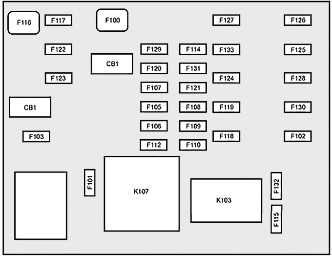
Diagram of the fuse box

Fuse assignment under the hood
Leave a Reply Cancel reply
You must be logged in to post a comment.
Related News

Dodge RAM 100, 150, 250, 350 (1981-1993) – fuse box

Dodge RAM 1500, 2500, 3500 (1994-2001) – fuse box

Dodge RAM 1500, 2500, 3500 (2002-2005) – fuse box

Dodge RAM 1500, 2500, 3500 (2006-2009) – fuse box
2011-2019 Dodge Journey fuse box diagram
The first-generation Dodge Journey after a facelift, available from 2011 to the present. Here you will find fuse box diagrams of Dodge Journey 2011, 2012, 2013, 2014, 2015, 2016, 2107, 2018, and 2019, get information about the location of the fuse panels inside the car, and learn about the function of each fuse.
Table of Contents
Power distribution center.

Interior Fuses

Tom Smith is a passionate car mechanic and automotive enthusiast, specializing in the intricate world of car fuse boxes. With years of hands-on experience under the hood, he has earned a reputation as a reliable expert in his field. As the founder and content creator of the popular blog website 'carsfuse.com,' Tom has dedicated himself to sharing his extensive knowledge of car fuse boxes and electrical systems with the world.
- 2004-2007 KIA Picanto (SA) fuse box diagram
- 2007-2010 KIA Optima / K5 (MG) fuse box diagram
- 2000-2005 KIA Optima/K5 (MS) fuse box diagram
- 2013-2017 KIA Cee’d (JD) fuse box diagram
Leave a comment Cancel reply
Save my name, email, and website in this browser for the next time I comment.

Join our Car Network Ownery > >
Dodge Journey fuse box location and diagrams
It`s time to replace the defective fuse on the Dodge Journey, but you don't know where it is located? Check out the fuse box diagrams for Dodge Journey of different years to protect the wiring system from short circuits.
Learn about the fuse panels and what each fuse layout does for your specific Dodge Journey. Review the diagrams attentively and become a fuse box pro!
Custom-fit Add-ons
Fuse pullers, circuit testers, electric contact spray cleaners, fuses for dodge journey years, 2018 dodge journey, 2014-2017 dodge journey, 2011 dodge journey, 2010 dodge journey, 2009 dodge journey, how to change fuses on your dodge journey.
The fuses in your Dodge Journey are responsible for controlling various electrical systems, such as the headlights, brake lights, horn, power windows, radio, and other accessories. Each electrical circuit has its own fuse, which is typically labeled on the fuse box cover or in the owner's manual.
If a fuse blows, it will cause the corresponding electrical system to stop working. This is a sign that the fuse needs to be replaced. It's important to replace the blown fuse with one that has the same amperage rating as the original fuse. Using a fuse with a higher amperage rating could cause damage to the electrical system or even start a fire.
To change a fuse in your Dodge Journey, follow these steps:
- Locate the fuse box: The fuse box is usually located under the dashboard on the driver's side, or in the engine compartment.
- Identify the blown fuse : Look for the fuse that corresponds to the electrical system that is not working.
- Remove the blown fuse: Use a fuse puller or a pair of pliers to remove the blown fuse.
- Check the amperage rating: Check the amperage rating on the blown fuse to ensure that you use the correct replacement.
- Install the new fuse: Insert the new fuse into the appropriate slot in the fuse box. Make sure it is seated properly.
- Test the electrical system: Turn on the electrical system that was not working to make sure that it is now working properly.
- It's a good idea to keep a few spare fuses in your car so that you can replace them quickly if one blows while you are on the road.
- If the fuses in your car haven't been changed in a while, you may notice when you try to take them out that it's not that easy to do. Over time, the fuses can become stuck in their seats. This can lead to poor contact and, as a result, make it difficult for your electrical system to work. If you notice a strange buildup or damage on the fuse, fill the seat with contact cleaner before installing a new one in that location. Then wait about 15 minutes for the spray to react, blow out the application with compressed air, and then you can install the new fuse in place.

Nilight 372 PCS Car Fuses Assortment Kit...
- 4 Types of Blade Fuses: This assortment kit covers Standard, Mini, Low Profile Mini, and Micro2 Fuses, they are commonly used in most of vehicles such as Cars, Trucks, SUVs, ATVs, UTVs, Campers, RVs, Motorcycles,...

JOREST 120Pcs Car Fuse Kit - Replacement...
- 【High cost-effective fuse kit】-- The kit includes 120pcs standard size fuses and a fuse puller. The car fuses have 11 current specifications (2A /3A / 5A/ 7.5A/ 10A/ 15A/ 20A/ 25A/ 30A/ 35A/40A).
- 【Reasonable quantity...

150pcs Car Automotive Rv Standard Fuses ...
- All Sizes You Need - Covers 10 commonly standard car fuses: 2A/ 3A/ 5A/ 7.5A/ 10A/ 15A/ 20A/ 25A/ 30A/ 35A (15PCS of each model ), fuse puler included.
- Excellent Quality - Riseuvo automotive fuses...

CrocSee 250 Pieces - Car Fuses Assortmen...
- The blade fuses are clearly marked with amperage and color coded for easy identification
- Available in amperage ratings of 2A to 40A (rated at 32 volts), you could always find one that fits your auto

CrocSee 30 Pieces Car Fuses Assortment K...
- Each fuse is clearly marked with amperage and color coded for easy identification
- Available in 20-60 amps, the cartridge fuse is to meet a wide variety of applications
- Includes both standard size (rated at 32...

weideer 22 Values 360pcs Fast Blow Glass...
- weideer top Quality Fast blow Glass Fuses Assortment Kit.
- Fuse Dimension:5x20mm/0.2x0.78in,6x30mm/0.23x1.18in
- Fuse Voltage: 250V
- Fuse Model:6x30mm/10 kinds:0.5A 1A 2A 3A 5A 6A 8A 10A 15A 20A,5x20mm/12 kinds:0.2A 0.5A 1A 2A 3A 4A 5A 8A 10A...

8 Pieces Blade Glass Fuse Puller Inserti...
- PACKAGE INCLUDED - You will receive 4 types of car fuse insertion and removal tools, 2 each, to meet your daily fuse replacement needs. Tools of different specifications do the work of extracting fuses easily...

Komitasui Relay Puller Pliers, Car Fuse ...
- ➤[Applicable]: Universal Puller Pliers for removing electrical relays and Fuse on vehicles.Also work on many heavy duty and industrial applications,Thin tips and offset handles allow for easier use than traditional pliers.
- ➤[Features]: Specially designed tip are...

Baomain Car Automobile Fuse Puller Extra...
- For easy and safe removal of car fuses
- Package Content: 5 x Fuse puller

Jonard Tools FP-600, Fuse Puller with Cu...
- HIGH DURABILITY: Made of heat treated chrome vanadium steel for maximum strength and durability
- VERSATILE USE: Ideal for installing and extracting fuses from line amplifiers and other cylindrical shaped components including heat coils
- SAFE OPERATION:...

VANTRONIK Fuse Puller Relay Puller For F...
- Products: 6.5” Length automotive fuse puller tool, relay puller tool, with serrated teeth and notch, rounded grooves, thin flat-nose duckbill pliers. To be used for the narrow spaces in Car Boat Truck SUV or other...

Gardner Bender FPE-20T Fuse Puller and C...
- Tough insulated plastic fuse puller
- Built-in continuity tester
- LED glows green when fuse is functional
- Made of non-conductive high-grade plastic
- Fits Fuses: 0 to 200A or 0 to 100A/600V
- Safely remove 3/8" to 1-1/8" diameter,...

Digital Multimeter Electrical Test Kit, ...
- Digital Multimeter measures up to 600V AC/DC voltage, 10A DC current and 2 ohm resistance
- Meter also test batteries, diodes, and continuity
- Voltage Tester NCVT-3P has dual-range capabilities to detect from 12 to 1000 V...

AstroAI Multimeter 2000 Counts Digital M...
- VERSATILE DIGITAL MULTIMETER - Accurately measures AC/DC Voltage, DC Current, Resistance, and Diode. This Multimeter is a really useful tool for solving industrial and household electrical issues. Suitable for Household Outlets, Fuses, Batteries (including Vehicles), Automotive...

Crenova MS8233D Auto-Ranging Digital Mul...
- 【100% Safety Assurance】Built-in Double Fuse. Overload Protection on all ranges.
- 【Auto-ranging Tester】Accurately measure AC/DC voltage, AC/DC current, resistance, frequency, continuity, diode, etc.
- 【Backlight Display】 Designed with 3 1/2 digit LCD display and 'Backlight', showing the...

Digital Multimeter AC DC Voltmeter Ohm V...
- Wide Range of Applications: can measure AC and DC voltage, resistance, and current, It can also test circuit continuity, battery quality, and diode biases; a must have addition to all your electrical and electronic tools...

Digital Multimeter DC AC Voltmeter Ohm V...
- Wide Range of Applications: can measure AC and DC voltage, resistance, and current; can test circuit continuity, battery quality, and diode biases; a must-have addition to all your electrical and electronic tools for industrial and...

Klein Tools MM400 Multimeter, Digital Au...
- Multimeter measures up to 600V AC/DC voltage, 10A AC/DC current and 40 MOhms resistance
- Electrical tester measures temperature, capacitance, frequency, duty-cycle, and test diodes and continuity
- CAT III 600V safety rating
- Built to withstand a...

Klein Tools RT250 GFCI Outlet Tester wit...
- LARGE CLEAR LCD READOUT on receptacle tester to instantly view results without the need to look at a chart to understand results
- TEST GFCI TRIP TIME IN SECONDS to find out if the trip breaker...

Sperry Instruments STK001 Non-Contact Vo...
- VERIFIES VOLTAGE PRESENSE: Verifies the presence of AC Voltage prior to working on electrical installation or troubleshooting (GFI6302 and VD6504)
- DURABLE: Hi-Impact Resistant ABS housing with soft over-molded rubber grips with a compact ergonomic design...

Klein Tools ET310 AC Circuit Breaker Fin...
- This circuit breaker finder can quickly and accurately locate the correct circuit breaker in a panel corresponding to the circuit to which an electrical outlet or fixture is connected
- GFCI tester consists of two parts:...

Klein Tools NCVT1P Voltage Tester, Non-C...
- NON-CONTACT DETECTION of AC voltage in cables, cords, circuit breakers, lighting fixtures, switches, non-tamper-resistant outlets, and wires
- VISUAL AND AUDIBLE INDICATORS of voltage detection with a high intensity, bright red LED, and an audible tone

Klein Tools NCVT2PKIT Non-Contact Voltag...
- Kit contains+B2:H150 a non-contact voltage tester and receptacle tester
- Dual range NCVT-2P automatically detects and indicates low voltage range and standard voltage (48-1000V AC)
- NCVT-2P provides non-contact detection of standard voltage in cables, cords, circuit...

Klein Tools RT210 Outlet Tester, Recepta...
- GFCI Tester detects the most common wiring problems in standard and GFCI receptacles
- Works on GFCI outlets and confirms operation of the ground fault protective device
- Built to withstand a 6.6-foot (2m) drop
- Operating temp:...

BW-100 Non-Flammable Electronic Contact ...
- Improves conductivity by blasting away dust and cleaning sensitive electrical equipment
- Non-flammable, quick evaporation, and zero residue
- Prevent contact failure by regularly cleaning
- Safe to use on rubber, metal, and most plastics. Compatibility test on...
![WD-40 Specialist Contact Cleaner Spray, 11 oz. [6-PACK]](https://m.media-amazon.com/images/I/51L0+5m6EwL._AC_QL90_UL90_.jpg?ezimgfmt=0 "2014 journey fuse box location")
WD-40 Specialist Contact Cleaner Spray, ...
- WD-40 Specialist Contact Cleaner is ideal for removing oil, dirt, flux residue, and condensation from sensitive electrical equipment. This quick drying, residue-free formula is safe on metal and plastic
- Cleans sensitive electric equipment. Quick drying....

CRC QD Contact Cleaner, 11 Wt Oz, Indust...
- CRC INDUSTRIES: A market leader that offers impeccably designed chemical solutions to maintain, protect and repair different marine, heavy-duty motor vehicles, industrial-grade engines, household tools and electrical equipment
- QD Contact Cleaner: Helps to effectively eliminate...

Hosa D5S-6 CAIG DeoxIT 5% Spray Contact ...
- Cleans, protects, lubricates, and improves conductivity
- Reduces intermittent connections, arcing, and RFI as well as wear and abrasion
- Safe for use on all metal connectors and contacts and will not harm plastics
- Dispensing Type: Spray

AP Exhaust M200 Exhaust Clamp

Dodge Journey specs Compare
Performance, maintenance.
Forgive our ad-diction! It's just our funky little way of keeping the lights on. Bear with us!
Dodge Journey fuse box and relays diagrams
Explore interactive fuse box and relay diagrams for the Dodge Journey. Fuse boxes change across years, pick the year of your vehicle:

Fuse box diagrams 2020 Journey

Fuse box diagrams 2019 Journey

Fuse box diagrams 2018 Journey

Fuse box diagrams 2017 Journey

Fuse box diagrams 2016 Journey

Fuse box diagrams 2015 Journey

Fuse box diagrams 2014 Journey

Fuse box diagrams 2013 Journey

Fuse box diagrams 2012 Journey

Fuse box diagrams 2011 Journey

Fuse box diagrams 2010 Journey

Fuse box diagrams 2009 Journey

Dodge Journey Electrical Fuse Replacement Guide How to change a blown electrical fuse in a first generation 2009 to 2014 Dodge Journey SUV with pictures.
Copyright 2024 � PaulsTravelPictures.com All Rights Reserved �
Privacy Policy About Paul & Author Contact Info

- [ 7 August 2022 ] Chevy G30 (1988 – 1992) – fuse box diagram Chevy
- [ 7 August 2022 ] Chevy G20 (1988 – 1992) – fuse box diagram Chevy
- [ 5 August 2022 ] GMC Vandura (1988 – 1992) – fuse box diagram Bez kategorii
- [ 31 July 2022 ] Infiniti Q45 (2002 – 2006) – fuse box diagram Infiniti
- [ 26 July 2022 ] Infiniti Q45 (1997 – 2001) – fuse box diagram Infiniti
Dodge Journey (2014 – 2017) – fuse box diagram
8 July 2018 admin Dodge , Journey 0
Year of production: 2014, 2015, 2016, 2017
Power outlet fuses

Interior Fuses
The interior fuse panel is located on the passenger side under the instrument panel.
Underhood Fuses (Power Distribution Center)
The power distribution center is located in the engine compartment.
WARNING: Terminal and harness assignments for individual connectors will vary depending on vehicle equipment level, model, and market.
- Electrical Distribution
Related Articles

Buick Roadmaster (1995) – fuse box diagram
Buick Roadmaster (1995) – fuse box diagram Year of production: 1995 Instrument Panel Fuse Block Fuse Usage 7 Not Used 8 Rear Window Wiper 9 Radio 10 Windshield Wiper/Washer Switch 11 Rear Defog Relay, Air […]
Kubota Tractor M6040 – fuse box diagram
Kubota Tractor M6040 – fuse box diagram Year of production: Fuse box Number Ampere ratting [A] Protected circuit 1 5 Starter Relay 2 15 Auxiliary Power/Air Suspension Seat (if equipped) 3 15 Work Light (Front, […]
Honda Accord (2004) – fuse box diagram
Honda Accord (2004) – fuse box diagram Year of production: 2004 Fuse block (Engine compartment) Number Ampere rating [A] Circuits Protected 1 10 Left Headlight Low 2 (30) (Rear Defroster Coil) 3 10 Left Headlight […]
Copyright © 2024 | MH Magazine WordPress Theme by MH Themes

- Dodge Manuals
- 2014 JOURNEY
- User manual
Dodge 2014 JOURNEY User Manual
- Owner's manual (652 pages)
- Owner's manual (646 pages)
- Owner's manual (651 pages)
- page of 124 Go / 124
Table of Contents
Introduction/welcome.
- Welcome from Chrysler Group Llc
Controls at a Glance
- Driver Cockpit
- Instrument Cluster
Getting Started
- Panic Alarm
- Remote Start
- Keyless Enter-N-Go
- Vehicle Security Alarm
- Supplemental Restraint System (Srs) - Air Bags
- Child Restraints
- Front Seats
- Heated Seats
- Heated Steering Wheel
- Tilt/Telescoping Steering Column
Operating Your Vehicle
- Engine Break-In Recommendations
- Turn Signal/Wiper/Washer/High Beam Lever
- Headlight Switch
- Speed Control
- Climate Control
- Parkview® Rear Back-Up Camera
- Power Sunroof
- Wind Buffeting
Electronics
- Your Vehicle's Sound System
- Identifying Your Radio
- Uconnect® 4.3 & 4.3S at a GLANCE
- Uconnect® 8.4 & 8.4N at a GLANCE
- Siriusxm SATELLITE RADIO
- Ipod®/CD/Aux CONTROLS
- Garmin® Navigation
- Siriusxm TRAVEL LINK
- PLAYING Ipod®/Usb/Mp3 DEVICES
- Uconnect® PHONE
- Uconnect® VOICE COMMAND (8.4 & 8.4N ONLY)
- Video Entertainment System (Ves™)
- Steering Wheel Audio Controls
- Electronic Vehicle Information Center (Evic)
- Programmable Features
- UNIVERSAL GARAGE DOOR OPENER (Homelink®)
- Power Inverter
- Power Outlets
- Trailer Towing Weights (Maximum Trailer Weight Ratings)
- Recreational Towing (Behind Motorhome, Etc.)
What to Do in Emergencies
- Roadside Assistance
- Instrument Cluster Warning Lights
- Indicator Light
- If Your Engine Overheats
- Spare Tire Stowage
- Jacking Instructions
- Road Tire Installation
- Jump-Starting
- Shift Lever Override
- Towing a Disabled Vehicle
- Freeing a Stuck Vehicle
- Event Data Recorder (Edr)
Maintaining Your Vehicle
- Opening the Hood
- Engine Compartment
- Fluids and Capacities
- Maintenance Schedule
- Maintenance Record
- Tire Pressures
- Wheel and Wheel Trim Care
- Exterior Bulbs
Consumer Assistance
- Chrysler Group Llc Customer Center
- Customer Center
- Assistance for the Hearing Impaired
- Publications Ordering
- Reporting Safety Defects in the United States
- Mopar® Accessories
- Authentic Accessories by Mopar
- Frequently Asked Questions
- Driving and Alcohol
Advertisement
Quick Links
- 1 Instrument Cluster
- 2 Fluids and Capacities
- 3 Maintenance Schedule
- Download this manual
Related Manuals for Dodge 2014 JOURNEY

Summary of Contents for Dodge 2014 JOURNEY
- Page 1 > 2014 JOURNEY // USER GUIDE...
- Page 2 > IMPORTANT This User Guide is intended to familiarize you with the important features of your vehicle. The DVD enclosed contains your Owner’s Manual, Navigation/Uconnect Manuals, Warranty ® Booklets, Tire Warranty and Roadside Assistance (new vehicles purchased in the U.S.) or Roadside Assistance (new vehicles purchased in Canada) in electronic format.
Page 3: Table Of Contents
Page 4: introduction/welcome.
- Page 5 If your symptoms persist, please see an authorized dealer. CHRYSLER, DODGE, JEEP, RAM TRUCK, SRT, ATF+4, MOPAR and Uconnect are registered trademarks of Chrysler Group LLC.
Page 6: Controls At A Glance
- Page 7 CONTROLS AT A GLANCE 10. Climate Controls pg. 33 11. Power Outlet pg. 70 12. Shifter 13. Emergency Brake Pedal 14. Opening The Hood pg. 93 15. Power Door Locks 16. Power Windows 17. Power Mirror Switch...
Page 8: Instrument Cluster
- Page 9 CONTROLS AT A GLANCE 4. Fuel Gauge 5. Speedometer 6. Fuel Filler Door Location Indicators - Turn Signal Indicators - High Beam Indicator - Front Fog Light Indicator - Vehicle Security Indicator* - Electronic Stability Control (ESC) Off Indicator - Electronic Speed Control ON Indicator - Electronic Speed Control SET Indicator * If equipped ** Bulb Check with Key On...
Page 10: Getting Started
Page 11: remote start.
- Page 12 GETTING STARTED • DO NOT grab the door handle, when pressing the door handle lock button. This could unlock the door(s). Press The Button To Lock Do NOT Grab The Handle When Locking NOTE: • If “Unlock All Doors 1st Press” is programmed all doors will unlock when you grab hold of the front driver's door handle.
- Page 13 GETTING STARTED Lock Or Unlock The Liftgate: • With a valid Keyless Enter-N-Go™ Key Fob within 3 feet (1 meter) of the liftgate, press the electronic liftgate lock/unlock pad located to the left of the liftgate handle to unlock the liftgate. Press the button a second time to lock the liftgate.
- Page 14 GETTING STARTED Stopping • Place the shift lever in PARK. • Press the ENGINE START/STOP button once. The ignition switch will return to the OFF position. • If the shift lever is not in PARK, the ENGINE START/STOP button must be held for two seconds and vehicle speed must be above 5 mph (8 km/h) before the engine will shut off.
Page 15: Vehicle Security Alarm
Page 16: supplemental restraint system (srs) - air bags, page 17: child restraints.
- Page 18 GETTING STARTED LATCH — Lower Anchors And Tethers For CHildren • Your vehicle is equipped with the child restraint anchorage system called LATCH, which stands for Lower Anchors and Tethers for CHildren. • The second row seating positions have lower anchors and top tether anchors. The third row seating positions (if equipped) do not have lower anchors or top tether anchors.
- Page 19 GETTING STARTED • The center seating position in this vehicle has a single dedicated anchorage. Use anchorages B and C to install a child seat in the center position. Do not use anchorages C and D to install a child seat. If you are installing three child restraints, you must use the seatbelt to install the center child restraint.
- Page 20 GETTING STARTED Installing The Child Restraints Using The Vehicle Seat Belts • The seat belts in the outboard passenger seating positions are equipped with a Switch- able Automatic Locking Retractor (ALR). The center seating positions are equipped with a cinching latch plate. Both types of seat belts are designed to keep the lap portion of the seat belt tight around the child restraint.
- Page 21 GETTING STARTED Installing The Top Tether Strap (With Either Lower Anchors Or Vehicle Seat Belt): When installing a forward-facing child restraint, always secure the top tether strap, up to the tether anchor weight limit, whether the child restraint is installed with the lower anchors or the vehicle seat belt.
- Page 22 GETTING STARTED 3. Lift the seat cushion up and push back to lock it in the booster seat position. 4. Place the child upright in the seat with their back firmly against the seatback. 5. Grasp the latch plate and pull out the seat belt.
Page 23: Front Seats
- Page 24 GETTING STARTED Fold-Flat Front Passenger Seat • The front passenger seat can be folded flat to allow for extended cargo space. Pull up on the recliner lever to fold down the seatback. Flip 'n Stow™ Front Passenger Seat Storage • The seat latch release-loop is located in the center of the seat cushion between the seat cushion and the seatback.
Page 25: Rear Seats
- Page 26 GETTING STARTED STADIUM Tip ’n Slide™ (EASY ENTRY/EXIT SEAT) — SEVEN PASSENGER MODELS To Move The Second-Row Passenger Seat Forward NOTE: Raise the 20% seatback/armrest before moving the 60% seat to allow for full seat travel. • To allow passengers to easily enter or exit the third-row passenger seats move the Tip ’n Slide™...
Page 27: Heated Seats
Page 28: heated steering wheel, page 29: tilt/telescoping steering column, page 30: operating your vehicle, page 31: headlight switch, page 32: speed control.
- Page 33 OPERATING YOUR VEHICLE Accel/Decel To Increase Speed • When the Electronic Speed Control is set, you can increase speed by pushing the RES + button. The speed increment shown is dependant on the speed of U.S. (mph) or Metric (km/h) units: U.S.
- Page 34 OPERATING YOUR VEHICLE Metric Speed (km/h) • Pressing the SET - button once will result in a 2 km/h decrease in set speed. Each subsequent tap of the button results in a decrease of 2 km/h. • If the button is continually pressed, the set speed will continue to decrease until the button is released, then the new set speed will be established.
Page 35: Climate Control
- Page 36 OPERATING YOUR VEHICLE Uconnect® 8.4 Automatic Climate Controls Climate Control Knobs • For your convenience the climate controls can be operated by using the soft-keys located on the touch screen or the climate control knobs below the Uconnect® display.
Page 37: Parkview® Rear Back-Up Camera
Page 38: power sunroof, page 39: wind buffeting, page 40: electronics.
- Page 41 ELECTRONICS 7. Tune/Scroll Knob/Browse/Enter Button 8. SD Card Slot (push in to insert/eject) pg. 55 9. Front Power Outlet pg. 70 10. CD Slot 11. CD Eject Button 12. Audio Jack/USB Port pg. 54...
Page 42: Identifying Your Radio
Page 43: uconnect® 4.3 & 4.3s at a glance, page 44: uconnect® 8.4 & 8.4n at a glance.
- Page 45 ELECTRONICS Setting The Time • Model 8.4N synchronizes time automatically via GPS, so should not require any time adjustment. If you do need to set the time manually, follow the instructions below for Model 8.4. • For Model 8.4, turn the unit on, then touch the “Time Display” at the top of the screen. Touch “Yes”.
Page 46: Radio
Page 47: siriusxm satellite radio.
- Page 48 ELECTRONICS Selecting SiriusXM Satellite Channels Seek Up/Seek Down • Touch the “Seek arrow” soft-keys for less than two seconds to seek through channels in SAT mode. • Touch and hold either “arrow” soft-key for more than two seconds to bypass channels without stopping.
- Page 49 ELECTRONICS Browse • Lets you browse the SiriusXM Satellite Radio channel listing, Favorites, Genres, Game Zone, and Weather channels. Jump setting, and also provides the SiriusXM Satellite Radio channel list. Browse contains many sub-menus. Browse Sub-Menu Description Sub-Menu Shows the channel listing. Genre Provides a list of all genres, and lets you jump to a channel within the selected genre.
Page 50: Ipod®/Cd/Aux Controls
- Page 51 ELECTRONICS Models 8.4 & 8.4N • The iPod®/USB, CD, Audio Jack, SD Card or Bluetooth® source is accessed by touching the “Player” soft-key to enter the Player main screen, then touch the “Source” soft-key and choose between Disc, Aux, iPod®, Bluetooth® or SD Card. NOTE: Uconnect®...
Page 52: Garmin® Navigation
- Page 53 ELECTRONICS • Dead Reckoning technology uses the speed sensors attached to your vehicle’s drivetrain, and a gyroscope, to supplement the existing GPS data. The combined data provides accurate positioning for your vehicle in tunnels, indoor parking garages, urban canyons, and any other area where GPS signals can become obstructed. Finding Points Of Interest •...
- Page 54 ELECTRONICS Following Your Route • Your route is marked with a magenta line on the map. If you depart from the original route, your route is recalculated. A speed limit icon could appear as you travel on major roadways. • Lane Assist helps you decide which lane to be in at upcoming junctions. •...
Page 55: Siriusxm Travel Link
Page 56: playing ipod®/usb/mp3 devices, page 57: uconnect® phone.
- Page 58 ELECTRONICS Start Pairing Procedure On The Radio • Models 8.4, 8.4N: Touch the “Phone” soft-key and then the “Settings” soft-key. Next, touch “Add Device.” • Models 4.3, 4.3S: Press the MORE hard-key, then touch the “Phone” soft-key. Next, touch the “Settings” soft-key and then “Add Device.” •...
- Page 59 ELECTRONICS Select The Mobile Phone's Priority Level • When the pairing process has successfully completed, the system will prompt you to choose whether or not this is your favorite phone. Selecting Yes will make this phone the highest priority. This phone will take precedence over other paired phones within range. Only one phone can connected at a time.
- Page 60 ELECTRONICS Phone Menu Screen — Models 8.4 & 8.4N Making A Phone Call • Press the Uconnect® Phone button • After the BEEP, say “dial” then the number (or “call” then the name as listed in your phone; see Phonebook). NOTE: You can also initiate a call by using the touchscreen on the Phone main screen.
- Page 61 ELECTRONICS Common Phone Commands (Examples) • “Call John Smith” • “Call John Smith mobile” • “Dial 1 248 555 1212” • “Call Emergency” • “Call Towing Assistance” • “Redial” Phonebook • Uconnect® radios will automatically download your phonebook from your paired phone, if this feature is supported by your phone.
Page 62: Uconnect® Voice Command (8.4 & 8.4N Only)
- Page 63 ELECTRONICS Changing The Volume • Start a dialogue by pressing the Voice Command button , then say a command (for example, “help”). • Use the radio ON/OFF VOLUME rotary knob to adjust the volume to a comfortable level while the Voice Command system is speaking. The volume setting for Voice Command is different than the audio system.
- Page 64 ELECTRONICS Common Navigation Voice Commands • To access the navigation voice commands, press the Uconnect® Voice Command button while in any mode and say “Navigation.” • Once in the Navigation feature, you can simply Say What You See on the touchscreen to give a navigation voice command.
Page 65: Video Entertainment System (Ves™)
Page 66: steering wheel audio controls, page 67: programmable features, page 68: universal garage door opener (homelink®).
- Page 69 ELECTRONICS NOTE: Erasing all channels should only be performed when programming HomeLink® for the first time. Do not erase channels when programming additional buttons. If you have any problems, or require assistance, please call toll-free 1-800-355-3515 or, on the Internet at www.HomeLink.com for information or assistance. Programming A Rolling Code NOTE: For programming Garage Door Openers that were manufactured after 1995.
- Page 70 ELECTRONICS Programming A Non-Rolling Code NOTE: For programming Garage Door Openers manufactured before 1995. 1. Turn the ignition switch to the ON/RUN position. 2. Place the hand-held transmitter 1 to 3 inches (3 to 8 cm) away from the HomeLink® button you wish to program while keeping the HomeLink®...
Page 71: Power Inverter
Page 72: power outlets, page 73: utility, page 74: recreational towing (behind motorhome, etc.), page 75: what to do in emergencies.
- Page 76 WHAT TO DO IN EMERGENCIES - Air Bag Warning Light This light will turn on for four to eight seconds as a bulb check when the ignition switch is first turned to the ON/RUN position. If the light is either not on during starting, stays on, or turns on while driving, have the system inspected at an authorized dealer as soon as possible.
- Page 77 WHAT TO DO IN EMERGENCIES Please note that the TPMS is not a substitute for proper tire maintenance, and it is the driver’s responsibility to maintain correct tire pressure, even if under-inflation has not reached the level to trigger illumination of the TPMS low EVIC display. Your vehicle has also been equipped with a TPMS malfunction indicator to indicate when the system is not operating properly.
- Page 78 WHAT TO DO IN EMERGENCIES - Seat Belt Reminder Light When the ignition switch is first turned to the ON/RUN position, this light will turn on for four to eight seconds as a bulb check. During the bulb check, if the driver's seat belt is unbuckled, a chime will sound.
Page 79: Indicator Light
- Page 80 WHAT TO DO IN EMERGENCIES - High Beam Indicator Indicates that headlights are on high beam. - Front Fog Light Indicator This indicator will illuminate when the front fog lights are on. - Vehicle Security Light This light will flash rapidly for approximately 15 seconds when the vehicle theft alarm is arming.
Page 81: If Your Engine Overheats
Page 82: jacking and tire changing.
- Page 83 WHAT TO DO IN EMERGENCIES 5. Turn OFF the ignition. 6. Block both the front and rear of the wheel diagonally opposite of the jacking position. For example, if changing the right front tire, block the left rear wheel. NOTE: Passengers should not remain in the vehicle when the vehicle is being jacked.
Page 84: Spare Tire Stowage
- Page 85 WHAT TO DO IN EMERGENCIES 3. Place the jack underneath the lift area that is closest to the flat tire. Turn the jack screw clockwise to firmly engage the jack saddle with the lift area of the sill flange. 4. Raise the vehicle by turning the jack screw clockwise with the jack handle. Raise the vehicle until the tire just clears the road surface and enough clearance is obtained to install the spare tire.
Page 86: Road Tire Installation
- Page 87 WHAT TO DO IN EMERGENCIES Vehicles Without Wheel Covers 1. Mount the road tire on the axle. 2. Install the remaining lug nuts with the cone shaped end of the nut toward the wheel. Lightly tighten the lug nuts. 3. Lower the vehicle to the ground by turning the jack handle counterclockwise. 4.
- Page 88 WHAT TO DO IN EMERGENCIES WARNING! • Do not attempt to change a tire on the side of the vehicle close to moving traffic. Pull far enough off the road to avoid the danger of being hit when operating the jack or changing the wheel.
Page 89: Jump-Starting
- Page 90 WHAT TO DO IN EMERGENCIES 4. Connect the opposite end of the negative (-) jumper cable to the remote negative (-) post of the vehicle with the discharged battery. 5. Start the engine in the vehicle that has the booster battery, let the engine idle a few minutes, and then start the engine in the vehicle with the discharged battery.
Page 91: Shift Lever Override
Page 92: towing a disabled vehicle, page 93: freeing a stuck vehicle, page 94: event data recorder (edr), page 95: maintaining your vehicle, page 96: engine compartment.
- Page 97 MAINTAINING YOUR VEHICLE...
Page 98: Fluids And Capacities
- Page 99 MAINTAINING YOUR VEHICLE Component Fluid, Lubricant, or Capacities Genuine Part Only use MOPAR® ATF+4® Automatic Transmission Fluid. Failure to use ATF+4® Automatic Transmission — fluid may affect the function or performance of your transmission. We recommend you use MOPAR® DOT 3 and SAE Brake Master Cylinder J1703.
Page 100: Maintenance Schedule
- Page 101 MAINTAINING YOUR VEHICLE Severe Duty All Models Change Engine Oil at 4000 miles (6,500 km) if the vehicle is operated in a dusty and off road environment. This type of vehicle use is considered Severe Duty. Once A Month Or Before A Long Trip: •...
- Page 102 MAINTAINING YOUR VEHICLE...
- Page 103 MAINTAINING YOUR VEHICLE...
Page 104: Maintenance Record
Page 105: fuses.
- Page 106 MAINTAINING YOUR VEHICLE Underhood Fuses • The power distribution center is located in the engine compartment. Cavity Cartridge Fuse Mini-Fuse Description Interior Power Distribution F101 60 Amp Yellow Center Rail Interior Power Distribution F102 60 Amp Yellow Center Rail Interior Power Distribution F103 60 Amp Yellow Center Rail...
Page 107: Tire Pressures
Page 108: wheel and wheel trim care, page 109: exterior bulbs, page 110: consumer assistance, page 111: reporting safety defects in the united states, page 112: mopar® accessories, page 113: frequently asked questions, page 114: index.
- Page 115 INDEX EVIC Display ....6 Jack Operation ... .80, 82 Exterior Lights ....107 Jump Starting .
- Page 116 INDEX Outlet Heated ....25 Power ....70 Manual ....21 Overheating, Engine .
- Page 117 INDEX Uconnect® Voice Command ..60 Washer Underhood Fuses ... .104 Rear ....29 Universal Garage Door Opener Washers, Windshield .
- Page 118 NOTES...
- Page 119 NOTES...
- Page 120 NOTES...
- Page 121 NOTES...
- Page 122 NOTES...
Page 123: Driving And Alcohol
- Page 124 DOWNLOAD A FREE ELECTRONIC COPY OF THE OWNER’S MANUAL OR WARRANTY BOOKLET by visiting the Owners tab at: www.dodge.com (U.S.) www.dodge.ca (Canada) 14JC49-926-AA Fourth Edition REV 1 JOURNEY User Guide...
Rename the bookmark
Delete bookmark, delete from my manuals, upload manual.
You are here
Fuses and relays dodge journey (jc; 2007 - 2010), in the engine compartment.
The Dodge Journey is a crossover SUV produced by FCA US LLC since 2008. It was introduced in 2007 at the Frankfurt Motor Show. Originally planned for the US market. In this material, we will analyze in detail the Dodge Jorney fuse diagrams (factory index JC ) of the 1st generation 2007, 2008, 2009, 2010 of release.


Fuse Box Diagrams
All automotive fuse box diagrams in one place
Dodge Journey (2009-2010) fuses and relays
Ad vertisements
In this article, we consider the first-generation Dodge Journey before a facelift, which was produced from 2009 to 2010. Here you will find fuse box diagrams of Dodge Journey 2009 and 2010 , get information about the location of the fuse panels inside the car, and learn about the assignment of each fuse (fuse layout).
See other Dodge Journey:

Fuse Layout Dodge Journey 2009-2010

Cigar lighter / power outlet fuses in the Dodge Journey are the fuses M6, M7 and M36 in the engine compartment fuse box.
Table of Contents
Fuse box location

Fuse box diagram

Learn more:
IMAGES
VIDEO
COMMENTS
Fuse box diagram (location and assignment of electrical fuses) for Dodge Journey (2011, 2012, 2013, 2014, 2015, 2016, 2107, 2018, 2019).
50. Cabin Heater #3 - If Equipped. F184. 30. Front Wiper Motor. WARNING: Terminal and harness assignments for individual connectors will vary depending on vehicle equipment level, model, and market. Dodge, Journey electricity. Dodge Journey (2014 - 2017) - fuse box diagram.
Dodge Journey 2014 Fuse Box. Dodge Hits: 2091. Dodge Journey 2014 Fuse Box Info. Passenger fuse box location: The interior fuse box is located on the passenger side under the glove box. Engine compartment fuse box: Fuse Box Diagram | Layout. Passenger compartment fuse box: Fuse/Relay N°.
Short video on the location of all fuse boxes / junction boxes (TIPM) on Dodge Journey SUV ( 2011 | 2012 | 2013 | 2014 | 2015 | 2016 | 2017 | 2018 | 2019 | 2...
Buy YOUCANIC Pro Scanner https://www.youcanic.com/scanner/Get Factory Service Repair Manuals & Specs https://www.youcanic.com/manualsAsk Car Questions & Get ...
Dodge Journey (2014 - 2017) Fuse Box Diagram. Jonathan Yarden Oct 22, 2021 · 5 min. read. In this article you will find a description of fuses and relays Dodge, with photos of block diagrams and their locations. Highlighted the cigarette lighter fuse (as the most popular thing people look for). Get tips on blown fuses, replacing a fuse, and more.
2014 Dodge Journey fuse box diagram. This Journey has 2 different fuse boxes: Interior Fuses diagram. Underhood Fuses (Power Distribution Center) diagram. Type Description; Fuse FMM/MCase . 30A: F100. 110V AC Inverter - [If Equipped] Fuse MICRO2 . 10A: F101. Interior Lights. Fuse MICRO2 . 20A: F102.
Fuse box diagrams for Dodge Journey (2011, 2012, 2013, 2014, 2015, 2016, 2017, 2018, 2019, and 2020), including the location of blocks, a list of fuses and relays ...
Dodge Journey (2011-2019) - fuse box diagram Year of manufacture: 2011, 2012, 2013, 2014, 2015, 2016, 2107, 2018 i 2019. Internal fuses Fuse box location The ...
The first-generation Dodge Journey after a facelift, available from 2011 to the present. Here you will find fuse box diagrams of Dodge Journey 2011, 2012, 2013, 2014 ...
See more on our website: https://fuse-box.info/dodge/dodge-journey-2011-2018-fusesFuse box diagram (location and assignment of electrical fuses) for Dodge Jo...
To change a fuse in your Dodge Journey, follow these steps: Locate the fuse box: The fuse box is usually located under the dashboard on the driver's side, or in the engine compartment. Identify the blown. fuse. : Look for the fuse that corresponds to the electrical system that is not working. Remove the blown fuse: Use a.
Dodge Journey fuse box and relays diagrams. ... Fuse box diagrams 2016 Journey. Fuse box diagrams 2015 Journey. Fuse box diagrams 2014 Journey. Fuse box diagrams 2013 Journey. Fuse box diagrams 2012 Journey. Fuse box diagrams 2011 Journey. Fuse box diagrams 2010 Journey. Fuse box diagrams 2009 Journey. Is your car missing? Ask for your diagram.
2014. Fuse Box. DOT.report provides a detailed list of fuse box diagrams, relay information and fuse box location information for the 2014 Dodge Journey AWD. Click on an image to find detailed resources for that fuse box or watch any embedded videos for location information and diagrams for the fuse boxes of your vehicle.
The Dodge Journey is a mid-size SUV produced by FCA US LLC since 2008. The car was presented in 2007 at the Frankfurt Motor Show. Originally planned for the US market, it also became available in other markets as the Fiat Freemont. In this material, we will analyze in detail the 1st generation Dodge Jorney ( JC) fuse diagrams in restyling 2010 ...
FUSE BOX LOCATION ON A 2011 2012 2013 2014 2015 2016 2017 2018 2019 DODGE JOURNEY .PLEASE SUBSCRIBE!!!#DODGE #DODGEJOURNEY #FUSE #FUSEBOX #FUSEBOXLOCATIONDODGE
How to change a blown electrical fuse in a first generation 2009 to 2014 Dodge Journey SUV with pictures. Main Menu Home Digital Cameras. Misc. Pictures ... The interior passenger compartment fuse box is located in the front passenger foot well underneath the glove box. Pull off the retaining clip on the front edge (closest to you) of the fuse ...
Dodge Journey (2014 - 2017) - fuse box diagram Year of production: 2014, 2015, 2016, ... The interior fuse panel is located on the passenger side under the instrument panel. Cavity: Cartridge fuse: Mini fuse: Description: F100: 30: 110V AC Inverter - If Equipped: F101: 10: Interior Lights: F102: 20:
Page 124 DOWNLOAD A FREE ELECTRONIC COPY OF THE OWNER'S MANUAL OR WARRANTY BOOKLET by visiting the Owners tab at: www.dodge.com (U.S.) www.dodge.ca (Canada) 14JC49-926-AA Fourth Edition REV 1 JOURNEY User Guide... View and Download Dodge 2014 JOURNEY user manual online. 2014 JOURNEY automobile pdf manual download.
2014 Dodge Journey Fuse Box Info | Fuses | Location | Diagrams | Layouthttps://fuseboxinfo.com/index.php/cars/25-dodge/1220-dodge-journey-2014-fuses
It is located on the right side behind the protective cover. ... Vehicle Information Center (EVIC) - If Equipped, Interior Lights, Steering Wheel Switches - If Equipped, Switch Box: 15: M21: Automatic Shutdown (ASD) #3: 20: M22: Right horn: 10: M23: Left horn: 10: M24: Rear wiper: 25: M25: Dodge Journey fuel pump fuse; diesel pump; 20: M26 ...
About Press Copyright Contact us Creators Advertise Developers Terms Privacy Policy & Safety How YouTube works Test new features NFL Sunday Ticket Press Copyright ...
In this article, we consider the first-generation Dodge Journey before a facelift, which was produced from 2009 to 2010. Here you will find fuse box diagrams of Dodge Journey 2009 and 2010, get information about the location of the fuse panels inside the car, and learn about the assignment of each fuse (fuse layout). See other Dodge Journey: