
Trane Defrost Control Board LED Codes | Solve Common Issue!
If your Trane furnace is equipped with a defrost control board , you can use the LED codes to help troubleshoot any problems that may arise. The most common code is the “red flash” which indicates that the board is in defrost mode.
Other codes include the “green flash” which means that the furnace is operating normally, and the “amber flash” which indicates a problem with the igniter.

Page Contents
Trane Defrost Control Board LED Codes
The Trane Defrost Control Board is a crucial component of HVAC systems that helps to regulate the defrost cycle, ensuring the efficient functioning of the system. The board is equipped with LED codes that allow troubleshooting and identification of issues that could arise during operation.
The codes and their meanings are as follows:
- Steady Green LED – The system is operating normally.
- Steady Red LED – The defrost control board has detected a fault and is in lockout mode.
- Flashing Red LED – The sensor is not detecting proper temperature, indicating a possible faulty sensor or a wiring issue.
- Flashing Green LED – The system is in defrost mode, and the board is actively monitoring the process.
- Steady On – Power is present
- Flashing Slowly – Normal operation
- Flashing Rapidly – Defrost is active
- Two Flashes – High-pressure switch open
- Three Flashes – Low-pressure switch open
- Four Flashes – Auxiliary limit switch open
- Five Flashes – Outdoor temperature sensor fault
- Six Flashes – Reversing valve fault
- Seven Flashes – Defrost control board fault
Understanding these LED codes is crucial for HVAC technicians to identify and resolve any issues that may arise in the Trane Defrost Control Board.
What are the Codes for a Trane Furnace?
There is no one-size-fits-all answer to this question, as the codes for a Trane furnace will vary depending on the model and year of your furnace. However, you can generally find the code information for your furnace in the owner’s manual or by contacting Trane customer service.
How Do You Test a Trane Defrost Board?
There are a few things that you need to do in order to test a Trane defrost board. The first thing that you will need to do is locate the board. Once you have found the board, you will want to remove it from the unit. Next, you will want to check for any visual damage on the board. If there is any damage, you will want to replace the board. If there is no visual damage, you will then want to connect a multimeter to the board. You will want to set the multimeter to ohms and check for continuity between the two terminals on the board. If there is continuity, then the board is good. However, if there is no continuity, then the board needs to be replaced.

What Causes a Hard Lockout on a Heat Pump?
A hard lockout on a heat pump is caused by a number of different things. The most common cause is when the outdoor temperature drops below the minimum set point for the heat pump. This can be caused by a number of different things, including a cold front moving in, or simply the temperature dropping at night. When this happens, the heat pump will shut off completely in order to prevent damage from happening to the unit. Another common cause of a hard lockout is when the indoor temperature sensor fails. This can cause the heat pump to think that the indoor temperature is too low, even when it isn’t, and as a result, it will shut off. Finally, if there is a problem with the outdoor fan, this can also cause a hard lockout. If the fan isn’t able to turn on, then the heat pump won’t be able to circulate air properly and it will shut down in order to prevent overheating.
What Does Hard Lockout Mean on a Trane Heat Pump?
If your Trane heat pump is locked out, it means that the system has been turned off and can’t be restarted until a qualified technician resets it. This usually happens when the system detects a problem that could cause damage or harm, such as an overheating condition.
Once the problem has been resolved, the lockout can be reset and the heat pump will operate normally again.
Trane 4Twr4 Fault Codes
If you’re a Trane 4TWR4 owner, you know that these units are some of the most reliable and durable on the market. But even the best units can develop faults over time. If your 4TWR4 is displaying a fault code, it’s important to know what that code means so you can take steps to fix the problem. There are four main fault codes that your 4TWR4 may display:
• Code 01: This indicates that there is a problem with the unit’s condenser fan. The most likely cause is a dirty or damaged fan blade. You’ll need to clean or replace the blade to fix this problem.
• Code 02: This indicates that there is a problem with the unit’s evaporator fan. The most likely cause is a dirty or damaged fan blade. You’ll need to clean or replace the blade to fix this problem.
• Code 03: This indicates that there is a problem with the unit’s compressor. The most likely cause is a blown fuse or tripped breaker.
Trane LED Codes
If you have a Trane furnace, you may be wondering what the different LED codes mean. Here is a list of the most common codes and their meanings:
Blinking Green Light: This indicates that the furnace is in standby mode and waiting for a call for heat. Solid Green Light: This means that the furnace is operating normally.
Flashing Red Light : This code indicates that there is an error with the furnace. The specific error will be displayed on the control panel. Consult your owner’s manual for troubleshooting steps.
Continuous Red Light: This means that the limit switch has been activated and the furnace needs to be serviced by a qualified technician.
Trane Furnace Error Codes
Trane furnace error codes are an essential diagnostic tool for identifying issues with your heating system. These codes not only help technicians identify problems quickly but also provide homeowners with the necessary information to troubleshoot issues before calling a professional.
Here are the most common Trane furnace error codes and their meanings:
- 2 flashes: Indicates a problem with the pressure switch.
- 3 flashes: Indicates an issue with the draft inducer motor.
- 4 flashes: Indicates an open limit switch.
- 5 flashes: Indicates a problem with the flame sensor.
- 6 flashes: Indicates an issue with the rollout switch.
- 7 flashes: Indicates a problem with the gas valve.
- 8 flashes: Indicates a problem with Low flame sense signal.
- 9 flashes: Indicates a problem with Igniter.
By familiarizing yourself with these codes, you’ll be better equipped to handle any furnace issues that arise.

Besides the above, you may also find the following error codes for Trane Furnace:
- 126: Internal control fault
- 131: Ignition failure
- 132: Flame sensor failure
- 133: Limit circuit fault
- 147: Low flame signal
- 151: Blower motor fault
- 161: AC power loss
- 164: Open high-limit device
These error codes can help a technician quickly identify the issue and provide a solution, ensuring that your Trane furnace runs smoothly and efficiently.
Trane Troubleshooting Guide
If your Trane unit isn’t working properly, you may be able to troubleshoot and fix the problem yourself. This Trane Troubleshooting Guide will help you identify common issues and provide solutions. First, check the thermostat to make sure it is set correctly. If the thermostat is set too low, the unit won’t run. If the thermostat is set too high, the unit will run continuously without cooling the home. Next, check for power failures. The circuit breaker may have tripped or a fuse may have blown. Reset the breaker or replace the fuse and see if that fixes the problem. If your unit still isn’t running, there could be an issue with the actual unit itself. First, check to see if there is debris blocking the air intake or exhaust vents. If so, remove the debris and try again. Next, check for freezing coils. Ice can build up on the coils and prevent proper airflow. Turn off your unit and let it thaw for several hours before restarting it again. Finally, if all else fails, call a professional for assistance.
Trane Air Handler Blinking Lights
If you have a Trane air handler in your home, you may have noticed that the lights on the unit are blinking. While this may be alarming at first, it’s actually a normal part of the unit’s operation. The blinking lights indicate that the air handler is in standby mode and is waiting for a command from the thermostat. Once the thermostat tells the air handler to start, the lights will stop blinking and the unit will begin heating or cooling your home as needed.
Trane Voyager Error Codes
If you’re getting error codes on your Trane Voyager, it means there’s a problem with the unit. Here are some common error codes and what they mean:
E01 – This indicates that the evaporator temperature is too high. Check to make sure that the coils are clean and that the air filter isn’t clogged.
E02 – This code means that the condenser temperature is too high. Again, check the coils and air filter. Make sure the unit has proper ventilation.
E03 – The third code stands for “freeze protection.” This means that the unit is sensing a potential for freezing temperatures and is shutting down to prevent damage. Check your thermostat settings and make sure the unit is in heating mode. If it still doesn’t work, call a technician. These are just a few of the most common Trane Voyager error codes . If you’re experiencing problems with your unit, don’t hesitate to call a technician or reference your owner’s manual for more information.
Trane Ac Blinking Green Light
If you have a Trane air conditioner , you may have noticed that the green light is blinking. This is normal and indicates that the unit is in standby mode. The green light will blink when the unit is first turned on, and then it will remain lit when the unit is running. If the green light starts blinking again, it means that the unit has been turned off and is in standby mode once again.
Trane Eev Control Board Troubleshooting
If you have a Trane EEV control board that is giving you trouble, there are some things you can do to troubleshoot the problem. First, check all of the connections to make sure they are tight and secure. Next, check the circuit breaker to see if it has tripped. If neither of these solutions solves the problem, you may need to replace the control board.
Heat Pump Defrost Board: Diagnostic Procedures
The Trane Defrost Control Board is responsible for managing the defrost cycle of your Trane AC unit. If there is a problem with the board, it will display an error code on the LED display.
This article lists the codes and what they mean, so you can troubleshoot the issue and get your AC unit up and running again.
Related Articles:
- Mitsubishi Msz-Fh12Na Troubleshooting | Solve Common Issues
- Carrier APU AC Not Working: Identify and Fix the Issue!
- P6 Error Code on Your Air Conditioner
- Trane Ac Unit Fan Not Spinning
My name is Aris, and I am a certified HVAC technician. I have been working in this field for over 5 years and have a lot of experience with different AC units. I write here to help people solve their Air Conditioning problems and find the best solutions for their needs.
If you are having any issues with your air conditioner or are thinking about buying a new one, be sure to check out my blog!
Leave a Reply Cancel reply
Your email address will not be published. Required fields are marked *
Save my name, email, and website in this browser for the next time I comment.
Maintenance – Trane Voyager 1 Rooftop Unit TSD User Manual
- Original mode

Maintenance
RT-SVX20A-E4
Below is the complete listing of failure indication causes:
System failure
Check the voltage between terminals 6 and 9 on J6, it should read approximately 32 VDC. If no voltage is present, a system failure has occurred. Refer to Step 4 in the previous section for the recommended troubleshooting procedure.
Heating Failure
Verify Heat Failure by Ignition Module (IGN) LED indicator:
OFF: No Power or Failure
Slow Flash: Normal, Heat Call
Fast Flash: Error Code: 1 Flash: Communication Failure 2 Flashes:
3 Flashes: Pressure Switch Fail 4 Flashes TC01 or TC02 Open 5 Flashes: Flame w/o Gas Valve 6 Flashes: Flame Rollout Open
Cooling Failure 1. Cooling and heating set point
(slide pot) on the zone sensor has failed. Refer to the "Zone Sensor Test Procedure" section.
2. Zone temperature thermistor
ZTEMP on ZTS failed. Refer to the "Zone Sensor Test Procedure" section.
3. CC1 or CC2 24 VAC control circuit
has opened, check CC1 & CC2 coils, and any of the controls below that apply to the unit (HPC1, HPC2).
4. LPC1 has opened during the
3 minute minimum "on time" during 4 consecutive compressor starts, check LPC1 or LPC2 by testing voltage between the J1-8 & J3-2 terminals on the RTRM and ground. If 24 VAC is present, the LPC's has not tripped. If no voltage is present, LPC's has tripped.
Service Failure 1. If the supply fan proving switch
has closed, the unit will not operate (when connected to RTOM), check the fan motor, belts, and proving switch.
2. Clogged filter switch has closed,
check the filters.
Simultaneous Heat and Cool Failure 1. Emergency Stop is activated
The second method for determining system status is done by checking voltage readings at the RTRM (J6).
The system indication descriptions and the approximate voltages are listed below.
System Failure
Measure the voltage between terminals J6-9 & J6-6.
Normal Operation = approximately 32 VDC
System Failure = less than 1 VDC, approximately 0.75 VDC
Test Mode = voltage alternates between 32 VDC & 0.75 VDC
Heat Failure
Measure the voltage between terminals J6-7 & J6-6.
Heat Operating = approximately 32 VDC
Heat Off = less than 1 VDC, approximately 0.75 VDC
Heating Failure = voltage alternates between 32 VDC & 0.75 VDC
Cool Failure
Measure the voltage between terminals J6-8 & J6-6.
Cool Operating = approximately 32 VDC
Cool Off = less than 1 VDC, approximately 0.75 VDC
Cooling Failure = voltage alternates between 32 VDC & 0.75 VDC
Voyager 1 Rooftop Unit TSH 060
- Canon - AE-1
- Fitbit - Flex
- Nikon - D5000
- Nikon - D40
- Nikon - D3100
- Nikon - D90
- Nikon - D7000
- Nikon - D80
- Nikon - D3000
- HP - Officejet Pro 8600
- Canon - EOS 60D
- HP - 12C Financial calculator

Trane Furnace Error Codes – What They Mean
In this guide, you’ll find a list of the most common Trane furnace error codes, along with what each one means and what you should do to fix the problem. Each code is specific to a particular issue and it’s important to know the differences.
Table of Contents
If you have ever experienced an issue with furnace error codes, you may have been left scratching your head. Well, those blinking red lights mean something! Read on…
Trane Furnace Error Codes List
1. a slowly blinking light.
The system is operating properly; no call for heat.
A slowly flashing light is technically one of your Trane furnace error codes, but it’s not really indicating an error at all. Everything is fine, and it’s simply waiting for a signal from the thermostat to start operating.
However, if you have already raised the temperature, but the furnace is irresponsive, then such a slowly flashing light can become a problem.
When a furnace is not responding to the thermostat , these are a few things that you can do:
- Change your air filter
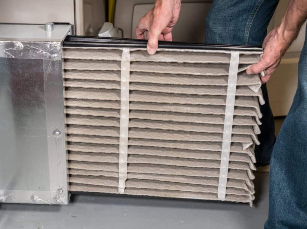
One of the most common issues for any furnace-related problem is simply a clogged air filter . If the airflow is restricted, the exchanger might overheat and shut the whole system down.
Read: Why Does My Furnace Filter Get Dirty So Quickly?
Also: Which Side Of The Air Filter Faces Out?
- Inspect the thermostat
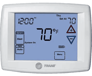
The device has to be set to ‘heat’, it should be properly attached to the wall and you shouldn’t be able to see any loose or frayed wires.
Also, make sure that the time and date are correct and that the batteries have not died.
Have a Question? Ask HVAC Technician
Click here to use the chatbox to speak with one of our technicians. No in-home service calls. No appointments.
Read: Why Does Home Thermostat Say HEAT ON But There Is No Heat?
- Check the electrical components
Inspect the circuit breaker and check the panel for any loose or damaged wires. By the way, the fuse might be tripped or blown, so do check that as well.
2. A Rapidly Blinking Light
The system is operating properly; call for heat.
This means that your unit is on and that it’s giving a call for heat, so everything should be fine.
However, if the furnace is calling for heat all the time, this might indicate that the unit is not responding to the thermostat (follow the instructions mentioned above).
3. Continuous On
There is an issue with the control panel.
If the furnace light stays on, no matter what you do, then there is a problem with the control panel and you will, most likely, have to replace it.
It is quite challenging for a homeowner to figure out by himself, if the control board had actually gone bad or not – to solve such a riddle, you would have to know exactly how the system is attached to works.
Here are the things that can cause your control panel to go bad:
- Loose wiring
After some time, the wires in the system might get loose because of the furnace’s vibration. Moreover, the wires can simply corrode or get damaged over time.
- Clogged filters
Restricted airflow can make the blower motor overheat.
- Dirty or wrong fuse

A fuse might be too small for your system or simply dirty. This, in its turn, will cause the control board to break down.
4. Continuous Off
The power is off.
Here, you would have to check your power source. Hopefully, the issue is with the power and not the actual unit.
To find out whether or not your furnace is getting electricity, throw the thermostat’s fan switch to ‘on’. If the fan starts working, then your unit is receiving electricity.
In case that didn’t help, locate the breaker panel and the circuit that controls the panel. The circuit breaker might have tripped, in such a case, the switch would be either in the ‘off’ or the middle position.
Another thing that you can do is check the furnace switch that is usually located on the unit or on the wall right next to the furnace. The switch should be in the ‘on’ position.
Tip: if you had to change the position of any of the switches, make sure to give the furnace at least a few minutes as some units get switched on with a delay.
Now, we’ll get into the flash patterns of the various Trane furnace error codes.
5. 2 Flashes
There has been a lockout.
If you can, check for miswiring.
Your unit might also have a clogged pilot tube. To clean the components, get a needle and carefully scrape the inside of the tube.
Another possible issue that can cause a system lockout is humidity in the unit.
It is absolutely normal for high-efficiency furnaces to produce condensation during the operation process, but the system should also be able to get rid of the excess moisture.
If the unit fails to successfully do that, the condensate drains might be blocked, or there may be problems with the condensate pump, or there are issues with the condensation line.

6. 3 Flashes
A pressure switch error.
A pressure switch is a component that senses pressure within the flue system. It is a safety mechanism that helps protect the system from overheating.
Here are some steps that you can follow to fix the problem:
- Locate and then remove the front access panel.
- Unplug the 24-volt wires from the switch (if you don’t feel comfortable working with wires, leave this to a professional).
- Connect an ohmmeter to the switch. Check the pressure switch terminals as soon as the fan begins to run. The readings should be close to zero, if they are not, then the actual pressure switch needs to be replaced.
- If the switch is okay, then turn the unit off and let it cool for at least 30 minutes.
- Test the inducer fan – simply try spinning it manually. If the component spins freely, then proceed to the next step.
- Inspect the venting pipes. Leaves, nests, and debris might be clogging them.
- Remove the obstructions and check if the flashes had gone away.
Read: Why Gas Furnace Is Overheating?
7. 4 Flashes
There is an open temperature limit circuit issue (or an open high limit switch).
Make sure that the flame sensor rod on the switch is not dirty.
8. 5 Flashes
The unit sensed a flame when no flame should be present.
Check the flame sensor and the gas valves. The latter might be stuck or leaking gas.
Read: How Long Do Flame Sensors Last?
9. 6 Flashes
A reversed polarity issue or poor grounding.
If you know how to work with wires, you can check the connections. Verify that the polarity at the furnace is correct (the neutral wire should not be connected to where the hot wire should be).

10. 7 Flashes
There is a gas valve circuit error.
You would have to check the gas valves. Ensure that they are not leaking any gas and that the valves are not stuck.
How do you know if your gas valve is leaking?
Tip: always start your inspection from the pipes that go towards the furnace and end with the pilot tube and burners.
You can use a carbon monoxide detector, a special gas detector, or a soap spray (dump the solution on the fittings to ensure that no bubbles get formed).
Read: Why Furnace Is Running But Not Blowing Air?
11. 8 Flashes
There is a low flame.
This might be because of low gas pr e ssure or an issue with the flame sensor. You can try removing the sensor and cleaning the component with very light grit sandpaper.
12. 9 Flashes
Check your ignitor.
Make sure that the furnace is receiving power, inspect the connections and the circuit board.
Usually, the actual furnace has a longer lifespan than the ignitor. So, perhaps, the time has come to change the component.
How to Enter Service Mode on a Trane Furnace ?
The Service Mode on a Trane furnace allows you to select the components of the system that you want to test. The unit will selectively turn the dampers, heaters, compressor, etc. on and off and then perform a service test to find out if everything is okay.
Simply press the key that says ‘Service Mode’ to enter the menu. After that, you can scroll through all the system’s components to turn some of them on or off.
Do bear in mind that the service mode screen will automatically revert back to the general display if no key had been pressed for over 30 minutes.
Read: American Standard Furnace – Troubleshooting Guide
How to Enter the Status Menu on Trane Furnace ?
You can enter the Status Menu to view the unit’s components status, temperature and humidity levels, and different setpoints.
To enter the menu, press the Status key. You can press the ‘+’ to add a certain screen to your custom menu (this will save you quite some time in the future, as you wouldn’t have to go through all of the system’s components, in order to find what you’re looking for).
Just like with the Service Mode, the device will return to its regular display, if no one presses the keys for 30 minutes.
Final Thoughts
Now that we’ve covered the Trane furnace error codes, hopefully the next time your furnace starts blinking at you, you will know just how to approach the issue. But remember that not every time it flashes necessarily mean there’s a problem. Check back with our list any time to be sure.
Related: Goodman , Lennox , Carrier , Rheem , & Bryant Furnace Error Codes
Related Posts
There are quite a few things that can make your unit short cycle. A Lennox…
See Trane Error Code 126? Flashing lights and error codes are the HVAC equipment’s way…
If there is ever a problem with your Rheem water heater, you can consult our…
If your gas furnace makes a clicking sound at the beginning of the heating cycle,…
Cold air coming from the vents during winter is definitely a reason for concern. Your…
- Trane Manuals
- Air Conditioner
- Voyager YH Series
- Installation, operation and maintenance manual
Trane Voyager YH Series Installation, Operation And Maintenance Manual
- page of 64 Go / 64
Table of Contents
Troubleshooting, model number description.
- Model Number Notes
General Information
- Unit Description
- System Input Devices and Functions
- Unit Inspection
- Unit Clearances
Unit Dimensions
Unit weights, installation.
- General Unit Requirements
- Main Unit Power
- Space Temperature Averaging
Factory-Mounted Unit Options
- Circuit Breaker (FIYUCB) and Unit Disconnect (FIYUDC)
- Powered and Unpowered Convenience
- Return Air Smoke Detector
- Through the Base Gas Utility Option
- Air-Fi™ Wireless Communication Interface (WCI)
- Verifying Proper Air Flow (Units with Belt Drive Indoor Fan)
- Economizer Start-Up
- Compressor Start-Up
- Dehumidification Option
- Heating Start-Up
- Variable Air Volume Applications (Multi-Zone, Traditional VAV)
- Final System Set up
Sequence of Operation
- Reliatel Controls
- Two-Speed Indoor Fan (Title 24) Control
- Single Zone Variable Air Volume (Single Zone VAV) Control
- Variable Air Volume Applications (Traditional VAV)
- Constant Volume or Variable Air Volume Applications (SZVAV or Traditional)
Maintenance
- Fan Belt Adjustment-Belt Drive Units
- Monthly Maintenance
- Final Process
- Reliatel Control
- System Status Checkout Procedure
- Resetting Cooling and Heating Lockouts
- Zone Temperature Sensor (ZTS) Service Indicator
- Zone Temperature Sensor (ZTS) Test
- Programmable and Digital Zone Sensor Test
Wiring Diagrams
Advertisement
Quick Links
- 1 Model Number Description
- 2 Model Number Notes
- 3 Unit Description
- 4 Wiring Diagrams
- Download this manual
Related Manuals for Trane Voyager YH Series

Summary of Contents for Trane Voyager YH Series
- Page 1 Installation, Operation, and Maintenance Packaged Rooftop Air Conditioners Voyager™ – Cooling, Gas/Electric 12.5 to 25 Tons, 60/50Hz Model Number: YS*150–300 YH*150-300 SAFETY WARNING Only qualified personnel should install and service the equipment. The installation, starting up, and servicing of heating, ventilating, and air-conditioning equipment can be hazardous and requires specific knowledge and training. Improperly installed, adjusted or altered equipment by an unqualified person could result in death or serious injury.
- Page 2 (Global Harmonized System of Classification and compounds have the same potential impact to the Labeling of Chemicals) guidelines for information on environment. Trane advocates the responsible handling of allowable personal exposure levels, proper all refrigerants-including industry replacements for CFCs respiratory protection and handling instructions.
- Page 3 Copyright This document and the information in it are the property of Trane, and may not be used or reproduced in whole or in part without written permission. Trane reserves the right to revise this publication at any time, and to make changes to its content without obligation to notify any person of such revision or change.
Page 4: Table Of Contents
Page 5: model number description, page 6: model number notes, page 7: general information, page 8: system input devices and functions, page 9: sensors.
- Page 10 General Information The sensor is used to detect high temperatures due to fire Maintenance Instructions provided with the literature in the air conditioning or ventilation ducts. The sensor is package for this unit. designed to mount directly to the sheet metal duct. Each kit In order for the supply air smoke detector or return air contains two sensors.
Page 11: Unit Inspection
Page 12: unit dimensions.
- Page 13 Unit Dimensions Figure 2. Unit dimensional data for 12½ tons standard efficiency units DOWNFLOW CONDENSATE DRAIN CONN 1”(25MM) NPT 7/8”(22MM) DIA. HOLE (UNIT CONTROL WIRE) 1/2 NPT GAS CONNECTION 2”(51MM) DIA. HOLE (UNIT POWER WIRE) SERVICE GAUGE PORT ACCESS Note: ½ NPT Gas Connection Figure 3.
- Page 14 Unit Dimensions Figure 4. Horizontal duct dimensional data 12½ tons standard efficiency units CLEARANCE 48” CLEARANCE 60” 1219 MM 1524 MM FILTER ACCESS DOOR HORIZONTAL UNITS CLEARANCE 72” ONLY 1829 MM SUPPLY RETURN HORIZONTAL CONDENSATE DRAIN CONNECTION 1.0 IN. NPT CLEARANCE 38”...
- Page 15 Unit Dimensions Figure 6. Unit dimensional data 15–25 tons high efficiency units Note: ½ NPT Gas Connection Figure 7. Unit dimensional data 15–25 tons standard efficiency units, 12½–25 tons high efficiency units RT-SVX26R-EN...
- Page 16 Unit Dimensions Figure 8. Horizontal duct dimensional data 15–25 tons standard efficiency units, 12½–25 tons high efficiency units RT-SVX26R-EN...
Page 17: Unit Weights
Page 18: rigging, page 19: installation.
- Page 20 Installation Factory Installed Economizer trap condition which could result in condensate backup due to “air lock”. • Ensure the standard economizer has been pulled out Figure 11. Condensate trap installation into the operating position. Refer to the economizer Installation Instructions for proper setup. Note: Low Leak Economizers do not pull out.
Page 21: Main Unit Power
- Page 22 Installation Controls using 24 Vac Table 4. Zone sensor module wiring Distance from Unit to Before installing any connecting wiring, refer to “Unit Control Recommended Wire Size Dimensions,” p. 12 for the electrical access locations 0–150 feet (0–45.7 m) 22 gauge (0.33 mm provided on the unit and Table 3, p.
- Page 23 Installation Figure 15. ReliaTel relative humidity sensor (dehumidification option) Figure 16. ReliaTel humidistat (dehumidification option) RT-SVX26R-EN...
- Page 24 Installation Figure 17. Typical field wiring diagrams for optional controls (ReliaTel only) BAYSENS075* BAYSENS075* BAYSENS108* BAYSENS106* BAYSENS110* BAYSENS119* BAYSENS073* BAYSENS074* BAYSENS075* ASYSTAT669A OPTIONAL REMOTE SENSOR CONTROL BOX RTRM TEST 1 TEST 2 RT-SVX26R-EN...
Page 25: Space Temperature Averaging
- Page 26 Installation Table 6. Space temperature averaging examples RT-SVX26R-EN...
- Page 27 Installation Figure 19. Typical unit gas train configuration Table 7. Gas heater operating data Heating Input Rate—Btu/h 135,000 205,000 Minimum Supply Gas Pressure Natural/ 3.5” w.c./ 8.0” w.c. Manifold Gas Pressure -0.2” w.c Combustion Blower Suction Pressure (1 -2.1 to -3.1” -0.8 to -1.2”...
- Page 28 Installation Each reading must fall within the utilization range stamped on the unit nameplate. If any of the readings do not fall WARNING within the proper tolerances, notify the power company to Hazardous Voltage! correct this situation before operating the unit. Disconnect all electric power, including remote Excessive three phase voltage imbalance between phases disconnects before servicing.
- Page 29 Installation Modulating Gas Heat 2.5:1 Turndown during compressor starts. Oil foaming occurs when refrigerant condenses in the compressor and mixes with (Optional) the oil. In lower ambient conditions, refrigerant migration The set-up required for equipment ordered with to the compressor could increase. modulating gas heat varies based on the control system When the compressor starts, the sudden reduction in utilized.
Page 30: Factory-Mounted Unit Options
Page 31: powered and unpowered convenience, page 32: return air smoke detector.
- Page 33 Factory-Mounted Unit Options Figure 24. Return air smoke detector for downflow units THREE PIECE HOOD PLASTIC ELBOW METAL INTAKE TUBE SMOKE DETECTOR COPPER TUBE (FACTORY INSTALLED) VINYL TUBES (7-3/4 INCHES LONG) VINYL TUBES (2 INCHES LONG) METAL EXHAUST TUBE (16.34 INCHES LONG) TUBES INSTALL FROM BOTTOM, TOP DOES NOT NEED TO BE REMOVED FROM SMOKE DETECTOR...
- Page 34 Factory-Mounted Unit Options unit must be between 500 and 4000 feet per minute. Most Figure 25. Smoke detector wiring scheme models of equipment covered by this instruction will develop an airflow velocity that falls within these limits over the entire airflow range specified in the evaporator fan performance tables.
Page 35: Through The Base Gas Utility Option
Page 36: air-fi™ wireless communication interface (wci), page 37: pre start, page 38: start up, page 39: dehumidification option.
- Page 40 Start Up pressure of 0.3" w.c. to 2.5" w.c. respectively with a Table 15. Variable air volume mode operation deadband adjustment range from 0.2" w.c. to 1.0" w.c. The System Mode Fan “Auto” Fan “On” setpoint is adjustable on the RTAM Static Pressure DWU or Setpoint potentiometer or through ICS.
Page 41: Final System Set Up
Page 42: sequence of operation.
- Page 43 Sequence of Operation actuator (ECA) to open the economizer damper. The RTRM The potentiometer located on the ECA is non-functional tries to cool the zone utilizing the economizer to slightly when both the temperature and humidity sensors are below the zone temperature setpoint. If the mixed air installed.
Page 44: Two-Speed Indoor Fan (Title 24) Control
- Page 45 Sequence of Operation Demand Controlled Ventilation Operation and remains there for a few minutes, the unit will begin to stage up compressors. If the supply fan is on when the first Demand Controlled Ventilation for units with 2-Speed stage compressor is energized, it will remain energized or Supply Fans will require an additional module (RTVM) for energize at low speed for the duration of Cool 1.
Page 46: Single Zone Variable Air Volume (Single Zone Vav) Control
- Page 47 Sequence of Operation By default, the Design Minimum Position schedule will be point that would make the Design Minimum Position a linear line through all user selectable Design Minimum schedule linear. Position setpoints. The user will have the ability to set the Provisions have been made in Service Test Mode to allow Design Minimum Position at Middle fan speed command for proper damper minimum position setup:...
Page 48: Variable Air Volume Applications (Traditional Vav)
- Page 49 Sequence of Operation If the unit has modulating heat, the unit can be made to do ranges are from 50°F to 90°F. When the zone temperature discharge heating with VAV control. This is done by meets or exceeds the MWU setpoint, the unit will switch to placing a contact closure across the “Changeover Input”...
Page 50: Constant Volume Or Variable Air Volume Applications (Szvav Or Traditional)
- Page 51 Sequence of Operation mounted in the indoor section and is connected to the (a) Exhaust mode 3 is not available with the tracking power exhaust option. RTOM. The clogged filter switch is normally open and will (b) For units configured with the Statitrac option, the Exhaust Damper automatically close when the pressure differential across will open during Ventilation Override modes that request the ex- the filters falls below the clogged filter setpoint.
- Page 52 Sequence of Operation Lead/Lag input. When it is activated, each time the designated lead compressor(s) is shut off due to the load being satisfied, the lead compressor or refrigeration circuit switches. When the RTRM is powered up, i.e. after a power failure, the control will default to the number one compressor.
Page 53: Maintenance
Page 54: monthly maintenance, page 55: final process, page 56: troubleshooting, page 57: resetting cooling and heating lockouts, page 58: zone temperature sensor (zts) service indicator, page 59: programmable and digital zone sensor test.
- Page 60 Troubleshooting WARNING Hazardous Voltage! Disconnect all electric power, including remote disconnects before servicing. Follow proper lockout/ tagout procedures to ensure the power can not be inadvertently energized. Failure to disconnect power before servicing could result in death or serious injury. 1.
Page 61: Wiring Diagrams
Page 62: warranty.
- Page 63 Warranty residential application. Commercial use is any application where the end purchaser uses the product for other than personal, family or household purposes. *A 5 year limited warranty is provided for the optional Low Leak Economizer, when combined with the optional FDD (Fault Detection and Diagnostics) option.
- Page 64 For more information, please visit trane.com or americanstandardair.com. Trane and American Standard have a policy of continuous product and product data improvement and reserve the right to change design and specifications without notice. We are committed to using environmentally conscious print practices.
This manual is also suitable for:
Rename the bookmark, delete bookmark, delete from my manuals, upload manual.
Trane Furnace Red Light Flashing [All Blinks Solved]

Most often, Trane furnace owners experience flashing red light issues on their furnaces. The Trane furnace red light flashing basically corresponds to the specific error codes in the furnace unit.

While operating, the red light may start flashing 1, 2, 3, 4, 5, 6, 7, 9, or constantly. These types of errors primarily indicate that the system has been locked out from its normal operation currently.
But each error code means different things depending on the number and speed of the light blinking. Today, we are going to explore each of the errors with detailed information regarding the reasons and simple solutions. So, let’s get started…
Table of Contents
1. red light flashing 1 time [no call for heat].
- 2. Red Light Flashing 2 Times [External lockout]
3. Red Light Flashing 3 Times [Pressure Switch Error]
- 4. Red Light Flashing 4 Times [Tripped High-Limit Switch]
- 5. Red Light Flashing 5 Times [Flame Detect Fault]
- 6. Red Light Flashing 6 Times [Power Reversed Polarity Or Poor Grounding]
7. Red Light Flashing 7 Times [Gas Valve Circuit Error]
- 8. Red Light Flashing 9 Times [Igniter Issue]
- 9. Trane Furnace Red Light Flashing Constantly
How do I reset my Trane code?
Where is the reset button on a trane xr95 furnace, where is the pilot light on the trane furnace, it’s a wrap.
Go through our comprehensive guide to find the corrective approaches to fix any error codes on the Trane furnace.
The trane furnace’s red light flashing 1 time means that the system is not getting any calls for heat. So, it means that the unit is waiting for the signal from the thermostat.

Sometimes, the light will still flash even setting the temperature. Anyway, note down the possible reasons why the furnace is not responding to the thermostat:
- Clogged air filter
- Wrong installment for the thermostat
- Loose and damaged wiring
- Defective circuit breaker
- Blown fuses
Here are the needed solutions steps that you should follow to fix the issue:
- First of all, check the circuit breaker and the surrounding wirings.
- Tighten the loose wire and replace the defective ones.
- Replace the blown fuse as well.
- Now, inspect the thermostat. Set the mode to ‘heat.’ Replace the damaged batteries and loose wires from the device.
- Also, make sure the correct time and date are on the thermostat. Verify a proper installment of the device on the wall.
- Then, locate the air filter. Clean the clogged debris from the filter to prevent airflow restrictions.
- The red light flashing issue should be resolved.
2. Red Light Flashing 2 Times [External lockout]
Trane Furnace’s red light blinking 2 times tells you there is an external lockout on the furnace.
This is one of the most common error codes that Trane furnace users face. When there have glitches in the power supply, the furnace catches this error.
- First, turn off your furnace, And turn off the pilot light as well.
- Now locate the reset button of the furnace. Basically, you will find the reset button inside the blower housing. After accessing the reset button, press it.
- Keep holding the button for about 30 seconds. Make sure you are not pressing the button so hard.
- You will hear a beep sound from the unit. If yes, release the button and wait until the noise has gone out. It will do a hard reset on the furnace.
- If your furnace has not a reset button, just leave the furnace unplugged for some time. Don’t forget to turn off the furnace breaker.
- Then, turn on the furnace.
For your better understanding, you can read our comprehensive guide on how to fix Trane Furnace blinking 2 times .
Trane Furnace’s red light blinking 3 times indicates the draft pressure error. A pressure switch is an essential piece of equipment for the furnace which works through a safety mechanism to protect the system from overheating.
Basically, it senses pressure within the flue system. Malfunctioning from this switch leads to the 3 times errors on the red light.
Here we have explored the step-by-step solutions to check out the faulty pressure and the tips to resolve the issue.
- First, remove the front access panel. Now locate the pressure switch. You will find 24-volt wires connected to the switch. Disconnect the wires very carefully.
- This time, measure the voltage of the switch using an ohm meter. Measure the voltage as soon as the fan begins to run. It should be zero.
- If not, be sure the pressure switch is defective. Replace it. Also, if you get a zero reading, do a power cycle on your furnace by unplugging it for about 30 minutes.
- Meanwhile, check out the inducer fan. Spin it manually. Remove the obstruction from the fans. Then, inspect the venting pipes. Make sure the pipes are completely unclogged.
- Now, check if the flashing has gone away.
4. Red Light Flashing 4 Times [Tripped High-Limit Switch]
It is a common scenario of the Trane furnace that the red light blinks four times and blows cold air only. Flashing 4 times on the red light mainly notifies that the high limit switch has been tripped.

One of the leading causes of tripping a high-limit switch is a clogged air filter. If the air filter is blocked by debris, the flame sensor fails to detect temperature accurately, and the furnace gets overheated.
Blockage in the air filter creates obstruction in airflow, and the furnace stops blowing hot air as a safety mechanism.
Faulty wiring or installation and dirty flame sensor rod are other possible reasons for this. Whatever the reason is, follow our below instructions to fix the Trane furnace 4 times blinking issue.
- First, you have to reset the heater by unplugging it for some time.
- Then, concentrate on the air filter. Clean out the debris from the filter and around the system.
- Unblock the flame sensor rod and furnace blowers to prevent overheating issues from the unit.
- Take a look at the pilot light. Replace the defective pilot light.
- Ensure a stable installation of the furnace.
- If all the above steps fail to resolve the issue, be sure the high-limit switch gets defects. Replace your Trane furnace high-limit switch as soon as you can.
5. Red Light Flashing 5 Times [Flame Detect Fault]
Most of the time, the Trane furnace catches the error code of 5. When the red light starts blinking five times, it tells that the unit sensed a flame in such a period when no flame should be present.
So, the problem is related to the flame sensor. A faulty flame sensor never detects the heat that has been turned on. Either the sensor is cracked, broken, or cracked.
This may happen after long wear and tear. Also, the problem may start from a gas valve that has closed slowly or the burner flame lingering. It may be stuck by debris or leaking gas.
- Turn off the furnace first.
- Then turn off the gas valves.
- Now, unscrew the mounting screw.
- Clean the valves properly and ensure they are completely blockage free.
- Repair for leaking gas on the unit.
- Now, remove the flame sensor carefully.
- Verify if the sensor is dirty or burnt out. Clean it properly.
- If the sensor is broken or cracked, replace the defective sensor.
6. Red Light Flashing 6 Times [Power Reversed Polarity Or Poor Grounding]
Six times red light blinking on the Trane furnace mainly signals a reversed polarity issue or poor unit grounding. That means the AC power has reversed or the supplied voltage is too low.
Here the furnace control board is sensing the reversed polarity. In short, the heater is facing a glitch power supply. Also, if the furnace is not installed on stable ground or placement, the unit will catch the same error code.
- First of all, check out all the wiring connectors of the furnace. Replace the damaged and cracked wiring.
- You have to ensure that the black hot wire has about 120 V to ground. Also, the white neutral wire has to be zero volts.
- The neutral wire should not be connected to the place where the hot wire is connected. It will ensure the correct polarity of the furnace. Now, disconnect the electrical plug from the wall outlet.
- Leave the furnace unplugged for some time and do a power cycle through the unit. It will assist in eliminating the power glitches like power spike, which is the culprit of giving the code on the board.
- Finally, you have to ensure the igniter’s proper grounding. It should not be grounded through any cracked place in the ceramic base.
- Verify the stable installment of the furnace as well. After resolving the igniter and wiring issue and still, you are getting the same code, replace your furnace control board .
If the Trane furnace red light is blinking 7 times error codes, be sure there has a circuit error on the gas valve.
That means either the gas valve is stuck by debris or blocked. Sometimes, leaking gas from the valve leads to the same error code. The other possible reasons are:
- Faulty hot surface igniter
- Malfunctioning of the burner system
- Faulty flame sensor,
- Defective control board
- First of all, power off the furnace at the breaker. Check the circuit breaker and the wiring. Replace the blown fuses.
- To troubleshoot the issue, you have to locate and check out the gas valve. Clean out the valves and make them clogged-free.
- Now check for gas leaking from the valve. You can use a carbon monoxide detector for this. Also, you may use soapy spray on the fitting to verify the bubbles. Repair the gas leakage.
- Clean out the complete burner system across from the flame rod. If needed, replace the defective control board.
8. Red Light Flashing 9 Times [Igniter Issue]
The Trane furnace’s red light blinking 9 times specifically determines the igniter issue of the unit. The problem started with the Hot Surface Igniters.

Also, if the furnace is not receiving power properly or for a lower voltage supply, the red light will flash.
Improper grounding of the igniter and malfunctioning of the thermostat can cause this as well. However, here is the included solution procedure to fix the issue efficiently:
- Turn off your furnace before starting.
- Now check the igniter.
- Check for any visible damage signs on the igniter. Replace the faulty hot surface igniter.
- If the igniter replacement can’t solve the issue, ensure that the furnace is receiving power.
- Inspect all the wiring connections. Replace the damaged ones.
- Check out the thermostat as well. Replace the defective thermostat.
You can also watch the tutorial to replace the hot surface igniter.
9. Trane Furnace Red Light Flashing Constantly
If your furnace’s red light is flashing continuously, there is no problem with your unit. All the operation is quite normal, and you needn’t be concerned about continuous flashing.
If the red light blinks in numbers, be sure the furnace has a problem. It indicates that the system is locked out of its normal function.
To reset the error code from the Trane furnace, you just need to reset the circuit breaker. Just disconnect the furnace from the breaker and leave it unplugged for some time to reset the code.
All Trane furnaces model has figured a reset button. You will find the red-figured reset button near the burner of the furnace. You can reset the unit by pressing the button.
You can locate the pilot light on the bottom of your furnace. The pilot light is controlled by a control knob.
Well!! After reading the complete article, now you have a crystal clear about each of the error codes on the Trane furnace. You can easily troubleshoot the flashes by following the above solution procedures effectively.
But still, if you have any further queries regarding Trane Furnace’s red light flashing issues or other, don’t be late to ask us through comments. We will reply to you ASAP with possible solutions.

About William
William is the founder of Fireplacehubs.com. He has real life practical skills in fixing smoker & heating appliance issues. He loves to share his knowledge & helps others in fixing their appliances & saving their money. William firmly believes that anyone can repair his or her unit with the correct guidance & knowledge. See more at about us .
4 thoughts on “Trane Furnace Red Light Flashing [All Blinks Solved]”
Just making sure since the red light is blinking constantly with no brakes in between that nothing is wrong and I should not be concerned, right? I appreciate your help.
Yes, if your furnace’s red light is flashing continuously, there is no problem with your unit. All the operation is quite normal, and you needn’t be concerned about continuous flashing.
Wish you all the best!
My Trane XR90 is blinking continuously but the unit will not start. I think it is slow blinking, meaning it is not getting a signal to heat from the thermostat. What should I check? What wires from the thermostat tell the furnace to turn on?
Generally, a furnace doesn’t respond to the thermostat due to a clogged air filter, the wrong installment for the thermostat, loose and damaged wiring, a defective circuit breaker, or blown fuses.
Well, to fix the issue, do the followings-
1. First of all, check the circuit breaker and the surrounding wirings. 2. Tighten the loose wire and replace the defective ones. 3. Replace the blown fuse as well. 4. Now, inspect the thermostat. Set the mode to ‘heat.’ Replace the damaged batteries and loose wires from the device. 5. Also, make sure the correct time and date are on the thermostat. Verify a proper installment of the device on the wall. 6. Then, locate the air filter. Clean the clogged debris from the filter to prevent airflow restrictions.
Hopefully, your problem will be solved.
Best of luck!
Leave a Comment Cancel reply
Save my name, email, and website in this browser for the next time I comment.
Trane Defrost Control Board Led Codes: Decoding The Secrets For Optimal Performance
Trane defrost control board LED codes are important for diagnosing and resolving issues within Trane heating and cooling systems. These codes provide vital clues to technicians, allowing them to pinpoint problems and optimize performance. By understanding and decoding these LED codes, you can achieve optimal performance and efficiency for your Trane unit.
Imagine the inner workings of a heating and cooling system as a complex labyrinth, each component intricately linked to the other. Now picture a small LED light on a control board, silently beaming out crucial information that holds the key to diagnosing and resolving issues within the system.
These codes are the language that only a select few can decipher: HVAC technicians and professionals specializing in Trane units. Armed with advanced knowledge and expertise, these individuals are like detectives, unraveling the mysteries behind the Trane defrost control board LED codes.
But why are these codes so important? Well, they provide vital clues that allow these technicians to pinpoint problems, optimize performance, and ultimately ensure the smooth operation of Trane heating and cooling systems. In this article, we will explore the secrets behind decoding these LED codes, equipping you with the tools to achieve optimal performance and efficiency for your Trane units. Welcome to the world of Trane defrost control board LED codes, where a single blinking light can reveal a universe of possibilities.
Table of Contents
I. Overview of Trane Defrost Control Board LED Codes
A. introduction to trane defrost control board.
The Trane defrost control board is a vital component in Trane heating and cooling systems. It is responsible for regulating the defrost cycle, ensuring optimal performance and energy efficiency. The control board uses LED codes to communicate diagnostic information to technicians, enabling them to identify and resolve issues.
B. Importance of LED codes in diagnosing issues
The LED codes on the Trane defrost control board are crucial in diagnosing issues within the system. By interpreting these codes, technicians can quickly identify the specific problem, saving time and effort. This allows for efficient troubleshooting, resulting in faster resolution and minimized downtime.
C. Brief explanation of LED code structure
The LED codes on the Trane defrost control board follow a specific structure. Each code corresponds to a different issue or condition within the system. Understanding this structure is key to decoding the LED codes and effectively troubleshooting the system.
D. Common Trane models that use LED codes
Trane defrost control boards with LED codes are used in various models of Trane heating and cooling systems. Some common models include the Trane XV20i, XV18, and XL20i. These models utilize the LED codes to provide valuable diagnostic information for technicians.
II. Understanding Trane Defrost Control Board LED Codes
A. led code meanings and their corresponding issues.
- Code 1: Normal operation
- Code 2: Low-pressure switch open
- Code 3: High-pressure switch open
- Code 4: Evaporator coil sensor fault
- Code 5: Ambient temperature sensor fault
- Code 6: Outdoor temperature sensor fault
- Code 7: Reversing valve fault
- Code 8: Defrost termination fault
- Code 9: Low-ambient kit fault
Each LED code on the Trane defrost control board signifies a specific issue or condition within the system. It is essential to understand the meaning behind each code to effectively troubleshoot and resolve problems.
III. Troubleshooting Trane Defrost Control Board LED Codes
A. step-by-step troubleshooting process.
- Checking the LED codes: The first step in troubleshooting Trane defrost control board LED codes is to observe and note down the displayed codes.
- Identifying the specific issue based on the code: Once the LED codes are known, the technician can refer to the code meanings and identify the specific issue or condition.
- Inspecting the corresponding components: After identifying the issue, the technician can inspect the corresponding components, such as sensors, switches, or valves, to determine the root cause.
- Diagnosing and correcting the problem: Once the problem is identified and the faulty component is located, the technician can proceed with the necessary repairs or replacements to resolve the issue.
B. Tips for accurate troubleshooting
- Checking for loose connections: Loose connections can cause issues in the system. It’s crucial to check and secure all electrical connections.
- Verifying proper sensor placement: Incorrect sensor placement can lead to inaccurate readings. Ensuring sensors are correctly positioned is essential for accurate diagnosis.
- Assessing the voltage and continuity of components: It is important to measure the voltage and check for continuity across components to ensure they are functioning properly.
- Consulting Trane manuals and technical support: Trane provides comprehensive manuals and technical support resources that can assist technicians in troubleshooting complex issues.
IV. Resetting Trane Defrost Control Board LED Codes
A. resetting the control board to clear led codes.
To clear the LED codes on the Trane defrost control board, it is necessary to perform a reset. This allows the control board to start afresh and eliminates any previously stored error codes.
B. Steps to perform a manual reset
- Turn off the power to the heating and cooling system.
- Locate the control board and identify the reset button or switch.
- Press and hold the reset button or switch for a few seconds.
- Release the reset button or switch.
- Turn the power back on to the system.
C. Automatic reset functionality and its limitations
Some Trane defrost control boards have an automatic reset functionality. This means that the control board will automatically clear the LED codes after a certain period of time or after the issue has been resolved. However, it’s important to note that automatic reset functionality may have limitations, and performing a manual reset may still be necessary in some cases.
V. Advanced Troubleshooting Techniques for Trane Defrost Control Board LED Codes
A. utilizing diagnostic tools for in-depth analysis.
- Multimeter for measuring voltage and resistance: A multimeter is a valuable tool for measuring voltage and resistance in various components of the heating and cooling system. This can help identify issues that may not be apparent through LED codes alone.
- Temperature probes for accurate sensor readings: Temperature probes provide precise temperature readings, allowing technicians to verify the accuracy of sensors and identify any discrepancies.
- Data loggers for monitoring system performance over time: Data loggers can record and analyze system performance over an extended period, helping technicians identify patterns and recurring issues.
B. Interpreting complex or intermittent LED codes
In some cases, LED codes may be complex or intermittent, making troubleshooting more challenging. To interpret such codes effectively, technicians can:
- Identifying patterns or combinations of LED codes: Look for patterns or combinations of LED codes that may provide additional insights into the issue.
- Analyzing historical data to pinpoint recurring issues: If the system has a history of recurring issues, analyzing historical data can help identify underlying causes and implement more effective solutions.
C. Common challenges in troubleshooting and their solutions
- Interference from external factors such as electrical noise: Interference from external factors can disrupt the operation of the control board and affect the accuracy of LED codes. Shielding sensitive components and minimizing electrical noise sources can help overcome this challenge.
- Ensuring correct sensor calibration and accuracy: Incorrectly calibrated or inaccurate sensors can lead to misleading LED codes. Regular calibration and verification of sensor accuracy are essential to troubleshoot effectively.
VI. Preventive Maintenance for Trane Defrost Control Board
A. importance of regular maintenance.
Regular maintenance is crucial for ensuring the optimal performance and longevity of Trane heating and cooling systems. It helps prevent potential issues, improves energy efficiency, and extends the lifespan of the equipment.
B. Maintenance tasks to prevent future issues
- Cleaning and inspecting components: Regularly cleaning and inspecting components, such as coils, fans, and filters, can prevent the buildup of dust and debris that can affect system performance.
- Checking and replacing faulty sensors: Faulty sensors can lead to inaccurate readings and trigger erroneous LED codes. Regularly checking and replacing faulty sensors is essential for reliable operation.
- Monitoring refrigerant levels and pressures: Monitoring refrigerant levels and pressures ensures the system operates within optimal parameters, reducing the risk of issues related to low or high refrigerant levels.
- Calibrating the defrost control board: Periodic calibration of the defrost control board ensures accurate readings and efficient operation.
C. Recommended maintenance schedule for Trane systems
It is recommended to schedule maintenance for Trane systems at least twice a year – once in the spring for cooling and once in the fall for heating. This regular maintenance schedule helps identify potential issues before they escalate and ensures the system is ready for seasonal changes.
VII. Conclusion
In conclusion, understanding and decoding Trane defrost control board LED codes are essential for effective troubleshooting and optimal performance of Trane heating and cooling systems. By familiarizing yourself with the LED code structure, following a systematic troubleshooting process, utilizing diagnostic tools, and implementing regular maintenance, you can ensure the smooth operation of your Trane system and avoid costly downtime. The secrets behind these LED codes are now within your grasp, empowering you to unlock the full potential of your Trane heating and cooling system.
Troubleshooting all HVAC CIRCUIT BOARDS! Methodology and Procedures Used in the Field!
Frequently asked questions (faq), what are trane defrost control board led codes, how can i interpret trane defrost control board led codes, what are some common trane defrost control board led codes and their meanings, can i reset the trane defrost control board, what should i do if i encounter a trane defrost control board led code, final summary: trane defrost control board led codes: troubleshooting and maintenance guide.
In conclusion, this article has provided a comprehensive overview of Trane defrost control board LED codes. The importance of LED codes in diagnosing issues within Trane heating and cooling systems was highlighted, along with a brief explanation of the LED code structure.
Common Trane models that use LED codes were also mentioned. The article then delved into the meanings of each LED code and their corresponding issues, offering a step-by-step troubleshooting process.
Tips for accurate troubleshooting were provided, including checking for loose connections, verifying proper sensor placement, assessing voltage and continuity, and consulting Trane manuals and technical support. The topic of resetting Trane defrost control board LED codes was discussed, with steps for performing a manual reset and an explanation of automatic reset functionality. Advanced troubleshooting techniques, such as using diagnostic tools and interpreting complex or intermittent LED codes, were also explored.
Common challenges in troubleshooting, such as interference from external factors and sensor calibration, were addressed. Additionally, the article emphasized the importance of preventive maintenance for Trane defrost control boards. The recommended maintenance tasks, including cleaning and inspecting components, checking and replacing faulty sensors, monitoring refrigerant levels and pressures, and calibrating the control board, were highlighted.

Hello, I'm John C. Madison, your HVAC guru at Smart AC Fix. With over 20 years of experience as a certified HVAC technician, I've spent years diving into the intricate world of heating, ventilation, and air conditioning systems. My passion for understanding how things work drove me to master the art of AC maintenance and repair. I'm here to share practical, hands-on solutions to your AC problems and help you keep your cooling system running smoothly. From troubleshooting to maintenance tips, count on me for expert advice. When I'm not tinkering with AC units, you'll find me enjoying the great outdoors and staying cool, just like I want for you!
Similar Posts

Safe T Switch Ac: Troubleshooting Guide For Water Filling Issues
The Safe T Switch AC may fill with water due to various reasons. To address this issue and prevent further damage,…

Why Does My Ac Say Wait? Expert Tips To Diagnose And Fix The Issue
Your AC may display the message “wait” due to several reasons, including: 1. Compressor Protection Delay: After a power outage or…

How To Recharge Home Ac System: Step-By-Step Guide For Optimal Cooling
To recharge your home AC system and optimize its cooling capacity, follow these steps: 1. Turn off the AC unit: Make…

2014 Jeep Grand Cherokee Ac Not Blowing? Here’S What You Need To Know
There could be various reasons why the AC in a 2014 Jeep Grand Cherokee is not blowing air. Some common causes…

Why Does My Ac Sound Like Water? Discover The Possible Causes
Your air conditioning unit may sound like water due to the following reasons: 1. Condensation: As your AC cools the air,…

Arctic King Ac P1 Code: Troubleshooting Tips For Error Code P1
The P1 error code on an Arctic King AC indicates a compressor protection mode. This code typically appears when there is…
Leave a Reply Cancel reply
Your email address will not be published. Required fields are marked *
Save my name, email, and website in this browser for the next time I comment.
- Mark Forums Read
- Who's Online
- Thanks / Like Statistics
- Hottest Threads / Posts
- Contracting Business
- Advanced Search

- The ARPA Zone/Open Membership Discussion Forums
- Tech to Tech Chat - Commercial
Trane Voyager compressor 1 lockout
- Cookie Consent We use cookies to improve your website experience. To learn about our use of cookies and how you can manage your cookie settings, please see our Cookie Policy . By continuing to use the website, you consent to our use of cookies.
- Gain access to our free AOP (Ask a Professional) Section to get real answers for your questions. All this and much more is available to you absolutely free when you register ; for an account, so join our community today today! We suggest not registering using an AT&T, BellSouth, AOL or Yahoo email address. If you have any problems with the registration process or your account login, please contact support .

- Jump to page:
Thread: Trane Voyager compressor 1 lockout
Thread tools.
- Show Printable Version
- View Profile
- View Forum Posts
- View Forum Threads

Hi Guys, I got called out to a Trane voyager the other day that keeps showing a fault of 'compressor 1 locked out' The RTRM board shows the cooling failure indicated by 2 1/4 second flashes. I've checked the safeties including LP but can't seem to find anything that would hold it off. The compressor has been checked and when the contactor is jumped, the compressor runs fine with normal pressures and good cooling. I've tried swapping the RTRM board but can't get the compressor to run without jumping it. Even in test mode it goes from the economiser and misses the cooling stage (only 1 compressor fitted) then straight to fan/heat mode. Does anyone have any suggestions?
Is that the one with the terminal strip on the right, and the two test terminals on top? If so, you've probably got two brass jumpers on the terminal board. Then below that is (I think) terminals 13, 14, and 15. Typically, all of those will be jumped out as well. Sometimes external controls will be put there, like a stat with the bulb embedded in the evap for icing control. I think 14 is the common, jumped out to give power 13 and 15. I've seen those connections go bad, usually due to the elements like lots of fog or close to the ocean air. Make sure those connections on the terminal board are tight. The other most common problem I've seen is a switch in the economizer fails. Not allowing stage one to come on (since the econo acts as the first stage of cooling). You'll have to use the schematic to find then jump that switch to see it that is the problem.
Originally Posted by BBeerme Is that the one with the terminal strip on the right, and the two test terminals on top? If so, you've probably got two brass jumpers on the terminal board. Then below that is (I think) terminals 13, 14, and 15. Typically, all of those will be jumped out as well. Sometimes external controls will be put there, like a stat with the bulb embedded in the evap for icing control. I think 14 is the common, jumped out to give power 13 and 15. I've seen those connections go bad, usually due to the elements like lots of fog or close to the ocean air. Make sure those connections on the terminal board are tight. The other most common problem I've seen is a switch in the economizer fails. Not allowing stage one to come on (since the econo acts as the first stage of cooling). You'll have to use the schematic to find then jump that switch to see it that is the problem. I think Stewie has the answer. If you look on the wiring diagram, there are several safety connections that rely on the brass strips of TB1. I have found several units over the years with "undiagnosable" problems that I found in moments, just by checking all the screw heads for tightness. Let us know what you find in this case.
[Avatar photo from a Florida training accident. Everyone walked away.] 2 Tim 3:16-17 RSES CMS, HVAC Electrical Specialist Member, IAEI AOP Forum Rules: Rules For Equipment Owners. Equipment Owners Find a Contractor HERE! Rules For Professional Members * To get your (*), Click Here. How to become a Professional Member.
The unit is the one with a terminal strip with 8 brass connections at the right hand side with Test 1 and Test 2 at the top and E-stop at the bottom right. The numbers 13,14 & 15 that you're talking about being corroded, are these on the RTRM board J1? When I jumped across the test terminals, I saw the economiser damper moving so assumed the economiser was working. If it is the economiser that's holding the first stage off, can I not disconnect the economiser harness to bypass it?
You can turn off the power, disconnect the economizer plug, and then power up the unit. It will see that it is not equipped with an economizer, and the unit will not consider the economizer as a cooling source. If this fixes the issue, consider additional testing of the economizer sensors. The logic module may be getting incorrect information.
Does he have to use the bypass plug like Carrier ?
Originally Posted by timebuilder I think Stewie has the answer. If you look on the wiring diagram, there are several safety connections that rely on the brass strips of TB1. I have found several units over the years with "undiagnosable" problems that I found in moments, just by checking all the screw heads for tightness. Let us know what you find in this case. You know, I was thinking about it, and neither of the problems I mentioned would make the light flash. I think some of those problems have to occur three times to make the light flash; maybe that is for the press switches. Anyway, the manual would probably help narrow down that problem. Should be easy to get online.
The manual states that the blinking lights mean the following; Supply fan fail Programmable ZSM communication failure Manual compressor lockout (one or both circuits) Outdoor coil temp sensor failure (heat pumps only) Gas heat failure Discharge air temperature failure on modulating heat unit Froststat active Outdoor air temperature sensor failure Smoke detector active RTOM Comm. failure Manual compressor lockout is on that list but I don't know what causes this fault because the compressor doesn't even get the signal to run and the fault doesn't reuse even after powering the unit off.
I re-read your posts. You mentioned RTRM board. Is that one of those 'smaller' reliatel boards? The ones that you can hook up either the Trane stat or a conventional stat? Probably the first thing I would do is power down the unit, disconnect all stat wires, then power it up. See if the fault is still there. That will eliminate a couple of things. Looks like all the sensors use the same numbers. Copy then paste this into a search engine: CNT-SVX15D-E4_1111.pdf Look at page 40 for the resistance chart. By disconnecting the stat wires and seeing what happens on power up, then checking the sensors, you will eliminate most of what can go wrong. You said you swapped the boards (hopefully with new), so we'll assume that is not the problem; but don't rule that out completely. I actually like those boards. I always carry the Trane OEM stat on my truck. So if I hook up the Trane stat and it works, but it won't work when jumping out the terminal strip for the conventional stat (or vice versa), then I know I have a problem with the board. Check out the lead lag on page six as well. By cutting or re-connecting that wire, it could tell you something. There's a lot of gems in that manual. Just gotta spend some time looking through it.
We have quite a few of those units and I never look at the board lights. I put my meter on volts DC. And go between terminals 6 and 8. If it's ranging between 30 volts and 0. That will show u there is a cool failure. Also another easy test is to out through test sequence if it skips the test it means it'd in lockout. So joke u said it skipped compressor it means it's in lock out. I learned from a factory class on those units. Normally high pressure, low pressure, discharge line tstats, freeze stats, and defective contactor coil would cause a cool faikure. Also on bigger units the compressors have a internal thermal overload that is wired into this circuit. From there it's elimination of those devices u don't have on u r unit. Sent from my SM-G900V using Tapatalk
The RTRM board I mention is the board on page 6 of that manual. The only stat I think I have connected to that board is on J1 terminals 1-2. This particular site has about 20 of these voyagers on the roof that all seemed to be controlled from a main Trane controller inside the building. You mention carrying an OEM Trane stat to connect to the hoard but which stat would that be and would it be connected to J1 1-2?
Originally Posted by aastyler We have quite a few of those units and I never look at the board lights. I put my meter on volts DC. And go between terminals 6 and 8. If it's ranging between 30 volts and 0. That will show u there is a cool failure. Also another easy test is to out through test sequence if it skips the test it means it'd in lockout. So joke u said it skipped compressor it means it's in lock out. I learned from a factory class on those units. Normally high pressure, low pressure, discharge line tstats, freeze stats, and defective contactor coil would cause a cool faikure. Also on bigger units the compressors have a internal thermal overload that is wired into this circuit. From there it's elimination of those devices u don't have on u r unit. Sent from my SM-G900V using Tapatalk Hi, I measure a pulsing voltage between 6 & 8 so it is showing a cooling failure. The LP and HP both check out to be ok and I'm pretty sure this model doesn't have discharge line T stats but I could be wrong. The unit is only a small one and the compressor doesn't have a thermal klixon. Definatly a few more things to check though so thanks
Originally Posted by marc5180 The RTRM board I mention is the board on page 6 of that manual. The only stat I think I have connected to that board is on J1 terminals 1-2. This particular site has about 20 of these voyagers on the roof that all seemed to be controlled from a main Trane controller inside the building. You mention carrying an OEM Trane stat to connect to the hoard but which stat would that be and would it be connected to J1 1-2? Doesn't sound correct. The J1 is a factory wiring harness. And 1&2 are common and 24vac. The OEM thermostat goes on J6, 1-5 or 1-10 depending on which one you have. A conventional stat goes on J7. But you do not use both. I carry the Service First SEN 1513 thermostat that connects on terminals 1-5 of J6. And the remote sensor SEN 1448 that connects parallel on terminals 1&2 of that same terminal board. Most companies that we're doing work for now do not want the end users playing with the thermostats. So we put the stat in the control panel and drop the remote sensor down the return plenum. Real easy, fast and simple. Saves the customer lots of money, both is service time (no running up and down ladders or messing with ceiling tiles) and energy costs are more controlled. Not to mention no ice ups of the evaps. If you do choose to use the remote sensor, be sure to cut the sensor out on the stat you put inside the unit. So, figure out what type of stat is being used (where it is connected), then get back to me. Glad to help whenever I can. Remember, you can just disconnect all stat wires from J6 and J7 and jump it out like a regular unit from the conventional stat interface at J7, just jump R to G, then R to Y1 and Y2. I think there is still a small time delay, so give it a bit to start up. If that works, then it's probably something external to the unit that is causing problems.
If you only have a sensor hooked to J6 terminals 1&2, then the unit is in a default mode. It thinks the thermostat is broken and will try to maintain something like 75 or 76*F in cooling. It doesn't hurt anything to do this, and I have seen a lot of units wired like that. But typically, a point in time will come when the end user just gets fed up with the warmer temps. So I'll put a stat in the control panel with that remote sensor in the return plenum and set the stat for something like 72 or 73. That gives everyone a benefit. You keep energy costs under control, the end user cannot adjust the stat, yet they get enough cooling to be comfortable.
I haven't read all the posts so forgive me if this has already been added. We've had some bad capacitors on the condenser fan motors. If you have more than 2 motors and the third one comes on with pressure increase, the negative air pressure caused by the two operating motors allows the blades to turn backwards on the third. If the capacitor is bad, it can't overcome this and when it starts, it actually continues to run backwards. This causes a high head pressure lock out. By the time you check it, the pressure switch is made and you're left scratching your head. Just another thing to check. Good luck. "If you can't do it technically, you can't do it tactically."
What is the model number? Tranetek you beat me to it. Sounds like you are having an intermittent failure with a safety control and as stated earlier will lock out after 3 attempts in a cooling cycle. Perhaps a condensing fan motor is overheating and causing this failure. I have seen where a run capacitor is weak and is below the required/recommended micro fared output. This will cause an intermittent failure like you are experiencing. I would check the run capacitor which may be a 25 MFD 440 depending on the model. Depending on the model number there may be a service bulletin on this. Service Bulletin: Condensing Fan Motors RT-SVB 78A-EN
Originally Posted by BBeerme You know, I was thinking about it, and neither of the problems I mentioned would make the light flash. I think some of those problems have to occur three times to make the light flash; maybe that is for the press switches. Anyway, the manual would probably help narrow down that problem. Should be easy to get online. I have not been using the RTRM flashing light very much. Maybe I don't run into a lot of fault conditions that would make it flash. Of course I make it flash when I put it into test mode. Maybe I should print out a page from the Micro book and carry it with me...
Originally Posted by timebuilder I have not been using the RTRM flashing light very much. Maybe I don't run into a lot of fault conditions that would make it flash. That's what got me thinking about it. I think the only time I've seen it flash is when it was so low on charge that it cycled three times in a minute, or whatever the time requirement is. Usually it is a bad board, bad stat, loose connection, or something mis-wired.
BBeerme, I'm not going back to the site until next week but when I do then I'll look at how the unit is controlled and where the stat is wired into. I looked on eBay for them 2 stats/sensors that you mention but couldn't find any, only the SENS074a. I'd like to be able to keep a stat in my van and then when I have a call out to one of these unitson the roof then I can disconnect the sensors/stats connected and adjust the set point on the roof to test, this would work wouldn't it?
The model number is EYSD060BDK. If it's an intermittent fault then I may try to jump the LP switch and then HP switch hopefully this will start the unit, if it does then I know it's one of these that's holding it off. I tried looking for that service bulletin but couldn't find it by typing that into the web, where would I find that bulletin?
- Private Messages
- Subscriptions
- Search Forums
- Forums Home
- The #1 question asked by NEW MEMBERS. Please read this...
- Questions About Becoming A Professional Member? Step Inside...
- SITE Software Issues? Post Them Here
- RULES for AOP - Owner Assistance and Contractors
- AOP Residential HVAC (Beenthere Zone)
- AOP Commercial HVAC
- General Discussion
- Job Wanted/Needed Discussion
- Industry and Forum News
- Webinars and Virtual Events
- Tech to Tech Chat - Residential
- Refrigeration & Ice Making
- Members Inventions **NEW
- Test & Balancing Forum NEW
- Control Sales Forum
- Professional Controls Forum
- Control Jobs Forum
- Chillers Open Forum
- Energy Efficiency and Building Performance Discussion NEW
- Commercial Food Service Equipment
- Residential Geo Thermal / Water Source
- Commercial Geo Thermal / Water Source
- Indoor Air Quality
- Tools & Test Equipment
- Food and Grill Forum
- "Wall of Pride" - Pictures
- "Wall of Shame" - Pictures
- How To Become a Pro and Rules For Pro Members
- Pro's Forum: General Discussion
- Charlie's Corner (Icemeister)
- HVAC Basics **NEW
- Pro Forum: Refrigerants and EPA regulations **NEW
- Pro's Forum: Business & Marketing
- Pro Forum: Residential Refrigeration and Appliances **NEW
- Pro's Forum: Sales
- Pro Forum: Equipment Recalls and Bulletins **NEW
- Pro's Forum: Residential
- Pro's Forum: Commercial
- Pro's Forum: Geo Thermal / Water Source
- Pro's Forum: Refrigeration & Ice
- Pro's Forum: Chillers
- Pro's Forum: Oil Burners
- Pro's Forum: Hydronics/Boilers
- Pro's Forum: Building Science Discussions
- Pro's Forum: Training and Education
- Pro's Forum: Instructors Forum NEW
- Pro's Forum: Tips 'n Tricks of the Trade
- Pro's Forum:The Gun Enthusiast
- Frequently Asked Questions About Submissions
- Manufacturers' Technical Information
- Articles Authored by Others
- Self-Authored Articles
- Submit Quiz Questions
- About the Suggestion Box
- Voice Your Opinions
- Share Ideas
- Report Problems
- Educational, Training & Reference Information
- Manufacturer's Technical Information Links
- Quiz Questions
- Open Forum Discussion
- Split Systems, Package Units, Furnaces
- Geothermal / Water Source Heat Pumps
- Specialty Systems
- Boilers Hydronic, Steam
- Accessories Humidifiers, Air Cleaners, HRUs, Fans, Filters, etc
- Components Coils, Heaters, Motors, etc.
- Compressors
- Oil Burners
- Systems - General
- Accessories Pumps, Cooling Towers, Evap Condensers, etc
- Components Valves, Motors, Condensers, Evaporators, etc
- Refrigeration Systems
- Evaporators, Condensers, Etc.
- Valves, Regulators, Filters, Etc.
- Walk-Ins, Cold Storage
- Food Service Equipment, Display Cases
- Supermarket Cases & Compressor Systems
- Ice Machines
- Controls, Motors, Etc
- HVAC Load Calc Software
- Refrigeration Load Calc Software
- HVACR Software & Online Training
- HVACR Calculators & Apps
- Formulas and Calculations
- In Memoriam
- Licensing, Laws, Codes and Certification
- Jokes, Quotations, Humor, Wisdom Pills
- Practice, Testing Area
- Plumbing Forum Rules
- Plumbing General Open Forum
- Pro's Forum: Plumbing Discussion
- Electrical Forum Rules
- Open Discussion Electrical
- Photovoltaic
- New Products
- Bonding & Grounding
- Motors & Motor Controls
- Test & Measurement
- Tools & Equipment
- Code Violations
- Pro's Forum: Power Quality
- Pro's Forum: Calculations & Electrical Theory
- Pro's Forum: Electrical Business & Marketing
- Pro's Forum: Estimating
- Job Postings
vBulletin Message
The following errors occurred with your submission, quick reply, register now.
Please enter the name by which you would like to log-in and be known on this site.
- Confirm Password:
Please enter a password for your user account. Note that passwords are case-sensitive.
- Email Address:
Please enter a valid email address for yourself.
- HVAC/R Contractor
- HVAC/R Technician/Installer
- HVAC/R Wholesaler/Distributor
- HVAC/R Manufacturer
- Manufacturer Rep
- HVAC/R Consultant
- HVAC/R Engineer
- Facilities manager/Mechanical Engineer
- Homeowner or Building/Equipment Owner (We welcome homeowners and Building owners. Help us customize your experience) Please post in the AOP Section
- Residential HVAC
- Light Commercial HVAC (up to 25 tons)
- Commercial HVAC (over 25 tons)
- Refrigeration
- Hydronic Heating
- Building Automation/Controls
Posting Permissions
- You may post new threads
- You may post replies
- You may not post attachments
- You may not edit your posts
- BB code is On
- Smilies are On
- [IMG] code is On
- [VIDEO] code is On
- HTML code is Off
Forum Rules
- HVAC-Talk.com
© VerticalScope Inc. All Rights Reserved.
COMMENTS
2 flash - system lockout - failure to sense flame. 3 flash - pressure switch failure to close when CBM stops or open when CBM starts (not applicable to 12½ to 25 tons) 4 flash - TCO circuit open. 5 flash - Flame being sensed yet gas valve not energized. 6 flash - Flame Rollout (FR) circuit open (Not applicable to 12½ to 25 tons)
Voyager ™ Commercial ... YC*275B, 305B, 350B, 400B, 500B ©2021 Trane RT-SVX34U-EN Introduction Read this manual thoroughly before operating or servicing this unit. Warnings, Cautions, and Notices Safety advisories appear throughout this manual as required. Your personal safety and the proper ... 4 RT-SVX34U-EN
Steady Red LED - The defrost control board has detected a fault and is in lockout mode. Flashing Red LED - The sensor is not detecting proper temperature, indicating a possible faulty sensor or a wiring issue. Flashing Green LED - The system is in defrost mode, and the board is actively monitoring the process. Steady On - Power is present.
October 04, 2023 13:05. Updated. *LCU ReliaTel RTRM LED2 Diagnostic Testing. On RTRM version 4.0 or higher, the green system LED2 on the RTRM module can provide a quick visual indication of the presence of certain diagnostics. If the green LED2 on the RTRM is blinking with two ¼ second blinks every two seconds, one or more diagnostics are present.
4. Manual compressor lockout (one or both circuits) 5. Outdoor coil temp sensor failure (heat pumps only) 6. Defrost fault condition (heat pumps only) 7. Gas heat failure. 8. Discharge air temperature failure on modulating heat and modulating reheat units. 9. Frostat active. 10. Outdoor air temperature sensor failure. 11. Smoke detector active. 12.
Wiring issue or problem with ignition module or RTRM. 2 Flash. System lockout - failure to sense flame. Failure to ignite, no spark, low/no gas pressure. 4 Flash. TCO (high temperature limit) circuit open. excessive heat in the combustion chamber, low airflow, 5 Flash. Flame being sensed, but gas valve not energized.
What can cause a 2 flash code on the RTRM? Overview: Possible Causes (1-22) 1. Supply fan fail. 2. Zone temperature sensor input failure on CV units. 3. Programmable ZSM communication failure. 4. Manual compressor lockout (one or both circuits) 5. Outdoor coil temp sensor failure (heat pumps only) 6. Defrost fault condition (heat pumps only) 7 ...
• 2 flashes every two seconds indicates a diagnostic is present (V 4.0 or greater) [see p.26 for a list of diagnostics] • Continuous¼ second blink: Test Mode Green Transmit LED • Very fast flash: Normal operation, information being sent to other modules. • Off: System failure Yellow Receive LED • Very fast flash.5 second, off 1.5 second:
Maintenance - Trane Voyager 1 Rooftop Unit TSD User Manual Page 63. Text mode ; Original mode ; Advertising. Maintenance. 63. RT-SVX20A-E4. ... 3 Flashes: Pressure Switch Fail 4 Flashes TC01 or TC02 Open 5 Flashes: Flame w/o Gas Valve 6 Flashes: Flame Rollout Open. Cooling Failure 1. Cooling and heating set point
How do I retrieve fail codes from the RTRM when I have a 2 flash fault code? How do I tell the difference between a RTEM Actuator Fault and a RTEM Communications Failure? List of Light Commercial LED Codes; What are the Economizer fault codes? What are the gas heat fault codes for Reliatel controlled Voyager II units?
1. I figured out the issue. I was focused on air intake and never bothered to check outtake. The lovely lady closed the vents in unused rooms hoping to force more air into the MBR. Opening the registers in all rooms resolved the "open limit device" issue. Glad you figured it out.
Reliatel control boards have "Trane" terminals 1-12 or so as well as "conventional" terminals R-G-Y-W etc directly on the board. Older Voyager units have Voyager or "black book" controls which require a "CTI" or Conventioal Thermostat Interface board to use a regular 24v stat. Post a pic of what you're working on, it would help greatly.
Remove the obstructions and check if the flashes had gone away. Read: Why Gas Furnace Is Overheating? 7. 4 Flashes. There is an open temperature limit circuit issue (or an open high limit switch). Make sure that the flame sensor rod on the switch is not dirty. 8. 5 Flashes. The unit sensed a flame when no flame should be present.
Page 1 Installation, Operation, and Maintenance Packaged Rooftop Air Conditioners Voyager™ - Cooling, Gas/Electric 12.5 to 25 Tons, 60/50Hz Model Number: YS*150-300 YH*150-300 SAFETY WARNING Only qualified personnel should install and service the equipment. The installation, starting up, and servicing of heating, ventilating, and air-conditioning equipment can be hazardous and requires ...
Six times red light blinking on the Trane furnace mainly signals a reversed polarity issue or poor unit grounding. That means the AC power has reversed or the supplied voltage is too low. Here the furnace control board is sensing the reversed polarity. In short, the heater is facing a glitch power supply.
Slow Flash Rate Normal, call for heat (¾ second on, ¼ second off) 1 Flash : Loss of Communication 2 Flashes: System Lockout: Failed to detect or sustain a flame. (failure to ignite, no spark, low/ no gas pressure, etc.) 3 Flashes: Pressure switch problem detected. (no vent air flow, bad CBM, closed at an initial call for heat). Auto reset. 4 ...
Code 7: Reversing valve fault. Code 8: Defrost termination fault. Code 9: Low-ambient kit fault. Each LED code on the Trane defrost control board signifies a specific issue or condition within the system. It is essential to understand the meaning behind each code to effectively troubleshoot and resolve problems. III.
Figure 4 - Variable speed direct drive supply fan An Answer to Market Needs Capacity Modulation † Voyager features dual Scroll compressor units. The dual compressor models are outstanding for humidity control, light load cooling conditions and system back-up applications. Low Ambient Cooling † All Voyager units have cooling capabilities ...
with Voyager 3 Packaged Rooftop Air Conditioners ©2023 Trane BAS-APG048B-EN ... hard hat/bump cap, fall protection, electrical PPE and arc flash clothing). ALWAYS refer to appropriate Safety Data Sheets (SDS) and OSHA guidelines for proper PPE. ... The Trane Symbio™ Service and Installation mobile app is required to setup, edit, and confirm ...
Follow our interactive troubleshooting guide to find answers to your system's problems. Choose from a selection of common HVAC issues or pick your product for help with fixes you can try yourself. Packaged System Troubleshooting. If you are experiencing an issue with your packaged system, our guide can help answer your questions.
Hi Guys, I got called out to a Trane voyager the other day that keeps showing a fault of 'compressor 1 locked out' The RTRM board shows the cooling failure indicated by 2 1/4 second flashes. I've checked the safeties including LP but can't seem to find anything that would hold it off. The compressor has been checked and when the contactor is jumped, the compressor runs fine with normal ...
Voyager® 3 meets your needs for reliability and value while providing updated efficiency ratings and digital advantages. The advanced Voyager 3 redefines proven performance for the future of more sustainable, connected buildings. Deliver new efficiency levels. Trane has raised the bar across Voyager 3's standard and high-efficiency tiers.